
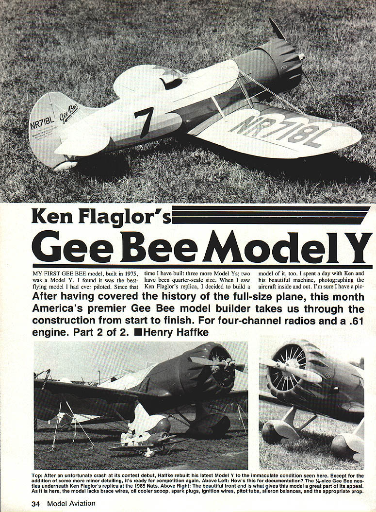
Ken Flaglor's Gee Bee Model Y
My first Gee Bee model, built in 1975, was a Model Y. I found it to be the best-flying model I had ever piloted. Since that time I have built three more Model Ys; two have been quarter-scale size. When I saw Ken Flaglor's replica, I decided to build a model of it as well. I spent a day with Ken photographing his beautiful machine inside and out, which helped in producing accurate scale drawings.
After covering the history of the full-size plane, this article takes you through construction from start to finish for a four-channel radio installation and a .61 engine. Part 2 of 2.
Background and the Nats effort
When the AMA Nats were first held in Springfield, MA, I had flown three Gee Bee models in competition there. Springfield is not only the birthplace of the Gee Bees, but the area is my childhood home as well. With the Nats scheduled there again in 1985, I decided to build two new Gee Bees for competition—both based on Ken Flaglor's Model Y. One would be for Sport Scale, the other fully detailed for FAI Scale.
Using a stack of photos and other research, I produced a good set of scale drawings, cut two sets of parts, assembled two fuselages, and started on the cowls. It took over two months to finish the cowls and dummy engines, and I realized I would not get both models completed in time for the Nats. I concentrated on the Sport Scale model and spent many late nights finishing it.
My good friend Sid Clement agreed to test-fly the model. I had installed an old .60 engine that was very reliable but not very powerful (a non-Schnuerle design). After several attempts to get the model unstuck during testing, Sid tweaked the engine, launched it, and reported, "It doesn't need anything." It flew beautifully but lacked power for more aggressive maneuvers.
Sid suggested a new Webra .61. Although I hated to change engines because the dummy engine had been made to fit the older .60, I bench-run the Webra for a couple of hours and installed it on an Edson adjustable engine mount. To my surprise, the dummy engine fit better over the Webra and the muffler fit with no changes. The subsequent test flight was flawless; the model flew superbly and landed well.
At the Nats the Model Y earned the highest static score of the event, a 97, but my luck in flying ran out. I had been showing Ken around Gee Bee country the night before while the models were static judged. The next morning we assembled the Model Y and took photos with Ken's replica. During the takeoff run the model jumped into the air, settled back down, then lifted off unevenly. A few seconds into the flight a radio failure caused the model to become completely out of control; it rolled onto its back, I fought it upright, then it spun in and hit the ground.
I was disappointed, and repair work was delayed while the radio was being repaired. I rebuilt the front of the fuselage and one wing panel. During that contest season I flew the repaired Model Y in three contests: a poor job in the first two left me second, but by the third contest I was comfortable flying it again and took first by a wide margin. In the short time I've had this model I have enjoyed it immensely and look forward to more flying.
Plans and variants
The plans presented here include details for building all Model Y variants:
- NR11049: the first Model Y; had a ring cowl (see Plate 3). Its landing gear differed and the aft end had a tail skid rather than a faired tail wheel.
- NR718Y (original): had a smooth cowl and open gear fairings; appeared at the Chicago Air Races in 1933 with a bump cowl, long windshield, and fully faired landing gear legs.
- NR718L (Ken Flaglor's replica): is the main subject for the drawings; all details shown are specific to his aircraft.
All stringers and ribs on the drawings are exactly to scale, with markings shown in their exact positions relative to ribs and stringers.
Correct colors:
- NR11049: white with red trim and black pinstripe separating the colors.
- NR718Y (original): cream with red trim and black pinstripe.
- NR718Y (1933): white with red trim and black pinstripe.
- NR718L: cream with red trim and black pinstripe.
Choose your version, cut out the parts, and start construction.
Construction
Fuselage
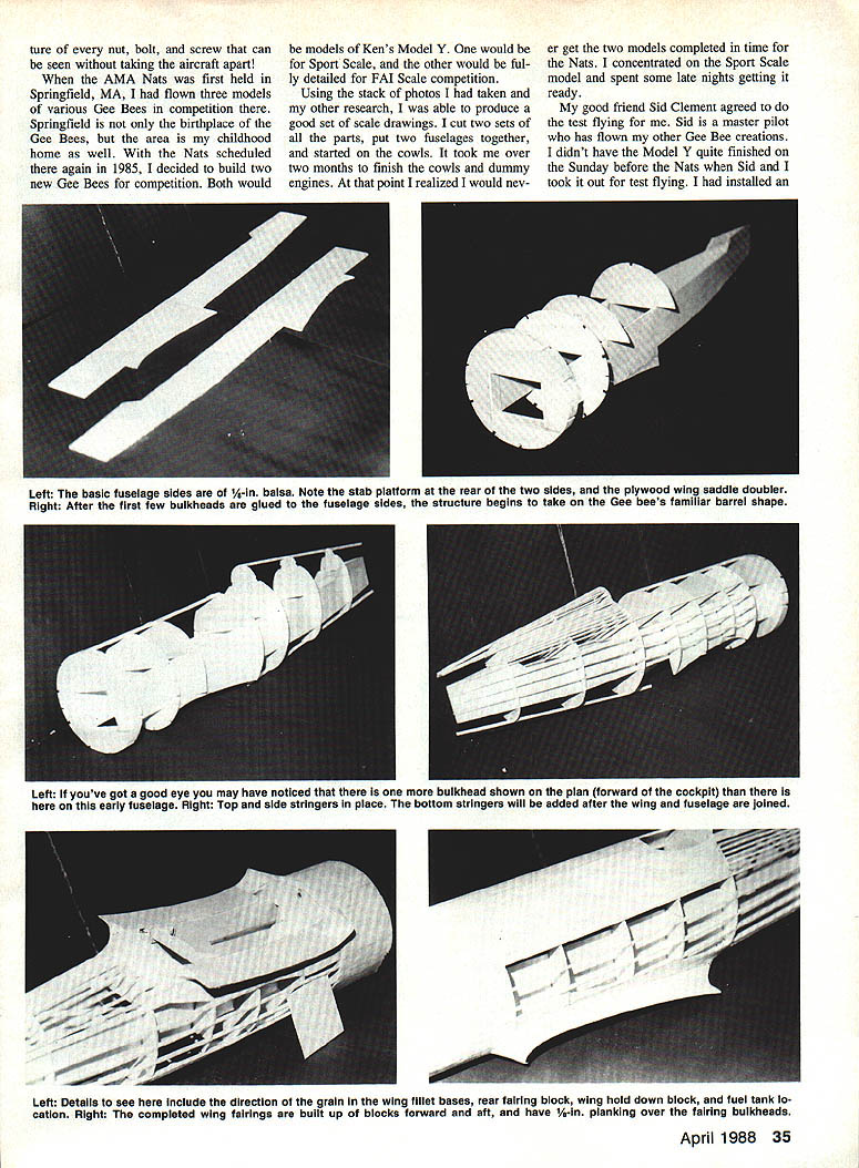
- Prepare the 1/8-in. fuselage sides (marked with small arrows on the drawing). Note the platform for the stabilizer added to the top of the aft end.
- If building NR11049, note the slight difference in the front end of the sides (shown on Plate 3). Forward fuselage bulkheads are different and are shown next to the drawing of the fuselage front end.
- Laminate the plywood fuselage doublers to the basic sides; they extend from F-6 to the front end. Make a right and a left side.
Start the fuselage structure by gluing the 1/8-in. ply F-3 and the 1/8-in. balsa F-2 bulkheads in place. Keep everything square and let this assembly dry completely before proceeding. Add the remaining fuselage bulkheads, bring the tail together and join. Install the top and bottom center stringers, then alternate remaining stringers—gluing one on one side and a matching stringer on the other as you progress.
Prepare the firewall by mounting the engine and making the required holes for fuel and throttle linkage. Locate the firewall against F-2 but do not install it permanently yet. Make a compartment for the fuel tank between F-2 and F-3 and install the tank. The top and front of the fuselage can now be sheeted or planked with 1/8-in. balsa. Planking is preferred, but sheeting works well since there are no compound curves. This completes the basic fuselage structure.
Cowl and dummy engine
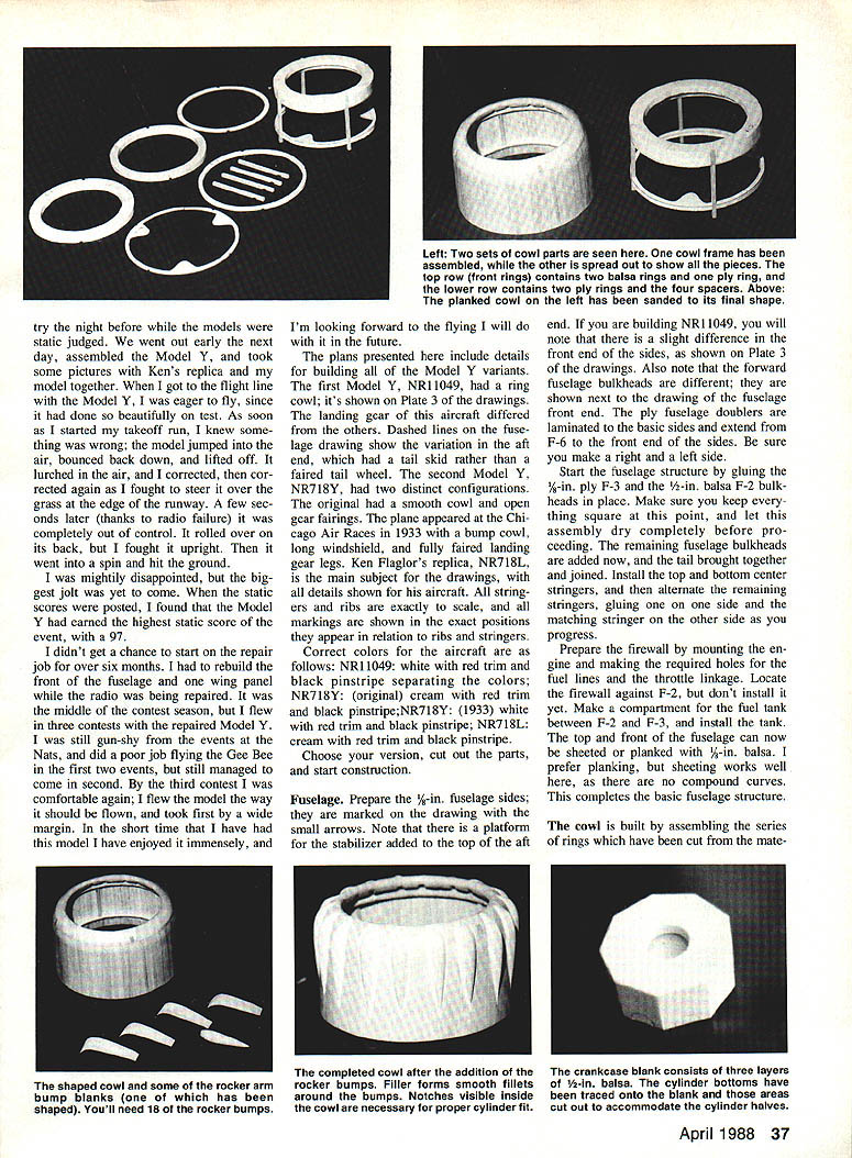
- Build the cowl by assembling the series of rings cut from the material. You can build the entire front end with the engine secured to the firewall and the dummy engine in place.
- Line up the cowl and attach to the firewall with sheet metal screws through the mounting tabs on C-4. After completing this unit, fit the firewall to the front of the fuselage and epoxy it in place against F-2. This method allows fine tuning for a perfect cowl-to-fuselage fit.
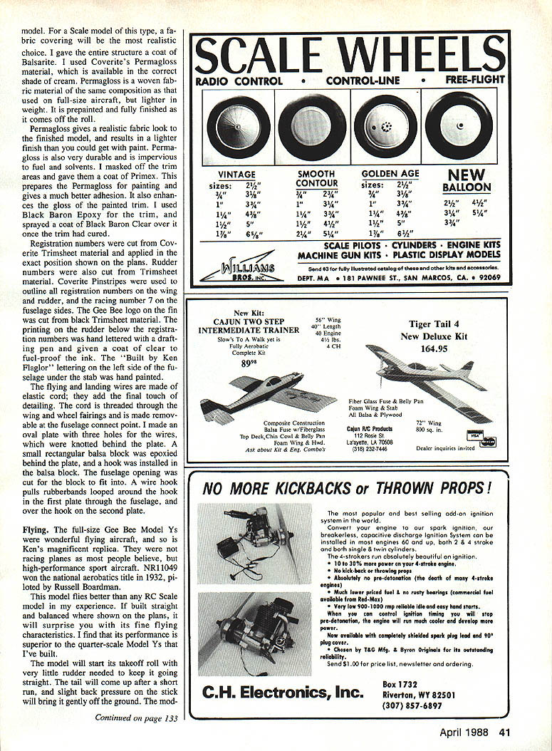
After planking the cowl, carve and sand it to final shape before adding cowl bumps. The bumps go around the front cowl curve and must be carefully fitted. Cut blanks for the bumps on a bandsaw, carve and rough sand the tops, then glue them in place. If the dummy engine is built, glue one bump exactly where it belongs at the top of each side of each cylinder.
When the cowl and bumps are complete, final sanding and finishing can be done. The cowl and dummy engine assembly is time-consuming but is the most impressive part of the model.
Dummy engine details:
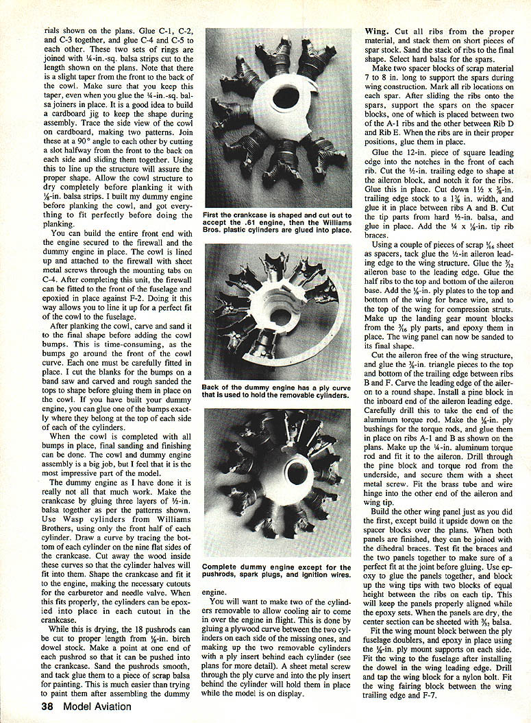
- Make the crankcase by gluing three layers of 1/2-in. balsa together per the patterns.
- Use Wasp cylinders from Williams Brothers, using only the front half of each cylinder.
- Trace the bottom of each cylinder on the nine flat sides of the crankcase, cut away the wood inside the curves so the cylinder halves fit, shape the crankcase, and fit it to the engine with cutouts for carburetor and needle valve.
- Epoxy the cylinders into place when fitted properly.
Make 18 pushrods from 3/32-in. birch dowel stock. Make a pitot at one end of each pushrod so it can be pushed into the crankcase. Sand pushrods smooth and tack glue them to scrap balsa for painting—this is easier than painting them after assembly.
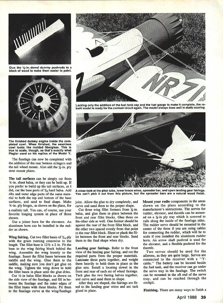
Make two cylinders removable to allow cooling air in flight. Glue a plywood curve between the two cylinders on each side of the missing ones, and make removable cylinders with a ply insert behind each. A sheet metal screw through the ply curve into the ply insert will hold them for display.
Wing
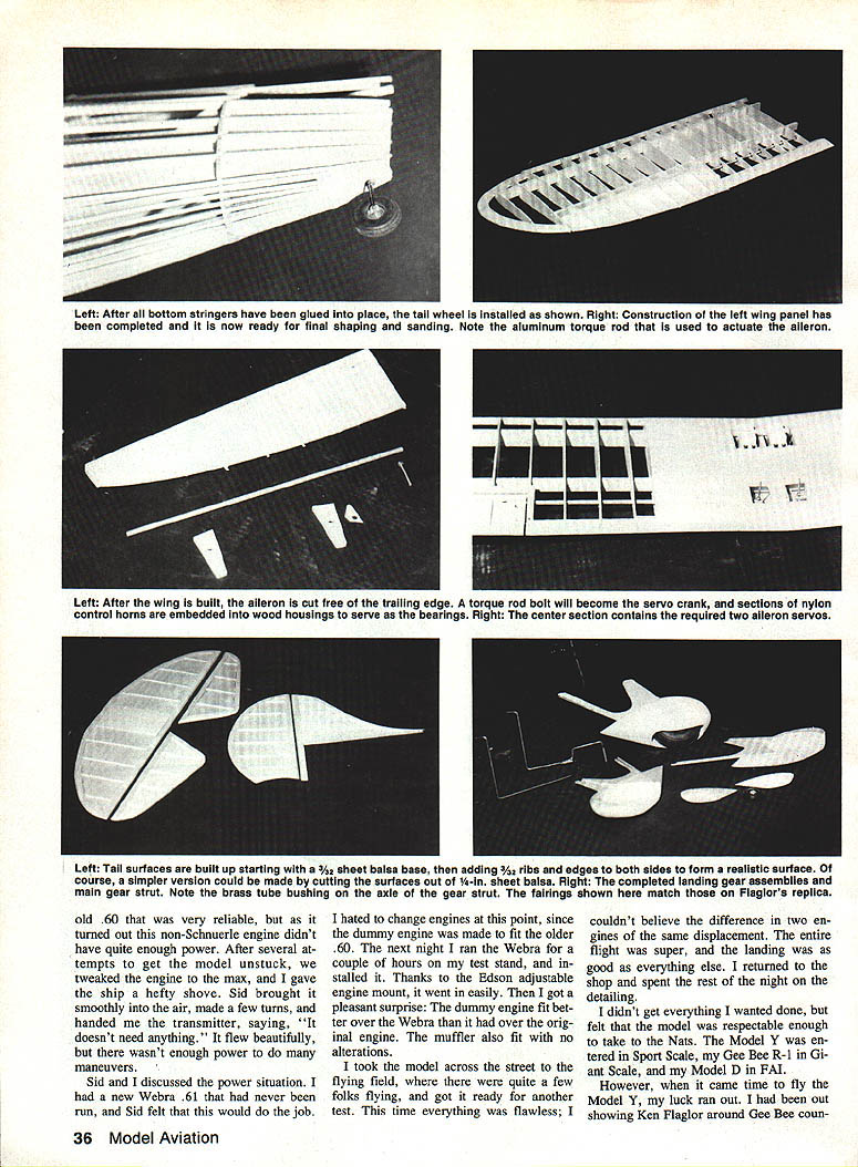
- Cut all ribs from the proper material and stack them on short pieces of spar stock. Sand the stack to final shape. Select hard balsa for spars.
- Make two spacer blocks (7–8 in.) to support spars during construction. Mark rib locations on each spar, slide ribs onto spars, support spars on spacer blocks (one between two A-1 ribs, the other between Rib D and Rib E), then glue ribs in place.
Glue a 1/2-in. square leading edge into the rib notches. Cut the 3/32-in. trailing edge to shape at the aileron block and notch for the ribs; glue it in place. Reduce 1/2 x 3/8-in. trailing edge stock to 1/8-in. width and glue between ribs A and B. Cut tip parts from hard 1/2-in. balsa and glue in place. Add 1/4 x 1/8-in. tip rib braces.
Using scrap 1/16-in. sheet as spacers, tack glue the 3/16-in. aileron leading edge to the wing. Glue the 3/8-in. lower base to the leading edge. Glue half ribs to top and bottom of the aileron base. Add 3/32-in. ply plates to top and bottom of the wing for brace wire and to the top of the landing gear for compression struts. Make landing gear mount blocks from 3/16-in. ply parts and epoxy them in place. Sand the wing panel to final shape.
Cut the aileron from the wing and glue 3/16-in. triangle pieces to top and bottom of the trailing edge between ribs B and F. Carve the aileron leading edge round. Install a pine block in the inboard end of the aileron leading edge and carefully drill to take the end of the aluminum torque rod. Make 1/8-in. ply bushings for the torque rods and glue them to ribs A-1 and B as shown on the plans. Make the 1/4-in. aluminum torque rod, fit it to the aileron, drill through the pine block and torque rod from the underside, and secure with a sheet metal screw. File the brass tube and wire hinge into the other end of the aileron and wing tip.
Build the other wing panel in the same way, but upside down on the spacer blocks over the plans. Join panels with dihedral braces—test fit braces and panels for a perfect joint before gluing. Use epoxy and block up the wing tips with two equal-height blocks between the ribs at each tip to keep panels aligned while epoxy sets. When dry, sheet the center section with 3/32-in. balsa.
Fit the wing to the mount block between the ply fuselage doublers and epoxy in place using 1/8-in. ply mount supports on each side. Install the dowel in the wing leading edge, drill and tap the wing block for a nylon bolt, and fit the wing fairing block between the wing trailing edge and F-7.
Complete the fuselage with rear bottom stringers, tail wheel mount, and 1/8-in. ply strut mount plates.
Tail surfaces: these can be cut from 1/4-in. sheet balsa or built up. If built up, cut base parts from 3/32-in. hard balsa, add ribs and outer edge parts, then sand to shape. Make 1/4-in. ply hinges as shown on the plans for a realistic tail, or use your preferred hinging system.
Use a joiner horn for the elevators. An aluminum horn can be installed in the rudder as shown.
Wing fairing
- Cut two fillet bases of 1/16-in. ply with the grain crosswise; bases are 12-1/2 x 2 in.
- Fit the bases to the wing fairing block behind the wing. Assemble the wing loosely to the fuselage, insert fillet bases between the saddle and the wing, and glue them to the saddle (avoid getting glue on the wing). Tighten the wing down to hold the fillet bases until dry.
- Cut 1/2-in. balsa fillet blocks as shown on the fuselage side view and fill between the fuselage and outer edges of the fillet bases. Fit them to the fuselage curve at the wing/fuselage joint. Allow glue to dry completely, then carve and sand to shape.
- Cut three wing fillet formers from 3/16-in. balsa and glue between front and rear fillet blocks; mirror on the other side. Sheet or plank the fillet between front and rear blocks and sand to final shape when dry.
Landing gear fairings
- Refer to the front view of the landing gear fairing on the plans and cut required parts from proper materials.
- Laminate parts together and weight heavily while glue sets. Install locating dowels front and rear of each wheel fairing. Tack glue the two fairing halves together and carve and sand to shape.
- Fit fairings to the landing gear wires and tack glue in place.
Radio installation
- Mount radio components in the fuselage per the manufacturer's instructions.
- Mount servos for rudder, elevator, and throttle on a 1/8-in. ply tray screwed to rails along the fuselage sides. If using cables for the rudder (scale installation with an aluminum rudder horn), mount the rudder servo in the center of the three.
- Use an arrow-shaft pushrod for the elevator and a flexible pushrod for the throttle.
- Use two servos for the ailerons (they are large), connected with a "Y" cable. The battery can be located beside the fuel tank; the receiver can go under the servo tray. Mount the switch in the aft end of the servo tray so it can be reached through the cockpit.
Finishing
There are many finishing options. I used Coverite's Permagloss material, available in the correct shade of cream. Permagloss is a woven fabric material similar to that used on full-size aircraft but lighter. It is prepainted and fully finished off the roll.
Permagloss gives a realistic fabric look and is lighter than paint-only finishes. It is durable and impervious to fuel and solvents. Mask off trim areas and give them a coat of primer to prepare the Permagloss for painting and improve adhesion and gloss. I used Black Baron Epoxy for the trim and sprayed Black Baron Clear over it once cured.
- Registration numbers were cut from Coverite Trim-sheet material and applied in exact positions shown on the plans. Rudder numbers were also-cut from Trim-sheet.
- Coverite pinstripes outline all registration numbers on the wing and rudder and the racing number 7 on the fuselage sides.
- The Gee Bee logo on the fin was cut from black Trim-sheet material.
- Printing on the rudder below the registration numbers was hand-lettered with a drafting pen and given a coat of clear to fuel-proof the ink.
- The "Built by Ken Flaglor" lettering on the left fuselage side under the stabilizer was hand painted.
Flying and landing wires are made of elastic cord to add final detailing. Thread the cord through the wing and wheel fairings and make it removable at the fuselage connection point. I made an oval plate with three holes for the wires, knotted the wires behind the plate, epoxied a small rectangular balsa block behind the plate, and installed a hook in the balsa block. Cut a fuselage opening for the block to fit into. A wire hook pulls rubber bands looped around the hook in the first plate through the fuselage and over the hook on the second plate.
Flying
Full-size Gee Bee Model Ys were high-performance sport aircraft (not pure racers). NR11049 won the national aerobatics title in 1932, piloted by Russell Boardman.
This RC Model Y flies exceptionally well. It will take off and climb straight and balanced as shown on the plans, and it has fine flying characteristics—superior in my experience even to the quarter-scale Model Ys I've built.
- The model starts its takeoff roll with very little rudder needed to keep it straight.
- The tail comes up after a short run; slight back pressure on the stick brings it gently off the ground.
- With a properly powered engine (the Webra .61 gave plenty of "oomph"), the model has ample performance for basic aerobatic maneuvers.
- Minor trimming is all that is usually required to keep it flying straight and true.
I learned a lot building this Model Y—from patterning the cowl and dummy engine to fitting gear fairings and detailing the cockpit. If you decide to build one, be prepared to spend extra time on the cowling and engine assembly; they really make the model come to life.
Acknowledgments
- Sid Clement: for test flying and assistance at the field.
- Edson: for the adjustable engine mount that made fitting the Webra simple.
The result is a handsome, well-mannered quarter-scale Gee Bee that attracts attention at the field and is a joy to fly.
Transcribed from original scans by AI. Minor OCR errors may remain.

