
Ki-61 Hien
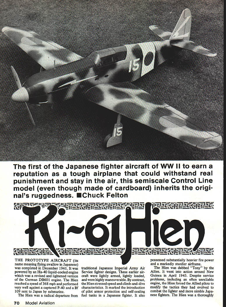
The prototype aircraft (its name meaning "flying swallow") was completed in December 1941. It was powered by an Ha-40 liquid-cooled engine, a revised and lightened version of the German DB 601 engine. The Hien reached a speed of 368 mph and performed very well against a captured P-40 and a Bf 109 sent to Japan by submarine.
The Hien was a radical departure from traditional Japanese Imperial Army Air Service fighter designs. Earlier aircraft were lightly armed, lightly loaded, and highly maneuverable. By contrast, the Hien stressed speed and climb-and-dive characteristics. It marked the introduction of pilot armor protection and self-sealing fuel tanks in a Japanese fighter. It also possessed substantially heavier firepower and a markedly sturdier airframe.
Dubbed "Tony" by the Allies, the Hien went into action around New Guinea in April 1943. Despite service problems, including an often unreliable engine, the Hien forced Allied pilots to modify tactics that had evolved to combat the lighter, more nimble Japanese fighters. The Hien was a thoroughly competent design in virtually every aspect. More than any other type, it was responsible for disproving the widely held belief that Japanese aircraft were "lightweights" incapable of taking punishment and surviving.
Model overview
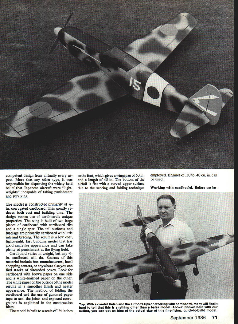
The model is constructed primarily of 1/8-in. corrugated cardboard. This greatly reduces both cost and building time. The design makes use of cardboard's unique properties: the wing is built of two large pieces of cardboard with cardboard ribs and a single spar; the tail surfaces and fuselage are primarily cardboard with little internal bracing. The result is a low-cost, lightweight, fast-building model that has good scale-like appearance and can take plenty of punishment at the flying field.
- Scale: 1 1/2 inches to the foot (wingspan 60 in., length 45 in.)
- Airfoil: bottom flat, curved upper surface formed by scoring and folding
- Power: engines of .30 to .40 cu. in. can be used
Cardboard varies in weight, but any 1/8-in. cardboard will do. Sources include box manufacturers, local shopping centers, or anywhere you can find stacks of discarded boxes. Look for cardboard with brown paper on one side and white-finished paper on the other; the white paper on the outside of the model yields a smoother finish and neater appearance. The method of folding the cardboard and the use of gummed paper tape to seal joints and exposed corrugations are explained below.
Working with cardboard
Before beginning, consider these special tips:
- Glue:
- Water-based white glue (Titebond recommended) is suggested for general assembly.
- Contact cement is recommended where a firm, instant bond is needed, since parts can be shifted while gluing.
- Scoring fold lines: use a creasing tool (handle with a 1-in. radius wheel). Run it along a straightedge to form the fold line.
- Sealing seams: use gummed paper tape, 1-in.-wide. Cut a thin strip to length, dip in water, and smooth over the seam.
Waterproofing cardboard
Waterproofing can be done to the raw material before cutting parts:
- Mix 25% clear polyurethane and 75% paint thinner (the cheaper varieties are fine).
- Thoroughly mix and brush the clear polyurethane mixture liberally onto the cardboard sheet.
- Allow to dry 48 hours.
This adds no appreciable weight and renders the cardboard completely waterproof. Treated cardboard yields crisp, clean, wood-like cuts, becomes a solid surface with no open corrugations, and is non-porous.
Finishing options:
- Easiest: three coats of color dope and two coats of clear dope.
- Other coverings: Solarfilm, MonoKote, vinyl, or paper are acceptable; however, a surface doped will result in a better bond at seams and joints.
- Exposed edges: cover with strips of gummed paper tape.
Construction (general)
- Cut out all cardboard and wood parts using the template outlines. Be sure to note the direction of the corrugations.
- Score and fold cardboard parts as indicated on the plans.
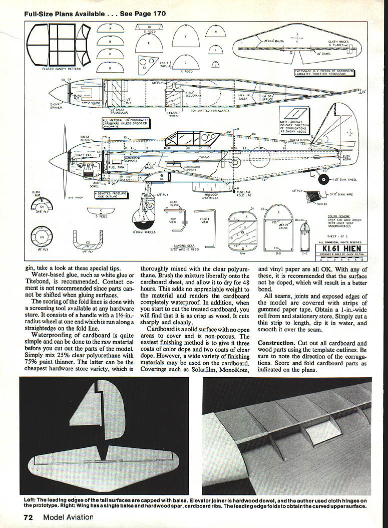
Tail surfaces
- Stabilizer, fin, rudder, and elevators: each made from two pieces of 3/16-in. cardboard laminated together cross-grained to give 1/4-in. surfaces.
- Add 1/8 x 1/4-in. balsa strip to the fin leading edge.
- Add 1/8 x 1/4-in. balsa strips to the stabilizer leading and trailing edges.
- Glue the elevators to the 1/4-in. dowel. Add 1/8 x 1/4-in. balsa strips to the remainder of the elevator leading edge. Round off all balsa edges.
- Seal all raw edges with gummed paper tape.
- Hinge the elevators to the stabilizer with cloth hinges at four places.
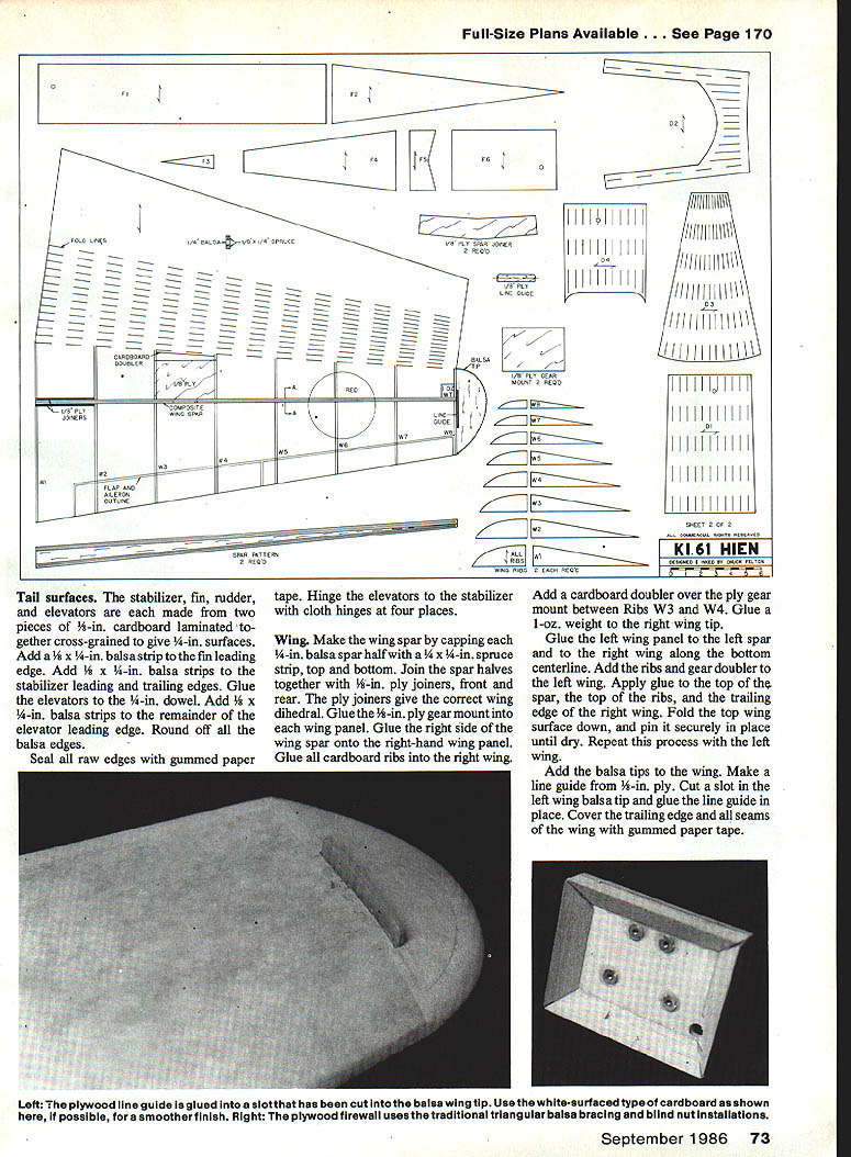
Wing
- Make the wing spar by capping each 1/4-in. balsa spar half with a 1/8 x 1/4-in. spruce strip, top and bottom.
- Join the spar halves together with 1/8-in. ply joiners, front and rear. The ply joiners give the correct wing dihedral.
- Glue the 1/8-in. ply gear mount into each wing panel.
- Glue the right side of the wing spar onto the right-hand wing panel. Glue all cardboard ribs into the right wing panel.
- Add a cardboard doubler over the ply gear mount between ribs W3 and W4.
- Glue a 1-oz. weight to the right wing tip.
- Glue the left wing panel to the left spar and to the right wing along the bottom centerline. Add the ribs and gear doubler to the left wing.
- Apply glue to the top of the spar, the top of the ribs, and the trailing edge of the right wing. Fold the top wing surface down and pin securely in place until dry. Repeat with the left wing.
- Add the balsa tips to the wing.
- Make a line guide from 1/8-in. ply. Cut a slot in the left wing balsa tip and glue the line guide in place.
- Cover the trailing edge and all seams of the wing with gummed paper tape.
Fuselage
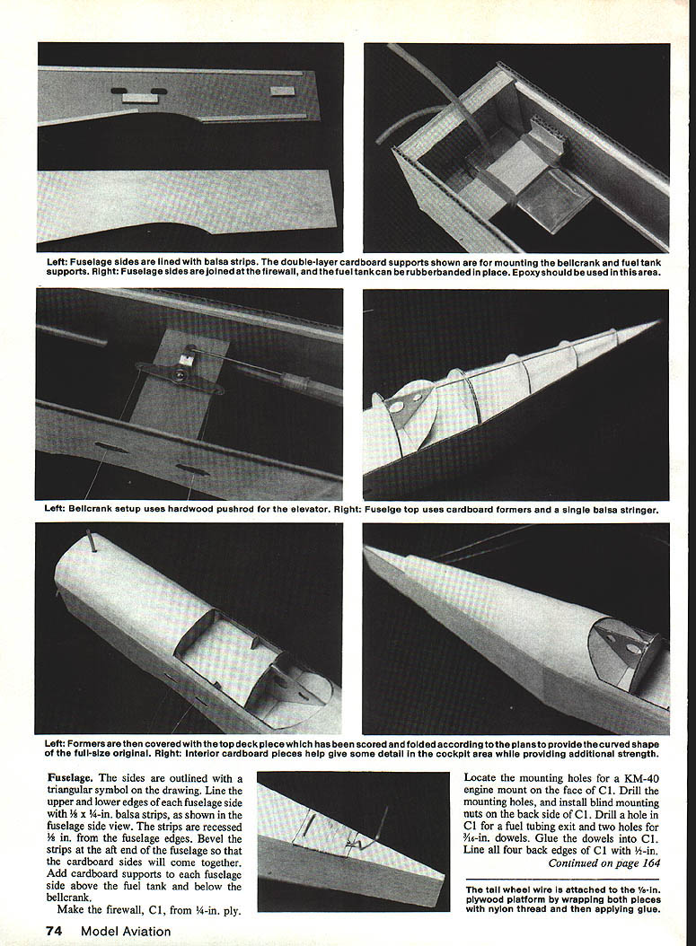
- The fuselage sides are outlined with a triangular symbol on the drawing.
- Line the upper and lower edges of each fuselage side with 1/8 x 1/4-in. balsa strips, recessed 1/8 in. from the fuselage edges. Bevel the strips at the aft end so the cardboard sides will come together.
- Add cardboard supports to each fuselage side above the fuel tank and below the bellcrank.
- Make the firewall C1 from 1/4-in. ply.
- Locate the mounting holes for a KM-40 engine mount on the face of C1. Drill the mounting holes and install blind mounting nuts on the back side of C1.
- Drill a hole in C1 for a fuel tubing exit and two holes for 3/16-in. dowels. Glue the dowels into C1.
- Line all four back edges of C1 with 1/8-in. balsa.
- Tail wheel wire: attach to the 3/16-in. plywood platform by wrapping with nylon thread and then applying glue. Add triangular balsa for bracing.
- Glue C1 to the right side of the fuselage. When dry, glue the left side of the fuselage to C1.
- Attach the fuel tank to the 1/4-in. ply support (tank may be attached with rubber bands).
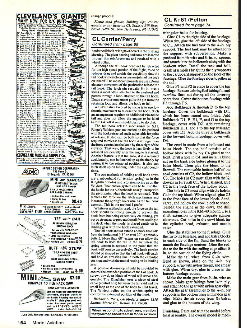
- Make a pushrod from 3/32-in. wire and 1/32-in. sq. spruce, and attach it to the bellcrank along with the lead-out wires.
- Install the tank and bellcrank assemblies by gluing the ply supports to the cardboard supports on the fuselage sides.
- Glue the fuselage sides together at the tail.
- Glue F1 and F2 in place to cover the top fuselage. Be sure to bring fuel tubing, fill, and overflow lines out during all covering operations.
- Cover the bottom fuselage with F3 through F6.
- Add bulkheads A through D to the top fuselage. Cover the bulkheads with D1, which has been scored and folded.
- Add bulkheads D1, E, F1, and G to the top fuselage; cover with D2.
- Add remaining bulkheads H, I, and J to the top fuselage; cover with D3.
- Add the three K bulkheads to the forward bottom fuselage; cover with D4.
Cowl:
- The cowl is made from a hollowed-out balsa block.
- Top half: hollow block with 1/16-in. ply C4 glued to the front. Drill a hole in C4 and install a blind nut on the back side before gluing it to the balsa block. Then glue the block to the firewall.
- Removable bottom half: consists of C2, the hollow block, and C3. The holes in C2 must align with the 3/32-in. dowels in firewall C1—when aligned, glue C2 to the back face of the lower block.
- The hole in C3 must align with the hole in C4 in the top block—when aligned, glue C3 to the front face of the lower block.
- Sand, carve, and hollow the cowl block to shape. Test-fit the cowl on the fuselage and mark mounting holes in the KM-40 mount. Use a shaft extension to give adequate spinner clearance.
- Cut holes in the cowl block for the cylinder head, exhaust, and needle valve.
Tail and gear:
- Glue the stabilizer to the fuselage. Glue the fin to the fuselage and add balsa blocks to each side of the fin; sand the blocks to match the fuselage contour.
- Glue the rudder to the fin with the trailing edge offset 1/16 in. to the outside of the flying circle.
- Make the tail wheel from 3/32-in. wire: bend as shown, place on the 1/8-in. ply support, wrap with nylon thread, smear with glue, and when dry glue in place in the bottom fuselage cutout.
- Make the main gear from 5/32-in. wire as shown. Make gear fairings from 1/8-in. ply and attach to the gear with nylon gear clips.
- Attach the gear assemblies to the 1/8-in. ply supports in the bottom wing with nylon gear clips.
- Make the air scoop from 3/16-in. balsa and glue to the bottom of the wing.
Finishing
- Paint and trim the model before final assembly.
- Overall finish: medium gray with dark green camouflage on the top.
- Fin and spinner: Curtiss blue.
- Lettering and trim: made from MonoKote. Aileron and flap outlines are black MonoKote.
- Roundels: red; the numbers: white.
- Canopy: make from thin plastic; epoxy-glue to the fuselage. Outline the canopy with thin strips of MonoKote.
- Exposed edges and seams: can be finished with gummed paper tape as needed.
Final assembly
- Glue the wing to the fuselage.
- Pass the lead-out wires through the wingtip line guide and tie them.
- Attach the nylon control horn to the elevator and hook up the pushrod.
- Attach 3-in. wheels to the main gear and a 1/2-in. wheel to the tail gear.
- Attach an 11 x 6 prop and a 2-3/4-in. spinner to the engine.
Your airplane is now complete. Be sure to balance the model at the point shown on the plans.
Transcribed from original scans by AI. Minor OCR errors may remain.

