
KLOUD KING
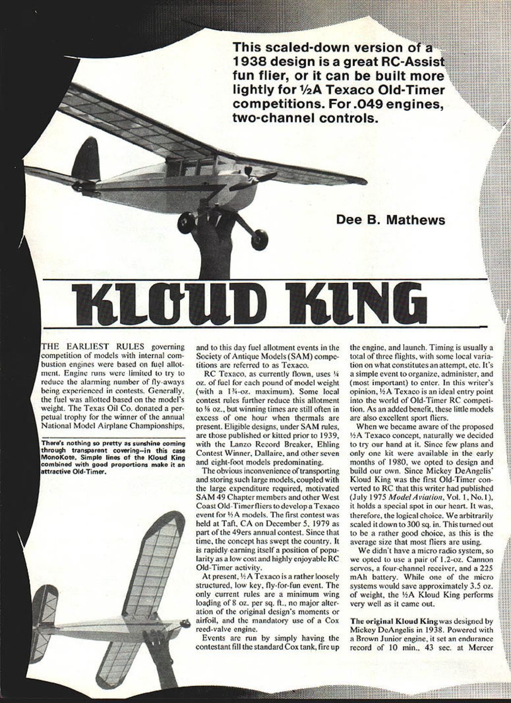
This scaled-down version of a 1938 design is a great RC-assist fun flier, or it can be built more lightly for 1/2A Texaco Old-Timer competitions. For .049 engines, two-channel controls.
Dee B. Mathews
The earliest rules governing competition of models with internal combustion engines were based on fuel allotment. Engine runs were limited to try to reduce the alarming number of fly-aways being experienced in contests. Generally, the fuel was allotted based on the model's weight. The Texas Oil Co. donated a perpetual trophy for the winner of the annual National Model Airplane Championships, and to this day fuel allotment events in the Society of Antique Models (SAM) competitions are referred to as Texaco.
RC Texaco, as currently flown, uses 1/4 oz. of fuel for each pound of model weight (with a 1 3/4-oz. maximum). Some local contest rules further reduce this allotment to 1/8 oz., but winning times are still often in excess of one hour when thermals are present. Eligible designs, under SAM rules, are those published or kitted prior to 1939, with the Lanzo Record Breaker, Ehling Contest Winner, Dallaire, and other seven- and eight-foot models predominating.
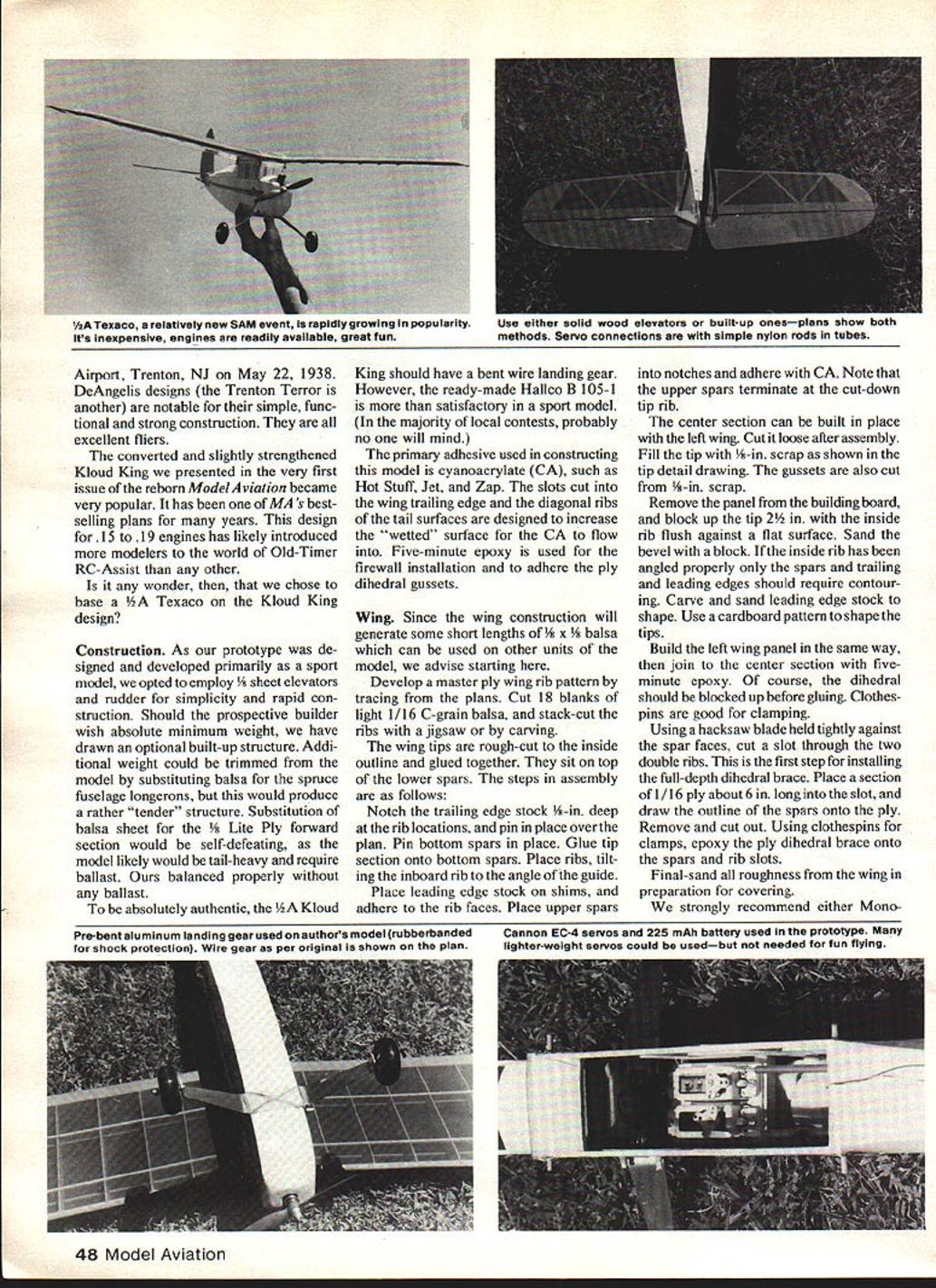
The obvious inconvenience of transporting and storing such large models, coupled with the large expenditure required, motivated SAM 49 Chapter members and other West Coast Old-Timer fliers to develop a Texaco event for 1/2A models. The first contest was held at Taft, CA on December 5, 1979 as part of the 49ers annual contest. Since that time, the concept has swept the country. It is rapidly earning itself a position of popularity as a low cost and highly enjoyable RC Old-Timer activity.
At present, 1/2A Texaco is a rather loosely structured, low-key, fly-for-fun event. The only current rules are a minimum wing loading of 8 oz. per sq. ft., no major alteration of the original design's moments or airfoil, and the mandatory use of a Cox reed-valve engine.
Events are run by simply having the contestant fill the standard Cox tank, fire up the engine, and launch. Timing is usually a total of three flights, with some local variation on what constitutes an attempt, etc. It's a simple event to organize, administer, and (most important) to enter. In this writer's opinion, 1/2A Texaco is an ideal entry point into the world of Old-Timer RC competition. As an added benefit, these little models are also excellent sport fliers.
When we became aware of the proposed 1/2A Texaco concept, naturally we decided to try our hand at it. Since few plans and only one kit were available in the early months of 1980, we opted to design and build our own. Since Mickey DeAngelis' Kloud King was the first Old-Timer converted to RC that this writer had published (July 1975 Model Aviation, Vol. 1, No. 1), it holds a special spot in our heart. It was, therefore, the logical choice. We arbitrarily scaled it down to 300 sq. in. This turned out to be a rather good choice, as this is the average size that most fliers are using.
We didn't have a micro radio system, so we opted to use a pair of 1/2-oz. Cannon servos, a four-channel receiver, and a 225 mAh battery. While one of the micro systems would save approximately 3.5 oz. of weight, the 1/2A Kloud King performs very well as it came out.
The original Kloud King was designed by Mickey DeAngelis in 1938. Powered with a Brown Junior engine, it set an endurance record of 10 min., 43 sec. at Mercer.
The converted and slightly strengthened Kloud King we presented in the very first issue of the reborn Model Aviation became very popular. It has been one of MA's best-selling plans for many years. This design for .15 to .19 engines has likely introduced more modelers to the world of Old-Timer RC-assist than any other.
Construction
As our prototype was designed and developed primarily as a sport model, we opted to employ 1/8-in. sheet elevators and rudder for simplicity and rapid construction. Should the prospective builder wish absolute minimum weight, we have drawn an optional built-up structure. Additional weight could be trimmed from the model by substituting balsa for the spruce fuselage longerons, but this would produce a rather "tender" structure. Substitution of balsa sheet for the 1/8-in. Lite Ply forward section would be self-defeating, as the model likely would be tail-heavy and require ballast. Ours balanced properly without any ballast.
To be absolutely authentic, the 1/2A Kloud King should have a bent wire landing gear. However, the ready-made Hallco B105-1 is more than satisfactory in a sport model. (In the majority of local contests, probably no one will mind.)
The primary adhesive used in constructing this model is cyanoacrylate (CA), such as Hot Stuff, Jet, and Zap. The slots cut into the wing trailing edge and the diagonal ribs of the tail surfaces are designed to increase the "wetted" surface for the CA to flow into. Five-minute epoxy is used for the firewall installation and to adhere the ply dihedral gussets.
Wing
Since the wing construction will generate some short lengths of 1/8 x 3/8-in. balsa which can be used on other units of the model, we advise starting here.
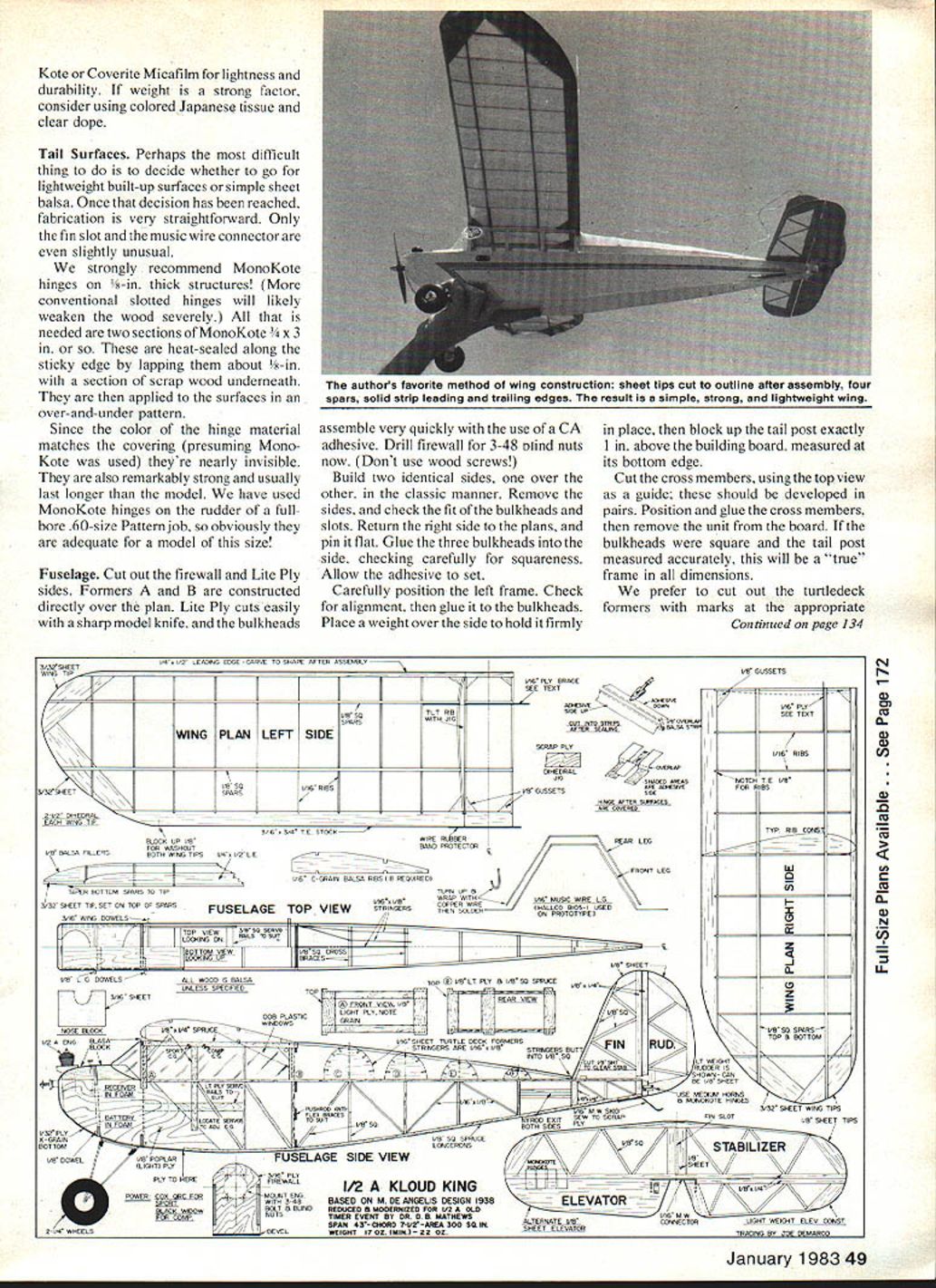
Develop a master ply wing rib pattern by tracing from the plans. Cut 18 blanks of light 1/16-in. C-grain balsa, and stack-cut the ribs with a jigsaw or by carving.
The wing tips are rough-cut to the inside outline and glued together. They sit on top of the lower spars. The steps in assembly are as follows:
- Notch the trailing edge stock 1/8-in. deep at the rib locations, and pin in place over the plan. Pin bottom spars in place.
- Glue tip section onto bottom spars. Place ribs, tilting the inboard rib to the angle of the dihedral.
- Place leading edge stock on shims, and adhere to the rib faces. Place upper spars into notches and adhere with CA. Note that the upper spars terminate at the cut-down tip rib.
The center section can be built in place with the left wing. Cut it loose after assembly. Fill the tip with 1/8-in. scrap as shown in the tip detail drawing. The gussets are also cut from 1/8-in. scrap.
Remove the panel from the building board, and block up the tip 2 1/2 in. with the inside rib flush against a flat surface. Sand the bevel with a block. If the inside rib has been angled properly only the spars and trailing and leading edges should require contouring. Carve and sand leading edge stock to shape. Use a cardboard pattern to shape the tips.
Build the left wing panel in the same way, then join to the center section with five-minute epoxy. Of course, the dihedral should be blocked up before gluing. Clothespins are good for clamping.
Using a hacksaw blade held tightly against the spar faces, cut a slot through the two double ribs. This is the first step for installing the full-depth dihedral brace. Place a section of 1/16-in. ply about 6 in. long into the slot, and draw the outline of the spars onto the ply. Remove and cut out. Using clothespins for clamps, epoxy the ply dihedral brace onto the spars and rib slots.
Final-sand all roughness from the wing in preparation for covering.
We strongly recommend either MonoKote or Coverite Micafilm for lightness and durability. If weight is a strong factor, consider using colored Japanese tissue and clear dope.
Tail Surfaces
Perhaps the most difficult thing to do is to decide whether to go for lightweight built-up surfaces or simple sheet balsa. Once that decision has been reached, fabrication is very straightforward. Only the fin slot and the music wire connector are even slightly unusual.
We strongly recommend MonoKote hinges on 1/8-in.-thick structures! (More conventional slotted hinges will likely weaken the wood severely.) All that is needed are two sections of MonoKote about 3/4 x 3 in. or so. These are heat-sealed along the sticky edge by lapping them about 1/8-in. with a section of scrap wood underneath. They are then applied to the surfaces in an over-and-under pattern.
Since the color of the hinge material matches the covering (presuming MonoKote was used) they're nearly invisible. They are also remarkably strong and usually last longer than the model. We have used MonoKote hinges on the rudder of a full-bore .60-size Pattern job, so obviously they are adequate for a model of this size!
Fuselage
Cut out the firewall and Lite Ply sides. Formers A and B are constructed directly over the plan. Lite Ply cuts easily with a sharp model knife, and the bulkheads assemble very quickly with the use of a CA adhesive. Drill firewall for 3-48 blind nuts now. (Don't use wood screws!)
Build two identical sides, one over the other, in the classic manner. Remove the sides, and check the fit of the bulkheads and slots. Return the right side to the plans, and pin it flat. Glue the three bulkheads into the side, checking carefully for squareness. Allow the adhesive to set.
Carefully position the left frame. Check for alignment, then glue it to the bulkheads. Place a weight over the side to hold it firmly in place, then block up the tail post exactly 1 in. above the building board, measured at its bottom edge.
Cut the cross members, using the top view as a guide; these should be developed in pairs. Position and glue the cross members, then remove the unit from the board. If the bulkheads were square and the tail post measured accurately, this will be a "true" frame in all dimensions.
We prefer to cut out the turtledeck formers with marks at the appropriate locations.
Transcribed from original scans by AI. Minor OCR errors may remain.

