
Koutny's P-51H
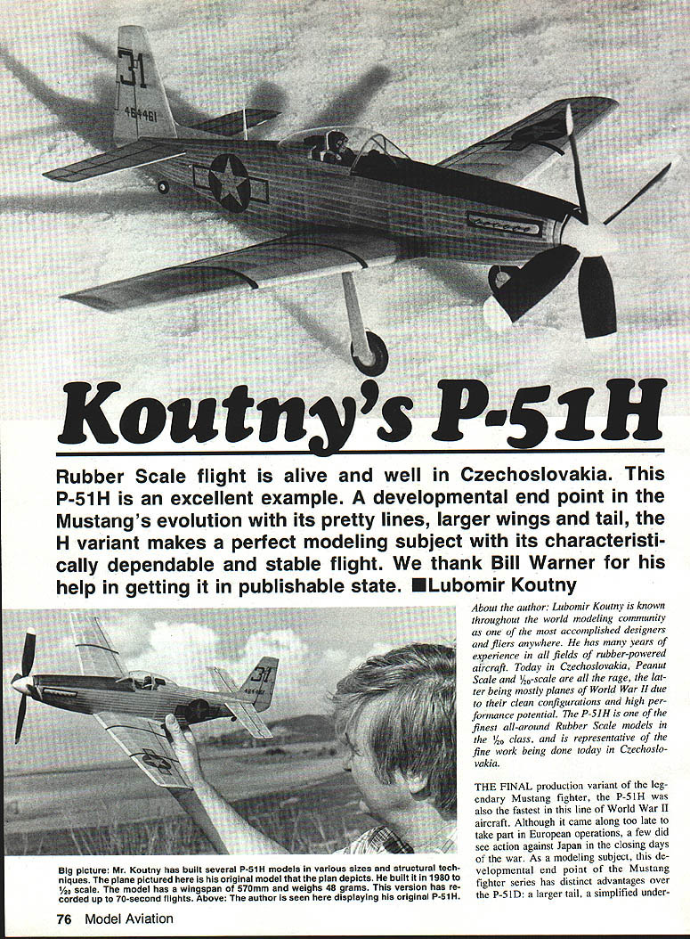
Rubber Scale flight is alive and well in Czechoslovakia. This P-51H is an excellent example — the developmental end point of the Mustang's evolution. Its pretty lines, larger wings and tail of the H variant make it a perfect modeling subject; its characteristically dependable, stable flight is notable. We thank Bill Warner for his help in getting it into publishable shape. — Lubomir Koutny
About the author
Lubomir Koutny is known throughout the world modeling community as an accomplished designer and flier. He has many years of experience in all fields of rubber-powered aircraft. In Czechoslovakia today, Peanut Scale and 1/2‑scale are all the rage, the latter being mostly World War II planes because of their clean configurations and high performance potential. The P-51H is one of the finest all-around Rubber Scale models in the 1/2 class and is representative of the fine work being done in Czechoslovakia.
The final production variant of the Mustang fighter, the P-51H was also the fastest in this line of World War II aircraft. Although it arrived too late to take part in European operations, a few saw action against Japan in the closing days of the war. As a modeling subject the P-51H has distinct advantages over the P-51D: a larger tail, a simplified undercarriage with smaller wheels, and a low-drag wing. Many Czech modelers have flown this scale model successfully when other 1/2‑scale ships were left in the box due to bad winds.
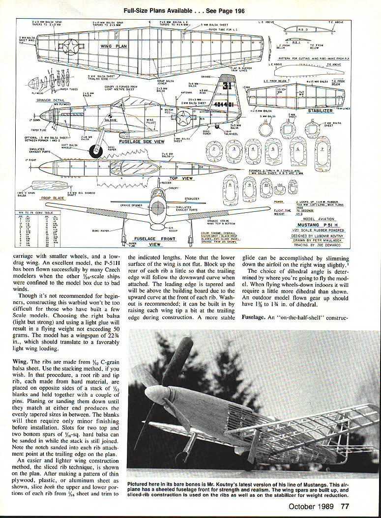
Choosing the right balsa (light but strong) and using a light glue should produce a flying weight not exceeding 50 g. The model has a wingspan of 22 3/4 in. (about 570 mm), giving a favorable light wing loading. It is not recommended for complete beginners, but construction will be straightforward for anyone who has built a few scale models.
Wing
- Ribs: made from 1/32" C‑grain balsa sheet. The stacking method may be used:
- Make root and tip rib patterns from hard stock and place them on opposite sides of a stack of 1/32" blanks.
- Pin the stack, plane or sand until the ends match, producing evenly tapered ribs.
- While the stack is joined you can sand slots for two top and two bottom spars of 1/16" square hard balsa.
- Note the notch sanded into each rib at the trailing-edge rib attachment point on the plan.
- Sliced-rib technique (easier and lighter):
- Make a pattern from thin plywood, plastic, or aluminum.
- Slice both the upper and lower portions of each rib from 1/16" sheet and trim to the indicated lengths.
- The lower wing surface is not flat: block up the rear of each rib slightly so the trailing edge follows the downward curve.
- The leading edge is tapered and will sit above the building board due to an upward curve at the front of each rib.
- Washout:
- Recommended; build it in by raising each wing tip a little at the trailing edge during construction.
- For a more stable glide, slim the airfoil on the right wing slightly.
- Dihedral:
- Choice depends on where you fly. Wheels-down indoor flight requires a bit more dihedral than shown.
- Outdoor gear-up flight should have about 1 1/2 to 1 3/4 in. of dihedral.
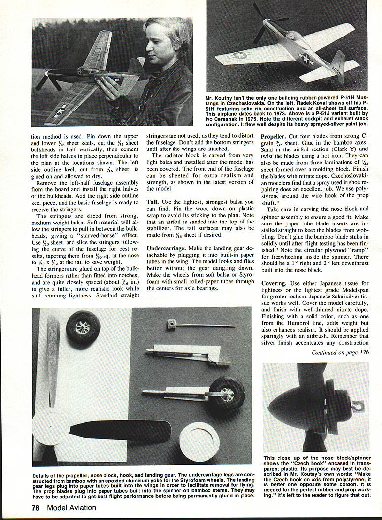
Fuselage
- Construction: on-the-half-shell method.
- Pin down the upper and lower 1/8" sheet keels on the plan.
- Cut the 1/32" sheet bulkheads in half vertically and cement the left-side halves in place perpendicular to the plan at the shown locations.
- Glue on the left outside keel (1/32" sheet) and allow to dry.
- Remove the left-half assembly and install the right-half bulkheads and right-side keel to complete the basic fuselage shell ready for stringers.
- Stringers:
- Slice from strong, medium-weight balsa (not soft or they will pull in between bulkheads).
- Use 1/32" sheet and slice following the fuselage curve for best results.
- Taper from approx. 1/32" square at the nose to 1/8" x 1/8" at the tail to save weight.
- Glue stringers on top of the bulkhead formers rather than fitting into notches; space them closely (about 3/32") for a fuller, realistic look without excess weight.
- Do not add bottom stringers until after the wings are attached.
- Radiator block: carve from very light balsa and install after covering.
- Front fuselage: may be sheeted for extra realism and strength; fit nose block and engine mount securely.
Tail
- Use the lightest, strongest balsa available.
- Pin tail parts down on plastic wrap to prevent sticking to the plan.
- The stabilizer has an airfoil sanded into its top surface.
- Tail surfaces may also be made from 1/32" sheet if desired.
- A small twist in the elevator (about 2 mm) is beneficial.
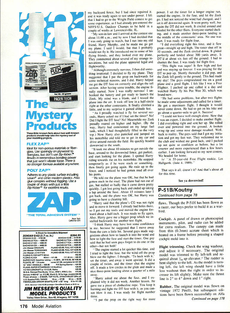
Undercarriage
- Make the landing gear detachable by plugging it into built-in paper tubes in the wing.
- The model looks and flies better without the gear dangling; fly gear-up outdoors when appropriate.
- Make wheels from soft balsa or Styrofoam with small rolled-paper tubes through the centers for axle bearings.
Propeller
- Blades: cut four blades from strong C‑grain 3/32" sheet. Glue in bamboo axles.
- Shape:
- Sand in an airfoil section (Clark Y) and twist the blades using a hot iron.
- Alternatively, make blades from three laminations of 1/32" sheet formed over a molding block.
- Finish blades with nitrate dope; Czechoslovakian modelers recommend a spray used in shoe repair for a good finish.
- Use polyurethane around the wire hook of the prop shaft.
- Carve the nose block and spinner carefully for a good fit. Note the circular plywood "ramp" for freewheeling inside the spinner.
- Blade inserts: make sure the paper-tube blade inserts are straight to prevent wobble. Do not glue bamboo blade stubs solidly until flight tests are finished.
- Thrust: there should be about 1° right and 2° left downthrust built into the nose block.
Covering
- Use Japanese tissue for lightness or the lightest grade Modelspan for greater realism. Japanese Sakai silver tissue works well.
- Cover carefully and finish with well-thinned nitrate dope.
- A solid color (e.g., Humbrol) enhances realism but adds weight; apply sparingly with an airbrush.
- A silver finish will accentuate any construction flaws.
Cockpit
- Add drawn or photocopied instrument panels, pilot, and radio for realism.
- Make the canopy from thin acetate (about 0.3 mm) heated and pressed over a shaped mold.
Flight trimming
- Balance point: ensure the center of gravity is as shown on the plan (on a line with the front of the cockpit). Add weight to nose or tail as needed.
- Test glide:
- Try a test glide in high grass, aiming the nose slightly down.
- A good glide should cover about 12 yards (11 m) in a straight line or with a gentle left turn.
- If it stalls or dives, check the rubber position (it may bunch and shift CG).
- Maiden flight:
- Wind rubber about 250 turns for the first flight. The model should fly gently leftward and may climb slightly.
- If it stalls under power, add a little more downthrust (thin shim between top of nose block and motor peg).
- If maiden is satisfactory, increase to 500 turns. Expected behavior: climb to the left and glide to the right.
- If it climbs in the first half of the circle and descends in the second, add washout in the right wing and recheck glides.
- Once the glide is acceptable, increase to 800–1,000 turns. The airplane should climb easily to over 150 ft (45 m).
- Adjustments:
- Make only one minor correction between flights.
- For improved glide stability, ensure the right wing tip has a slightly slimmer airfoil than the left (per Koutny's note).
Rubber and power
- Original: vintage 1972 Pirelli was used; later models have flown successfully on other rubbers (Romeo, Fiat, etc.) with flight times of 60–75 seconds in calm air.
- Lubricant: straight castor oil is used.
- If using modern contest or FAI rubber, start with three loops of 3 mm (1/8") about 28 in. long; actual amount depends on model weight and propeller pitch.
- Engine guidance from Koutny (footnote): "12g FAI rubber, 6 x 1/4 x 3/32 in. for flight without undercarriage, or 8 x 1/4 x 3/32 in. for ROG."
Flying
- Check balance and trim per the plan before powering up.
- For trimming: the original model was trimmed to fly slightly left; about 1/8 in. up elevator and a slight left rudder were used.
- As the model turns left, the left wing should have a little less washout than the right to increase lift slightly on the left side.
- Thrust line recommendation: about 2° to 4° down and 1° right (adjust as needed for your model).
To the reader
In preparing this text, effort was made to convey Mr. Koutny's words as clearly as possible. Although his English is very good, some phrases may be less than crystal-clear to the average modeler. Examine the photos and plan carefully to clarify details, and feel free to write to Mr. Koutny with questions or to tell him about your model.
Contact: Ing. Lubomir Koutny Zabrenska 33 616 00 Brno Czechoslovakia
— Bill Warner
Footnotes
The following notes are presented in Mr. Koutny's exact words:
- "For a better gliding stability is good if the right half of wing (tip) has some slimmer aerofoil opposite the left."
- "Make the Czech hook on axis from polystyrene, it is better one opposite some cordon. It is needed for the perfect rubber and prop working."
- "Make a pattern for the correct blade angle's adjustment pitch in 0.160mm is 350mm."
- "It is very good if the elevator has a little twist (2mm is enough)."
- "Engine: 12g FAI rubber, 6 x 1/4 x 3/32 in. for flight without undercarriage, or 8 x 1/4 x 3/32 in. for ROG."
Transcribed from original scans by AI. Minor OCR errors may remain.

