
Krackerjac Mk. I and Mk. II
Bill Winter with Bill Evans
VOICE OFFSTAGE: Here we go again!
Our favorite odd-couple design team is back—this time with a two-for-one. If you like options when you build, this RC sport plane/trainer combo is for you. The Mark I soars delightfully, and its higher-performance sibling gets excellent marks in hot-dogging.
From opposite schools of design, our coauthors have managed a second (and last, one presumes) unlikely collaboration. West Coaster Evans, who loves straight-up and 140°-plus flybys, is known for his philosophy that horizontal tails are tantamount to buggy-whip technology. East Coaster pre-historic old-timer Bill Winter is a go-slow airplane watcher who thinks that straight-up folks harbor hidden rocketry complexes.
Still, they found middle ground and produced the Krackerjac Mk I and Mk II.
When asked why Evans would stoop to building a conservative cabin job with a conspicuous stabilizer, Winter would only say, "What's a nice guy like Bill Evans doing in a place like this?" The two had collaborated on the Simitar Slow Motion (published January 1987, Model Aviation), a docile flying wing almost as easy to fly as an Eaglet. Evans was flabbergasted at Winter's responsiveness to that project. Winter, however, imposed conditions:
- The model had to soar — speed range ~15 to 80 mph.
- It had to be fully controllable on either rudder or ailerons — hence elevons.
- The fuselage was extended about eight inches behind the bobtail trailing-edge termination to the rudder post.
- Modest dihedral was added for extended hands-off flying.
- A tail-dragger arrangement to save weight.
- Aerobatic capability with a K&B Veco .19 as maximum power; later versions used O.S. .15, .40, or .60 engines depending on the mark and builder.
Winter and Evans produced two different-performance versions: the conservative, soaring-capable Mk I (Winter) and the higher-performance, aerobatic Mk II (Evans).
History and background
Winter: In 1960 full-house control systems had been around for a few years, but many could afford only single-channel escapement airplanes. Without elevator control, designers relied on "ballooning" turn-ins into the wind and fly-aways were common. The original 54-in. Krackerjac ("K") was rudder-only with quick-blip throttle (Max .15) and ended much of that nonsense. It was published in Air Trails and kitted by Jetco. The thin airfoil with a long Phillips entry was the secret of the model's controllability: excellent penetration and perfect touch-and-goes.
Of all my RCs over a 40-year period, three continue to be built: the Antique RC Special (published 1948); the early-60s Krackerjac; and the reed-systems low-wing Rookie. Other modelers have frequently improved these designs and continue to build them.
Several years ago I obtained a 6-ft version of Krackerjac for .40 power from a plans service. I built it and flew a dozen test flights. The wing was so efficient (about 6½ sq. ft. at ~7¼ lb. gross weight) that, like a glider, it was difficult to get it on the ground on a 300-ft strip. With a .40 it took off and climbed on one-third throttle, could fly inverted and respond to steering on half throttle, and performed consecutive outside loops at half throttle and one-third down elevator. A magazine wanted more power (a 1.20!), which I thought unnecessary; the aircraft was eventually given to Doug Pratt, who flew it with an Enya .46 four-stroke for three seasons.
Evans: Curiosity killed the cat. Even though I find horizontal tails to be useless appendages, Winter's short-coupled fuselage with its big stab had odd appeal. I could build one my way and fly it within a week. I simplified the fuse and made a foam, balsa-skinned wing and stab. It isn't neutrally stable as I prefer (Winter won't give up a measure of hands-off control), but it otherwise flies great. I shipped my version to Winter; UPS later stress-tested the wing and found it wanting, which led to a revised joiner and construction details.
Plans and naming
Winter and Evans agreed to present Winter's version as the Mk I and Evans' as the Mk II. The plans include many options and cross-features, allowing at least four different builds from the same set of drawings. The editor authorized two large plan sheets (40 x 52 in.) to accommodate the details.
Which to build? Here’s what to expect from each Mark.
Design Objectives — Mk I
Design objectives for the Mk I:
- Easy piloting — handling similar to a .40-powered Senior Falcon, Sig Kadet, or Goldberg Eagle.
- Ability to groove well in all maneuvers; better-than-average aerobatic potential.
- Enough reaction time so the airplane won't get ahead of the average pilot.
- Slow landing and automatic takeoff (despite being a tail-dragger).
- Ability to ride weak lift and thermal soar.
- Flying characteristics between a trainer and an intermediate ship.
Key performance notes:
- Low wing loading (~19 oz./sq.ft) and low drag sustain open maneuvers at relatively low power.
- Hands-off stability makes for relaxed flying.
- A .60 two-stroke is the upper practical limit; most aerobatics are done at partial throttle. A potent four-stroke (e.g., Enya .46 or Enya .60) works well — watch the CG with heavier engines.
- Careful building can yield a gross weight near 7 lb; Winter’s example was 7¼ lb with spoilers and two extra servos.
- Because the wing is lightly loaded and efficient, long, low approaches are necessary; spoilers are recommended as an option for short fields.
Evans on the Mk II
- The Mk II is much faster and more spectacular than the Mk I.
- The Mk II is closer to neutral stability but still safe hands-off; Winter specified two degrees of dihedral for a bit of extra stability.
- Evans’ foam, balsa-skinned wing weighs the same as Winter’s open-frame Mk I wing; his total model weight was ~7¼ lb.
- The Mk II is robust, higher-performing, and suitable for pilots with aileron experience. It can still be flown on rudder if necessary.
Construction
Fuselage
Two assembly techniques to ease construction:
- Flat bottom assembly
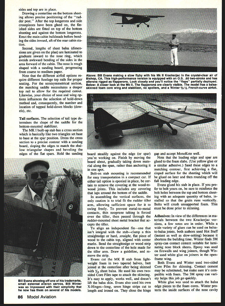
- The bottom sheeting is laid flat on the workbench. Evans used 1/2-in. soft sheeting with grain running lengthwise for the bottom, then glued 1/4-in.-sq. bottom longerons and crosspieces on top.
- The sheeting isn't trimmed until the fuselage sides and bottom are shaped and glued together.
- Draw a centerline on the bottom sheeting to position the rudder post precisely.
- After gluing top longerons and side crosspieces, fit the finished sides on top of the bottom sheeting and against the bottom longerons.
- Erect the main cabin bulkheads before bending the sides inward aft of the rear cabin station.
- Laminated nose-build
- Laminate lengths of sheet balsa (dimensions on plan) to graduate inward to the nose ring, avoiding awkward bending forward of the cabin.
- Rough-shape the nose with a sanding board progressing from coarse to medium paper.
Notes:
- Different airfoil options require different fuselage top rails for proper wing seating. The semisymmetrical section needs a deeper saddle cutout.
- Your choice of nose and wing options affects the hold-down method and number/location of tapped hold-down blocks (dowels).
Tail surfaces
- Tail type selection determines the saddle shape for a bottom-mounted stabilizer.
- Mk I built-up stab cross section is like two triangles set base-to-base at the spar position. Dress to contour with a sanding board.
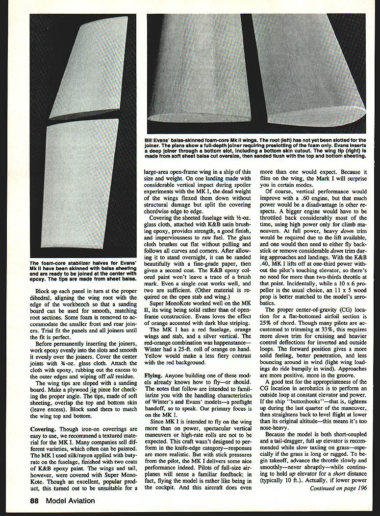
- Bolt-on stab mounting is recommended for compact transport. If epoxying the stab in place, remove covering at wood-to-wood joints.
- Trial-fit the rudder tiller arm to allow free swing; cover metal-to-metal contact with thin neoprene tubing over the tiller where it passes through the rudder-mounted bracket.
- To align an independent fin, clamp a thin straightedge to the cabin top aligned with center marks, bend it down to the centerline of the tiller hole, draw a guideline, and remove the straightedge.
Evans’ technique for Mk II stab:
- Cut stab from lightweight foam in two tapered halves, join at the centerline, and skin with 1/16-in. balsa using two-sided Core-Film tape.
- Glue leading edge and spar to foam slabs (use yellow glue), sand to matching contour, then round the leading edge.
- If you prefer bolt-on, reinforce bolt holes between top and bottom sheeting with vertical-grain balsa prior to skinning (bolts can crush unsupported foam).
Adhesives
- Hot Stuff (instant and slow-setting CA) was used by both authors to speed build time.
- 3M spray-can contact cement is good for laminating nose block sheets (Winter).
- Epoxy for firewalls and wing joiners (Winter sometimes used white glue on joiners in the open-frame wing).
- Two-sided Core-Film for skinning; contact cement can substitute but check foam compatibility.
- White glue to attach balsa edge pieces to foam cores.
- Winter protects inside nose cavity surfaces with epoxy.
Landing gear
- Any standard metal gear is satisfactory. Original used a Great Planes gear (wider and tougher); Hallco in appropriate size may be a bit flimsy on rough landings.
- Both legs are bent with slight toe-in to eliminate erratic takeoff runs.
- Recommended maximum: two degrees of toe-in and two degrees of caster. A bench vise can twist standard gear to these angles.
- Attach gear with either two 1/4-in. nylon bolts into blind nuts or with four self-tapping screws. Nylon bolts will shear in semi-crash landings; broken remnants can be removed by heating a screwdriver tip.
- (Newer Klett plastic gear medium size was later recommended.)
Mk I wing (open-frame)
- Can be built with or without spoilers.
- Airfoil has a long Phillips entry on the bottom near spar position, with a flat aft portion — easy to assemble on the bench.
- Block up the leading edge during assembly to ensure alignment.
- Use standard glue or epoxy on joiners; if spoilers are installed, spar webs in the spoiler area are placed forward so they clear the spoiler horn.
- Plans show bellcrank and linkage sizes and alignment for the spoiler servo. If your servo arm travel differs, use different servo arm holes rather than changing spoiler horn spacing.
- Washout for Mk I is achieved by bottom-sanding with a board in the tip area as shown on the plan.
- Spars and joiners should be epoxied and center joints covered with 3/4-oz. glass cloth attached with epoxy and rubbed out flush.
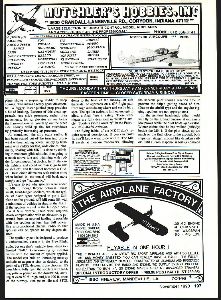
Mk II wing (foam, balsa-skinned)
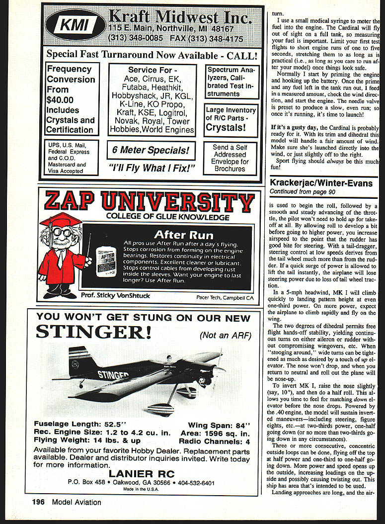
- Built from foam cores skinned with 1/16-in. balsa sheeting. Airfoil is an approximate 1/4–2/3 semisymmetrical section at less incidence than Mk I.
- Core-Film tape and X-hinges used; Robart hinges are a viable substitute (installed with epoxy).
- Ailerons should be fashioned from the lightest possible balsa because they are thick.
- Leading edge built in two pieces: inner piece glued to foam, sanded before skinning, then the outer leading edge glued after skinning.
- Joiner: use full-depth 3/16-in. ply joiner cut to foam depth. Tapered portion may leave a slot gap to be filled with epoxied scrap foam or microballoons mixed with epoxy.
- For outboard servos, thread leads through a short paper tube buried in the foam before skinning; an optional single-servo installation is shown for those who prefer it.
- Block up panels to proper dihedral and align roots to use a sanding board for matching root sections. Remove some foam to accommodate smaller front and rear joiners if needed.
- After fitting, work epoxy into joiner slots evenly and cover center joints with fiberglass cloth and epoxy.
- Wing tips: slope with sanding board, make a plywood jig for angle checking, and make soft-sheet tips that overlap skins; block sand to match.
Covering and finish
- Textured coverings are recommended for Mk I open-frame wing. Winter used silk/rayon on the fuselage (attached with butyrate) and finished with K&B epoxy paint. Wings and tail used Super MonoKote but this proved unsuitable on a large open-frame wing (it split chordwise during a heavy landing with spoilers).
- Covering the sheeted fuselage with 1/2-oz. glass cloth attached with K&B satin brushing epoxy provides strength, a good finish, and fuel resistance. The cloth sands nicely; two coats of epoxy paint finish well.
- Super MonoKote works well on Mk II’s solid wing; Evans liked orange with dark blue striping.
- Typical color schemes:
- Mk I: red fuselage, orange wings and stab, silver vertical.
- Mk II: orange accents with dark blue striping (per Evans).
Flying
These notes familiarize you with handling characteristics; primary focus is on the Mk I.
General handling (Mk I)
- Mk I is intended to fly on the wing more than on power. Spectacular vertical performance or high-rate rolls are not its forte; responses are realistic and precise.
- Vertical performance improves with a .60 engine, but excessive power defeats the design’s intentions. A larger engine must be throttled down most of the time, requiring significant trim changes.
- With a K&B .40, Mk I lifts off at one-third power without touching elevator; two-thirds throttle is usually more than enough for aerobatics. Prop selection: 10x6 typical; 11x5 is often better for aerobatics.
- Proper CG for a flat-bottomed airfoil: 25% of chord. Many pilots trim at 33%, but that increases down trim for cruising and heavier control deflections for inverted/outside loops. Forward CG gives better penetration and steadier handling in wind.
- Test for CG in aerobatics: perform an outside loop at constant elevator and power. If the ship "buttonhooks" (tightens during the last quarter then levels at a lower altitude), it’s too nose-heavy.
Takeoff and taxi
- Because the model is short-coupled and a tail-dragger, hold full up elevator while slow taxiing or pre-takeoff.
- Begin the takeoff roll at lower power, then smoothly advance throttle while maintaining up elevator for a short distance (typically ~10 ft). Allow a bit of roll development before going to higher power so rudder effectiveness increases; avoid instant surges that lift the tail and reduce tail-wheel steering traction.
Climb and cruise
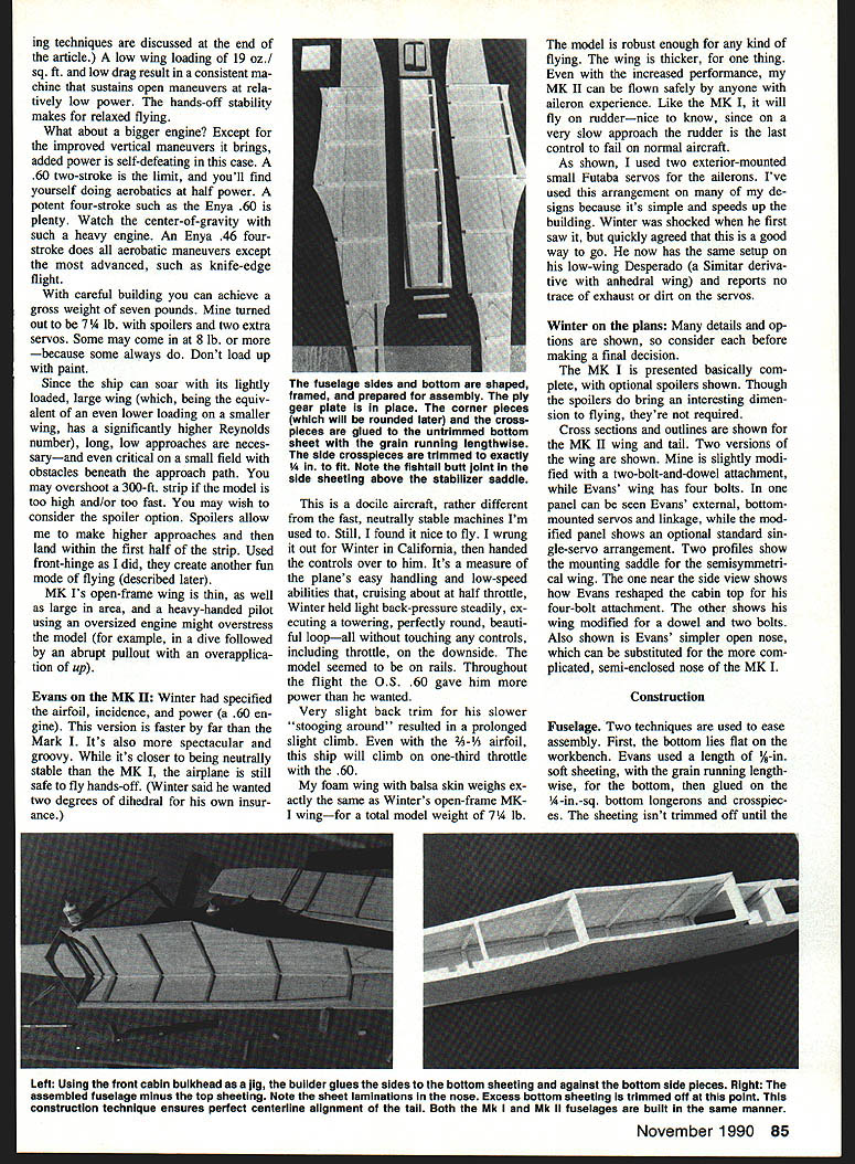
- In a 5-mph headwind, Mk I climbs to pattern height at one-third power. On more power, it climbs rapidly and flies on the wing.
- Two degrees of dihedral permit hands-off continuous turns on either aileron or rudder without compromising wingovers. Wide turns can be tightened with a touch of up elevator; nose won’t drop and neutralizing elevator returns the plane to nose-up attitude.
Inverted and outside maneuvers
- To invert Mk I: raise the nose slightly (~10°) and do a half roll to allow time to feel for down elevator; Mk I will sustain inverted maneuvers at two-thirds throttle with the .40 engine.
- Three or more concentric outside loops are possible: fly off the top at half power and use one-third to one-half power going down. More power increases loading on the up-side and can cause twisting out if excessive.
Approaches and landings
- Approaches are long. Use stick pressure, not abrupt movements, during flare. Slowly build sink for touchdown by gradually increasing up pressure.
- The plane shows a surprising tendency to keep coming—good for idle descent in tail. A larger, lower-pitched propeller provides some braking.
- Spoilers (optional on Mk I) are useful for short-field landings: front-hinged blade-type spoilers kill lift with modest drag buildup. Full-open spoilers (~60°) require steady up-elevator compensation. A proportional channel allows variable spoiler deployment and go-arounds with partial spoiler opening.
- Spoilers can produce a dethermalized descent adjustable from slight to a limited full effect; compensating up elevator varies with spoiler amount. This allows STOL-like approaches or steep approaches from altitude with a safe final flare. See Winter’s "Spoilers (with Power?)" (Model Aviation, Feb 1986) for full techniques.
Soaring
- Mk I soars easily. Typical technique: climb to moderate glide altitude, set throttle to a notch above idle, and trim with rudder for flat continuous circles. In lift, the circle tightens and speed increases; go to idle or shut off and the model glides. Use rudder trim to dress circle diameter until it locks in.
Mk II flying
- Mk II flying habits are similar but it excels at close-in maneuvers and higher-speed aerobatics. It can be flown safely by anyone with aileron experience and, like Mk I, will respond to rudder-only control if necessary.
Notes on radio and controls
- Use a proportional-channel radio for spoilers and precise control.
- Evans used two small exterior-mounted Futaba servos for the Mk II ailerons; this speeds building and has worked well with no exhaust/dirt problems reported. A standard single-servo arrangement is shown as an option on the plans.
Epilogue
When Evans shipped the Mk II to Winter, the stab was taped off with a note: "Leave this off; it flies better without it." Winter joked that if Evans weren't spoofing he would have used ailerons as elevons and reflexed them up for neutral control with CG at 20%.
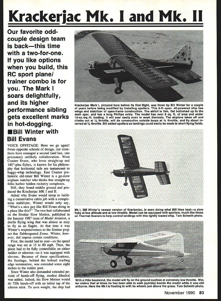
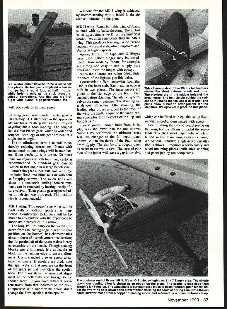
The Mk I pictured before its first flight was flown by Bill Winter a couple of years before being modified with spoilers. The 6-ft-span, .40-powered ship has open-frame wing and stabilizer construction, a thin flat-bottom airfoil with a long-Phillips entry, and over 6 sq. ft. area at under ~19 oz/sq.ft loading — allowing easy soaring in weak thermals. The aircraft takes off and climbs at one-quarter throttle, will do consecutive outside loops at full throttle, and fly inverted at half throttle. Spoilers make short-field landings easy.
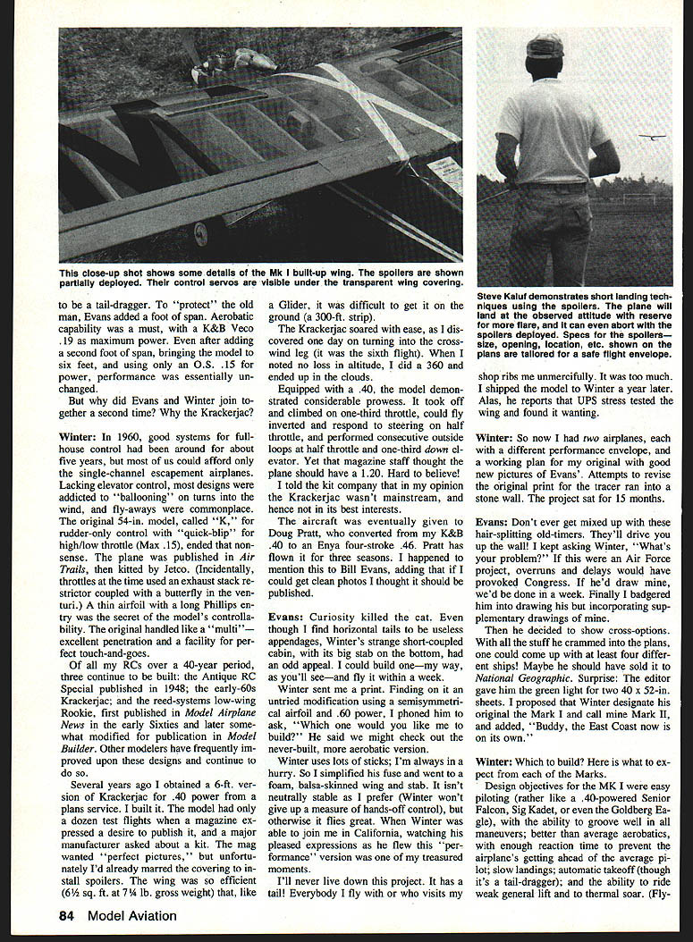
The Mk II, Evans' version, is seen doing what Evans likes best: slow flybys at low altitude on low throttle, and more spectacular aerobatics at higher throttle. Both Marks demonstrate that thoughtful design compromises can yield distinct, enjoyable flying experiences: one optimized for soaring and relaxed handling (Mk I), the other for higher performance and aerobatic flair (Mk II).
The original Krackerjac dates from the late 1940s and early ’50s. Over the decades the design has appeared in several publications and been adapted repeatedly by modelers. The two Marks presented here continue that tradition of practical, versatile RC design.
Transcribed from original scans by AI. Minor OCR errors may remain.

