
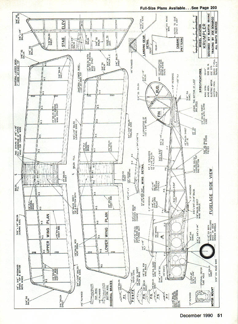
Krumpler
By Martin Irvine
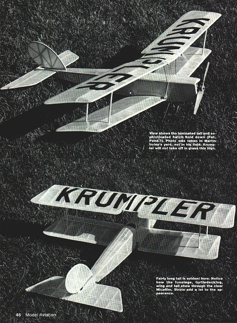
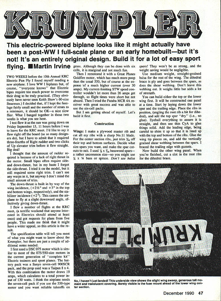
An electric-powered biplane that looks like a post‑WW I full‑scale or early homebuilt is actually an original design built for easy sport flying.
Two weeks before the 10th Annual KRC Electric Fun Fly I found myself needing a new airplane. I love biplanes, of course. Electric bipes require extra power to overcome drag, so I kept the fuselage fairly small and the number of struts to a minimum to make a nice slow flier. What I banged together in two weeks is what you see here. I test‑flew it as the sun was going down Friday, September 15 — 11 hours before leaving for the KRC meet.
It did not fly perfectly off the board; it required about three‑quarters right rudder and two clicks up elevator trim before it flew straight. The rudder was required mainly because of lack of right thrust from the motor; small bipes often require side and down thrust. I omitted side thrust in my haste, but I did build in down thrust by setting wing incidence (about 2° on the top wing and 3° on the bottom) and a stabilizer incidence of about 2°. I flew several flights at the KRC meet — a terrific weekend — and got requests for plans from several people, which suggested the Krumpler might have wider appeal.
A few notes before we build: I initially used a DSC .075 motor (similar to modern .075/.550-size motors) and a Sanyo seven‑cell 900SCR battery pack. Prop was a Taipan 8×4. That combination drew about 19 A and produced roughly 130 W. For reliable grass takeoffs with a 550-type motor I recommend a seven‑cell pack; six cells are marginal. I later remotored with a Great Planes Goldfire (more powerful than a 550); currents exceeded 30 A and flight times were very short. I also had success with a Futaba MCR‑4A receiver, which allowed use of six‑cell packs.
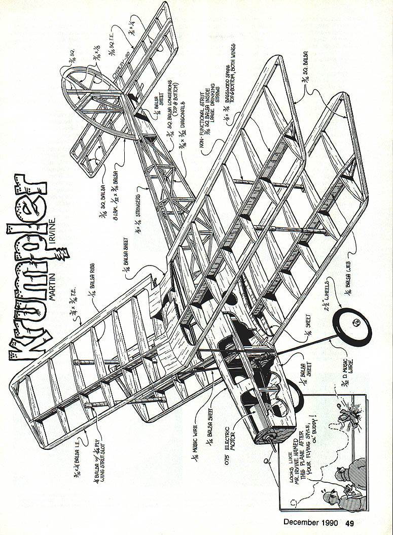
Construction
Wings
- Make a plywood master rib and cut ribs sharply with a No. 11 blade. For center‑section ribs, trim about 1/16 in. off the top and bottom surfaces.
- Decide on spar sizes and make spar cutouts to suit. I used 3/8 × 3/16 in. basswood spars (you can use 3/8 × 3/16 in. bass spruce). Do not use balsa spars — they lack strength and the weight savings are negligible.
- Use medium‑weight, straight‑grained balsa for the remainder of the wing.
- The dihedral bracing ply goes between the spars and acts as shear webbing. Don’t omit this webbing — it weighs little and adds a lot of strength.
Build one wing panel at a time:
- Lay down the lower spar and the trailing edge.
- Place ribs in position, angling the root rib slightly for dihedral.
- Add the top spar "dry" (no glue) to check alignment, then glue solidly with thin CA once everything is straight.
- Add the leading edge, shim as necessary so top and bottom of the ribs line up.
- Glue on wing tip pieces, add vertically grained shear webbing between spars, and brace the trailing edge with gussets.
- Cut slots in the root ribs for the dihedral brace.
Join the two wing halves with epoxy, allowing time for adjustments. Aim for approximately 1 in. per side dihedral on the top wing and about 1/2 in. per side on the bottom wing (adjust as required). Add the center‑section sheet and the center trailing/leading‑edge pieces (about 1/8 in. sheet is suitable); note that spars must be flush with the covering — don’t sheet over the strut fittings. Notch the center sheet for interplane struts and back it with ply where required; butt‑glue to the side ribs for strength.
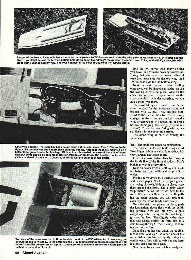
Bottom hatch and motor mounting
- To help balance, place the motor battery at the aft end of the hatch. Glue two 5/16‑in. square strips to the bottom of the hatch spaced to cradle the power pack.
- Add a wire yoke glued to the rear of the hatch and an angled dowel at the forward end. The battery sits between the wood strips and is held by a #64 rubber band stretched between the yoke and dowel.
- The hatch itself can be retained with a #32 rubber band looped over the hatch and the forward wing dowels — crude but effective.
- Mount the motor on a bulkhead; under the motor is a suitable location for a speed controller (fuse it if desired).
- Four notches in the sides of the hatch clear the cabane struts when fitted.
Tail
- The stabilizer is straightforward; the fin and rudder were built using a lamination technique:
- Cut a 1/4‑in. balsa form to the inside outline of the fin and rudder.
- Cut seven strips of soft 1/32 × 1/4 × 24‑in. balsa and one slightly wider strip.
- Pin the form to waxed paper. Stack the strips and wrap them around the form, wider strip next to the form to act as a dam.
- Pin and tension the laminations, then glue the stack with thin CA, being careful not to glue to the form.
- After curing, unpin, glue the other side, and spring the outline free to check for any spots needing more glue.
- Sand to the outline, leave the leading edge a little long to act as a key in the fuselage, then cut the rudder face and assemble to the plan.
This laminated method is strong and attractive.
Fuselage
- Construct both basic sides from 3/16‑in. square and sheet. Build the second side over the first using small pieces of wax paper at glue joints to prevent sticking.
- Make the right side about 1/8 in. shorter than the left to provide built‑in side thrust.
- Cabane strut mounts: glue slotted balsa pieces into the fuselage sides. Dry fit, then groove them to accept 1/16‑in. spring steel cabane wires before final gluing. Ensure slots face the inside of the fuselage.
- Groove the upper longerons to accept the cabanes and add a 1/16‑in. sheet doubler on the inside of both sides. This doubler stops short of the motor bulkhead to allow insertion later.
- Fill the forward two bays with 3/16‑in. sheet. Add 1/8 × 3/8‑in. strips at the tail end and let in 1/16‑in. sheet on the outside of the fuselage.
- Assemble the fuselage upside down on the building board with the forward upper longerons flat. Install temporary and permanent crosspieces as shown on the plan to square the box. Check squareness carefully.
- Pull the forward fuselage together and install the motor bulkhead. Draw the rear fuselage together, join and check straightness. Add remaining crosspieces.
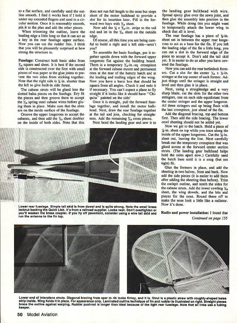
- Bend the landing gear, sew it to the landing gear bulkhead with wire, spread epoxy over the sewn joint and sand flush into position in the fuselage. Temporarily attach the lower wing to check levels.
- Fit a 1/8‑in. sheet between the upper rear longerons to act as a base for the fin. If the fin’s leading edge was left long, cut a slot in this piece to accept it.
- Add the rear turtledeck formers. Cut slots for the center 1/4 × 1/2‑in. stringer at the top center of each former, adjust and glue the stringer in place.
- Cut slots for the other two stringers using a straightedge and sharp blade; they should be equidistant from the center stringer and the upper longeron and flush with the aft crosspiece just ahead of the fin.
- Add diagonal bracing (top and bottom first, then sides). Defer lower cowl sheeting until later.
- Hatch: trace a piece of 1/8‑in. sheet on top to the inside of the upper longerons and cut it out. Remove the temporary crosspiece previously glued across the forward center section. Sand the hatch base until it’s a snug fit.
- Glue formers in place and add sheeting in two halves (front and back). Add side pieces, trim the cockpit outline, notch sides for cabane struts, fit lower cowling 1/16‑in. sheet, wing dowels, and nose shaping. Round off the nose to resemble a radiator if desired.
Radio and power installation
- If the Krumpler trends nose‑heavy, locate the motor battery toward the aft hatch end. The two 5/16‑in. square strips on the hatch base cradle the pack.
- Use a wire yoke at the rear of the hatch and an angled dowel forward; retain the battery with a #64 rubber band between yoke and dowel.
- If using a Futaba MCR‑4A receiver, add cooling scoops to the nose sides and hatch top to keep the receiver MOSFETs cool.
- Mount servos as far back as practical. I placed a 1/16‑in. cross sheet below the battery pack and located the receiver and its battery there.
- Speed controller: under the motor is a convenient location; use a fused arrangement if desired. My STW current‑limiting controller prevented overcurrent in one installation.
- A small cradle for the battery can be made by gluing two servo connector housings together with 1/16‑in. ply between, then adding small 3/32‑in. ply sides.
Assembly and wing attachment
- Glue the wing hold‑down dowels in place and rubber‑band the bottom wing to the fuselage.
- Slide the formed center‑section struts into the 1/16‑in. diameter holes in the fuselage and adjust until the top wing sits at the indicated angle of incidence (a Robart incidence meter is useful). Remove the struts, clean off oil/grease and notch them for glue grip.
- Smear the struts with slow‑setting epoxy, drip some into the holes, reassemble, and check that upper and lower wing tips are the correct distances apart and the incidence is right. Let set overnight.
- Bend and solder the top cross pieces to the center‑section struts. Glue plywood strips to the top wing as bearing surfaces and positive location keys, cutting film where necessary for adhesion.
- Optional: add thin balsa strips to simulate scale struts, ensuring they do not foul the battery hatch.
- Glue the stabilizer and fin in place, making sure they are straight. Sig CA hinges were used on the original.
- Fit Williams Bros. 2‑1/2‑in. wheels for the undercarriage and add the tail skid.
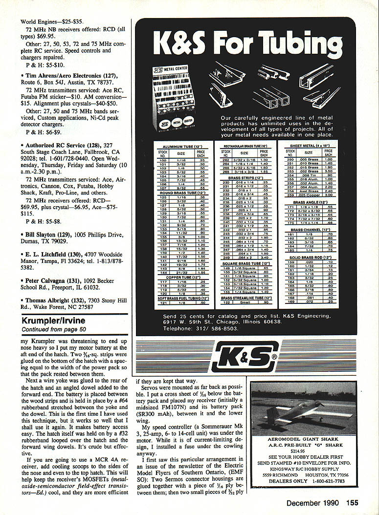
- Nonfunctional interplane struts: made from slightly rounded 3/16 in. balsa inside large plastic drinking straws; they are designed to come out or break before damaging the wing in hard landings.
- Balance the airplane by moving internals where possible rather than adding external ballast.
Weights (original prototype)
- Top wing, complete (uncovered): 46 g
- Balsarite adhesive: 3 g
- Covered: 54 g
- Covered and lettered: 59 g
- Bottom wing: 3 g less than top wing
- Fuselage, complete (dowels, cabane wires, landing gear; no pushrods, wheels or cabane cross wires — uncovered): 78 g
- Balsarite adhesive: 2 g
- Covered: 83 g
- Stabilizer and elevator (uncovered): 8 g; covered: 11 g
- Fin and rudder (uncovered): 4 g; covered: 5 g
- Total airframe: 12 oz.
- Radio weight: 7.5 oz (original); later with MCR‑4A RX: 3.5 oz
- Motor weight with connectors, prop and adapter: 9 oz
- Battery weight with connector (7 × 900SCR): 10.5 oz; with 6 × 1200SCR: 11.5 oz
- Total flying weight with STW and regular radio (7 × 900SCR): 39 oz
- Total flying weight with MCR‑4A radio (6 × 1200SCR): 36 oz
Flying
- The original Krumpler required right rudder and a little up trim. Level flight is maintained at about 1/4–1/3 throttle; quick takeoffs and aerobatics need full (or nearly full) throttle.
- With the landing gear fairly far forward, be ready for swing on takeoff. It takes off in less than 50 ft with no wind and less with a breeze.
- After liftoff, keep it flat to gain speed before applying much elevator. Keep first flights gentle to get a feel for the airplane.
- Rudder authority and elevator are sufficient for figure eights in a small area. Loops need nearly full power or a little dive first, and are best into the wind.
- Spins: move the C/G rearward (I removed a two‑ounce speed controller from the nose to help); with a little power at the top of the stall the Krumpler will spin.
- Stall turns and snap rolls are straightforward; snap rolls from level require a bit of up elevator, then a rapid roll input and back pressure.
- Glide is moderate (biplanes are draggy), and is slightly better without struts.
- Battery notes: SCR cells have a sharp discharge "knee" (like running out of fuel); SC cells give a clearer warning (about 30 seconds) before depletion.
- Best conditions: calm weather or steady breeze. Evening flying is especially enjoyable with the sun shining through the covering.
- Winter: skis were fitted when using the Goldfire motor; flying qualities were slightly affected by extra drag and weight but remained acceptable.
Conclusion
If I built a second Krumpler I might shorten the nose a bit or try straight wings to reduce nose‑heaviness, or otherwise adapt the basic wing for a small scale electric. In the air the Krumpler has a bit of Tiger Moth and a little Bücker Jungmann character. A creative modeler could modify the wing and make a pleasant small scale electric.
If you build a Krumpler, please send comments and a photo to:
Martin Irvine 34 Beaver Crescent Kingston, Ontario, Canada K7M 7C1
I will answer all correspondence but would appreciate your sending a stamp.
Transcribed from original scans by AI. Minor OCR errors may remain.

