
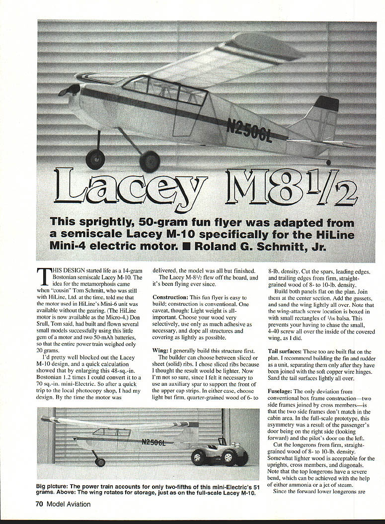
Lacey M8 1/2
This sprightly, 50-gram fun flyer was adapted from a semiscale Lacey M-10 specifically for the HiLine Mini-4 electric motor. Roland G. Schmitt, Jr.
This design started life as a 14-gram Bostonian semiscale Lacey M-10. The idea for the metamorphosis came when "cousin" Tom Schmitt, who was still with HiLine, Ltd. at the time, told me that the motor used in HiLine's Mini-6 unit was available without the gearing. (The HiLine motor is now available as the Micro-4.) Don Srull, Tom said, had built and flown several small models successfully using this little gem of a motor and two 50-mAh batteries, so that the entire power train weighed only 20 grams.
I'd pretty well blocked out the Lacey M-10 design, and a quick calculation showed that by enlarging this 48-sq.-in. Bostonian 1.2 times, I could convert it to a 70-sq.-in. mini-electric. After a quick trip to the local photocopy shop, I had my design. By the time the motor was delivered, the model was all but finished. The Lacey M-8 1/2 flew off the board, and it's been flying ever since.
Construction
This fun flyer is easy to build; construction is conventional. One caveat, though: light weight is all-important. Choose your wood very selectively, use only as much adhesive as necessary, and dope all structures and covering as lightly as possible.
Wing
I generally build this structure first. The builder can choose between sliced ribs or solid (sheet) ribs. I chose sliced ribs because I thought the result would be lighter. Now I'm not so sure, since I felt it necessary to use an auxiliary spar to support the front of the upper cap strips. In either case, choose light but firm, quarter-grained wood of 6- to 8-lb. density. Cut spars, leading edges, and trailing edges from firm, straight-grained wood of 8- to 10-lb. density.
Build both panels flat on the plan. Join at the center section. Add the gussets, and sand the wing lightly all over. Note that the wing-attach screw location is boxed in with small rectangles of 1/16-in. balsa. This prevents having to chase the small 4-40 screw over the inside of the covered wing, as I did.
Tail surfaces
These too are built flat on the plan. I recommend building the fin and rudder as a unit, separating them only after they have been joined using soft copper wire hinges. Sand the tail surfaces lightly all over.
Fuselage
The only deviation from conventional box-frame construction—two side frames joined by cross members—is that the two side frames don't match in the cabin area. In the full-scale prototype, this asymmetry was a result of the passenger's door being on the right side (looking forward) and the pilot's door on the left.
Cut the longerons from firm, straight-grained wood of 8- to 10-lb. density. Somewhat lighter wood is acceptable for the uprights, cross members, and diagonals. Note that the top longerons have a severe bend, which can be achieved with the help of either ammonia or a jet of steam.
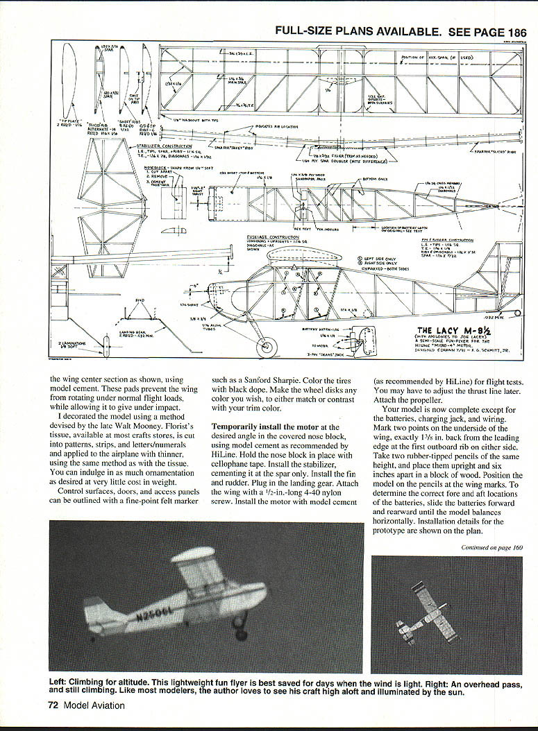
Lay out the side frames on the building board, allowing the nose side pieces to be joined using temporary bulkheads in the nose and another in the rear cabin area to maintain exact alignment and squareness. After installing forward cross members and diagonals and after the adhesive has set, draw the tail posts together and secure with glue. Complete the structure by adding the remaining cross members and diagonals.
It's best to install short lengths of 1/32-in. I.D. aluminum tubing in the landing-gear reinforcing gussets before covering the upper and lower surfaces of the nose. Use 1/32-in. sheet balsa for the frame sides, 1/8-in.-sq. balsa for the top-nose pieces, and 1/8 x 3/4-in. balsa for the bottom nose piece shaped as shown on the plan. Mark the position of the side 1/8-in.-sq. pieces to ensure the correctly aligned support for the nose block in the desired location. Another way to get this right is to use a temporary jig made from scrap balsa.
As the plans show, the top center cross member is 1/16-in. plywood. Drill two holes with a 3/32-in. drill. Place a drop of thin CyA (cyanoacrylate) glue in each hole and allow to harden. Tap the holes 4-40, add a second drop of CyA, and tap again after the CyA has completely hardened.
Landing-gear struts and wheels
Bend the gear as shown from two lengths of .032-in. music wire. Make sure both sides are identical. Bind the wire together where indicated with fine copper wire; use two short pieces of snug-fitting plastic tubing such as heat-shrink tubing over the bindings. Don't make the final 90° bend of the strut until the tubing is joined. Insert the struts into the tubing sockets in the fuselage to obtain correct spacing; tack the wire bindings or tubing in place and drop CyA. Allow to harden, then withdraw the gear from the fuselage.
Laminate the wheels from two disks of 3/8-in. light balsa. Mark the location of the 1/16-in. center hole and drill. Thread a 2-56 machine screw through, secure with washer and nut. Chuck the screw in an electric drill or Dremel tool and shape the balsa disks using a sanding block, emery board, or shaping with fingernails. Remove the screw, glue in a short piece of 1/32-in. I.D. aluminum tubing as the axle bearing. Install wheels on the landing struts, retaining with a 1/16-in.-long piece of tubing secured with CyA.
Bend the tail wheel from .032-in. music wire and fill the center with a small piece of tubing before installation.
Shape the nose block/motor mount from a piece of soft 1/4-in. sheet as shown on the plan. Make sure it fits snugly in the fuselage nose and matches its contour. After shaping, cut the nose block apart as indicated, using a razor blade, and cut out the center. Glue the parts back together, and sand the unit lightly. Trial fit—but don't install—the motor, making certain you've provided clearance for the armature.
Covering and finishing
Lightly sand the entire framework, removing any irregularities or protrusions—defects that would mar your covering. Carefully dope the structure with two coats of Litecoat thinned 50/50, sanding again between coats. Recheck the model for squareness and warps; correct any imperfections that remain.
I used white Japanese tissue on the prototype, attached by applying thinner through the covering. At this point leave three bays on the bottom of the fuselage uncovered from immediately in front of the wing trailing edge aft. Spray the tissue lightly with rubbing alcohol to shrink it. When shrinking the wing covering, wet only one side at a time, and pin the structure to your building board with the trailing edge raised 1/8 in. at the tip to provide washout. The tail surfaces should be pinned down flat to minimize warpage after wetting the covering.
Once you've succeeded in eliminating all wrinkles, give the covering two coats of thinned Litecoat. For the wing panels, I recommend doping one surface at a time, pinning the panel down until the Litecoat has dried. The tail surfaces too should be doped one surface at a time, then pinned down flat to dry.
Lightly sand all surfaces, then repeat this sequence for the second coat. Affix the small, medium-grit sandpaper pads to the top of the fuselage and to the underside of the wing and sand each lightly until all nibs and runbacks are removed and the surfaces are satin-smooth.
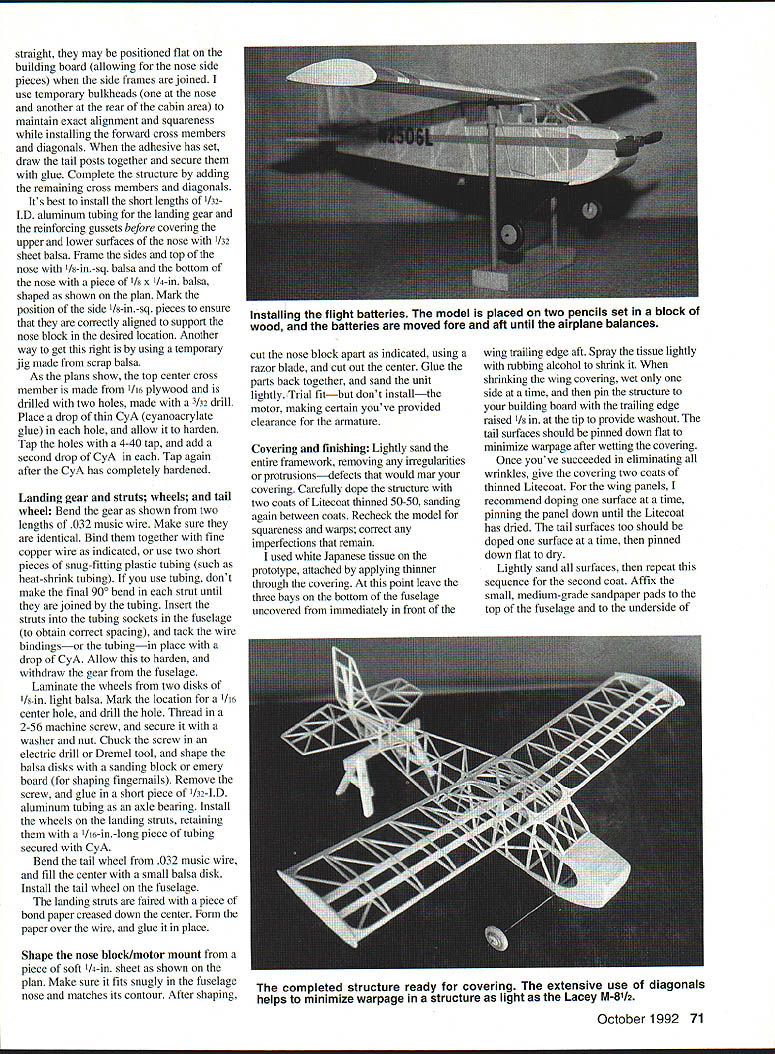
Install the batteries in the nose block with a thin film of sticky tape. Ensure balance by moving the batteries fore and aft until the airplane balances.
Glue thin plywood pads to the wing center section as shown, using model cement. These pads prevent the wing from rotating under normal flight loads, while allowing it to give under impact.
I decorated the model using a method devised by the late Walt Mooney. Florist's tissue, available at most craft stores, is cut into patterns, strips, and letters/numerals and applied to the airplane with thinner, using the same method as with the tissue. You can indulge in as much ornamentation as desired at very little cost in weight.
Control surfaces, doors, and access panels can be outlined with a fine-point felt marker such as a Sanford Sharpie. Color the tires with black dope. Make the wheel disks any color you wish, to either match or contrast with your trim color.
Temporarily install the motor at the desired angle in the covered nose block, using model cement as recommended by HiLine. Hold the nose block in place with cellophane tape. Install the stabilizer, fin, and rudder. Plug in the landing gear. Attach the wing with a 1/2-in.-long 4-40 nylon screw. Install the motor with model cement (as recommended by HiLine) for flight tests. You may have to adjust the thrust line later. Attach the propeller.
Lacey M-8-1/2 Continued from page 72
Note that I used a three-pin Dean's connector rather than the charging jack furnished by HiLine, because other models—and my field connector—use a Dean's plug. It isn't necessary to keep the charger connected after charging. Simply insert a plug that has two pins shorted together to establish circuit continuity. This will start the motor for flight.
Test-flying
Select a calm day and an area covered with the proverbial tall grass. Remove the prop, and glide the model into the wind with a gentle but firm launch. Make any necessary adjustments in the glide path by shimming the leading edge of the stabilizer up or down as appropriate.
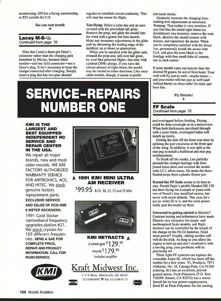
When you're satisfied with the glide path, reinstall the prop and, still over tall grass, try your first powered flight—but only with a partial (30%) charge. If you have the correct amount of right thrust, the model may be circled in either direction. Like most cabin models, though, it seems to prefer left-hand circles.
Gradually increase the charging time, making trim adjustments as necessary. Warning: that rudder is very sensitive. If you find that the initial right thrust (or downthrust) was incorrect, remove the nose block, dissolve the model cement with thinner, and reposition the motor. When you're completely satisfied with the thrust line, permanently install the motor with CyA, and glue the nose block to the fuselage with four small dabs of cement, one in each corner.
If your model came out heavier than the desired 50 grams, do not lose heart. Your craft will fly just as well—maybe better—and your motor will run just as well (and without harm) on three cells! So relax and have fun.
Fly Electric!
Transcribed from original scans by AI. Minor OCR errors may remain.

