
Laird Solution
There you are, just minding your own business reading an interesting book on air racing. Then—bam!—they do it to you. Suddenly you've fallen prey to an irresistible urge to create a scale model of whatever captivating airplane has just leapt off the page and into your heart.
I was innocently reading Robert Hull's September Champions when I lost my head. The Laird Solution had always been a favorite of mine—and there it was, the full‑size aircraft in all its beauty on page 33. The caption infected me: the Solution had been built in less than a month, just in the nick of time for the 1930 Thompson Trophy Race.
It was kismet. How's a modeler to resist? I repaired to the workshop, checked the balsa rack, mined a set of three‑view drawings from the pile of books, and made sure everything else I needed was there. The balsa yielded to knife and sander, and in just a short weekend the metamorphosis was complete. The model in the photo from Hull's book was ready to take to the air.
Modeling is addictive. I am haunted by visions of Golden Age air racers streaking past—two, three, maybe four in the same circle—bright colors dazzling the eyes as roaring engines tear at the air. That little biplane that Speed Holman rolled onto the flying field in 1930 had been on my list for quite some time.
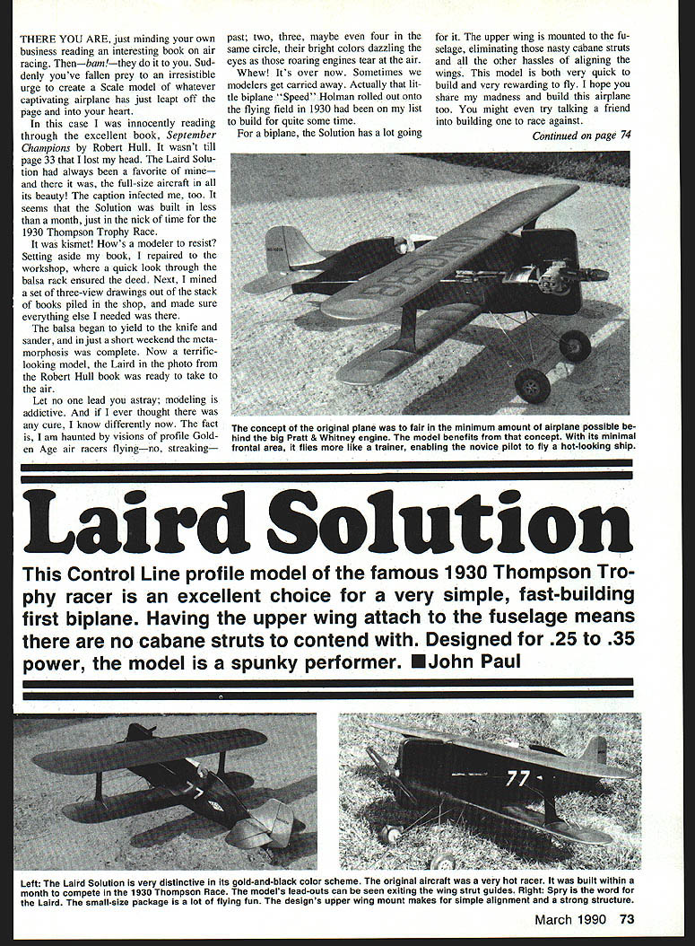
For a biplane, the Solution has a lot going for it. Having the upper wing mounted to the fuselage eliminates cabane struts and the hassles of aligning them. This model is very quick to build and very rewarding to fly. I hope you share my madness and build this airplane too. You might even talk a friend into building one to race against.
Overview
This control‑line profile model of the famous 1930 Thompson Trophy racer is an excellent choice for a very simple, fast‑building first biplane. With the upper wing attached to the fuselage there are no cabane struts to contend with. Designed for .25 to .35 cu in engines, the model is a spunky performer.
- Power: .25–.35 cu in engine
- Style: Control‑line profile biplane
- Notable: Upper wing mounts directly to fuselage; simplified biplane assembly
Construction
Wings
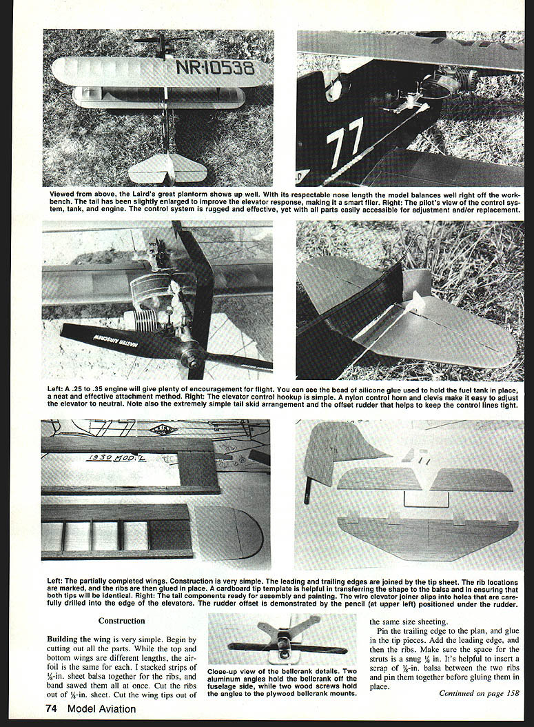
Building the wings is simple. Begin by cutting out all parts. While the top and bottom wings are different lengths, the airfoil is the same for each.
- Stack strips of 1/8‑in. sheet balsa and band‑saw ribs all at once.
- Cut the ribs and wing tips from 1/8‑in. sheet.
- Pin the trailing edge to the plan and glue in the tip pieces.
- Add the leading edge, then glue in the ribs. Make sure the space for the strut is a snug 1/8 in.
- It helps to insert a 1/8‑in. scrap between two ribs and pin them together before gluing.
- When the glue is dry, remove the wing from the plan and trim the tips to shape.
- Make a light cardboard outline template, then mark, carve, and trim the leading edge to shape with a razor plane.
- Sand the leading edge and tips. Add a 1/32‑oz. weight to the top outboard wing tip.
Assemble the second wing the same way.
Tail
- Cut out stabilizer, elevator, fin, and rudder from sheet balsa.
- Sand all edges to a fair shape.
- Join the elevators with a wire as shown on the plans and hinge them to the stabilizer.
- Sig's Easy Hinges are recommended—insert the hinge and glue the slots.
- Cement the rudder to the fin with a 1/16‑in. offset and set aside.
Fuselage
Make the fuselage core from a single sheet of 3/16‑in. balsa. Pick a sheet that's lightweight and straight; splice sheets if necessary to make a sheet about 6 in. wide, or to match the required fuselage length.
- Transfer the fuselage outline to the sheet and cut out the core.
- Note all cutouts in the core: engine mounts, landing‑gear block, upper and lower wing slots, bellcrank, and stabilizer. Cutting these now speeds and improves assembly accuracy.
- Cut plywood doublers, engine mounts, and landing‑gear block.
- Lay the first plywood doubler on the bench, apply white glue, and set the fuselage core over it.
- Position engine mounts and landing‑gear block, add glue, and lay the top plywood doubler in place.
- Add blind mounting nuts for the engine and glue the 3/8‑in. sheet cowl block on top.
- After checking alignment, weight the entire sandwich and allow glue to cure.
Make the core nose block and shape it to the outline shown on the plans.
Control System
Use a simple bellcrank arrangement as shown on the plans.
- Two aluminum angle brackets hold the bellcrank off the fuselage side, secured with two wood screws.
- Plywood bellcrank mounts are glued to the same‑size sheeting.
- Mount the fuel tank in the forward fuselage and secure it with a bead of silicone glue or rubber straps.
- The firewall and engine mount should be rigid and allow easy engine removal.
Fitting and Assembly
The wings can be covered and finished while the fuselage dries. The prototype received five coats of dope with light sanding between coats.
- Bend landing‑gear parts from silver wire but do not solder until installed.
- Make up the bellcrank assembly; it's simply standard with the addition of the two aluminum angles.
- When glue has cured, trim the fuselage and drill holes for landing‑gear struts and J‑bolts.
- Install landing‑gear struts, bind tightly with copper wire and then solder.
- Glue small plywood bellcrank mounts and install the bellcrank.
- Add lead‑outs now—they are hard to install after wings are attached.
- Fit stabilizer and rudder, glue in place and ensure proper alignment.
- Install the elevator horn and hook up the pushrod. Test for smooth operation and enlarge fuselage slot if necessary.
- Round off fuselage corners to taste.
Cut out plywood struts and drill holes for lead‑outs in at least one strut. Trim away covering from slots on top of the bottom wing and bottom of the top wing. Check strut and wing fit; make the notches fit nicely if necessary.
Mix one‑hour epoxy and glue the bottom wing to the fuselage. Pin the wing in place and epoxy in the struts. Add epoxy to the tops of the struts and to the fuselage where the top wing will be glued. Slip on the top wing, position it, and measure the gap between the wings to ensure they are parallel. Adjust as necessary; using slower‑setting epoxy gives time for final alignment. Allow to cure.
Covering and Finishing
Apply a few coats of dope, sanding lightly between coats, to the fuselage and tail assembly. The full‑size Laird Solution was painted black and gold, and the model duplicates that scheme:
- Wings, rudder, fin, stabilizer, and elevator: gold
- Fuselage and landing gear: gloss black
Just before the race the full‑size plane had racing number 77 painted in white. For the model, registration letters and numbers were cut from a black trim sheet and applied to the fuselage.
Flying
- Bolt on your favorite engine in the .25–.35 size range.
- Add wheels and finish the lead‑outs.
- Check the balance point shown on the plan.
The nose length is respectable and the model should balance well right off the workbench. The tail has been slightly enlarged to improve elevator response, making this a forgiving flier for novice pilots yet a lively ship for more experienced flyers.
Get to the field early so pre‑race fever can subside. Then crank up the engine and fly for the past!
The Laird Solution is a spunky model with lots of life. If you want to try inverted racing, modifying the wing airfoil to a symmetrical section would be fairly easy. Hmmm... maybe I should try skyracers.
Transcribed from original scans by AI. Minor OCR errors may remain.

