
Lanzo's RC-1
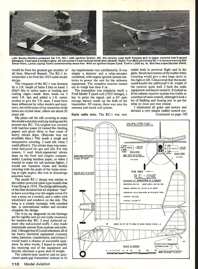
When Chet Lanzo was 20, more than half a century ago, he created a remarkably simple, functional, and graceful gasoline-powered model with superb flying ability. It was a contemporary of the famed Bassett designs and the KG (Kovel-Grant) published in the 1930s and drew inspiration from those cabin-type models. His objective was radio-controlled flight, as the name RC-1 testifies.
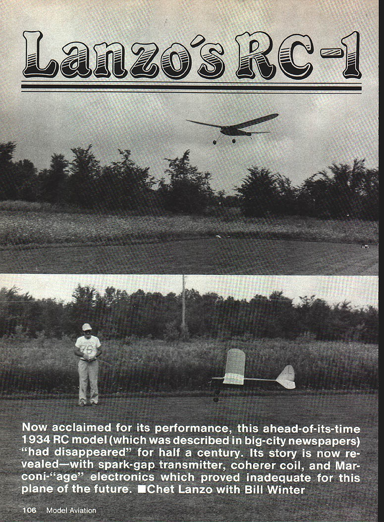
Sometime around 1934, a story about Chet and his craft appeared in the Cleveland Press with an excellent photo of the plane and its creator. The paper leaded: "A high-wing cabin monoplane with a 7-ft spread, powered by a gasoline engine, capable of 50 mph, and equipped with radio controls so that it may be operated from the ground, is the ambitious model airplane project developed by Chester Lanzo for the Junior Aviator National Air Races." The article noted Chet had been interested in models for 10 years, had flown two large models, had learned in craft shops of an East End neighborhood house, and graduated from East Technical High School where he studied aeronautical engineering.
Although self-effacing and humble, Chet's peers consider him one of the finest modelers; his achievements are substantial. The RC-1 story that follows is organized from Chet's own account. My questions have been omitted to give Chet maximum space.
The RC-1 was approved by the Society of Antique Modelers (SAM) in 1982 to compete in its basic contest events; the authenticated design was listed in SAM Speaks as an accepted Antique.
Chet Lanzo's account (summary)
In 1934 I put together the RC-1 as my first attempt at radio-controlling a gasoline-engine-powered model airplane. My goal was to get a motor to operate the gas model, get it into the air to a good height, have a reasonable flight, and then return the model to the vicinity of the launching site—all by radio control. It sounded simple enough, but it proved to be a substantial goal and not easily attained.
I competed in the rubber-powered events at the Nationals held in Akron, OH, in 1934. A new ruling kept gas-powered models from competing against rubber-powered ones in events such as Moffett and Mulvihill. The Texaco event winner was the gas-powered model that made the longest flight, with a new rule limiting fuel to 1/4 oz per pound of model weight.
Maxwell Bassett of Philadelphia, the 1933 winner, retained his title with a flight of 21 minutes, 57 seconds. Several large gas-powered models flew in that meet; a few, unable to climb high enough to clear the 12-story Goodyear dirigible air dock, flew into the building with engines running and slid down its sides. I thought it would be a great idea to build a gas model and prevent these fly-aways by controlling it with radio.
Our Cleveland club was intrigued with the Brown Jr. .60 engine, which was just becoming available. Funds from sale of small scale models built by club members allowed purchase of one Brown Jr. We agreed each club member could use it for a short period. I designed and built the RC-1, a 7-ft-span cabin model, and waited my turn to use the engine.
The Brown Jr. became available in fall 1934, and flying tests proved the RC-1 to be a very capable airframe. It climbed steadily under power and had a stable, slow glide. I planned to trim the model and work out bugs before installing the radio. I had built models for ten years—mostly rubber-powered free flight, scale free flight, and contest types (what we would now call Wakefield). The RC-1 provided a good opportunity to learn what was needed to produce a controllable RC gas model.
Radio control (RC) was in its infancy. There were some heavy radio systems used to control model boats and light planes during WW I and a few isolated experimenters, but no miniature components or lightweight units were available. Parts were heavy, and lightweight batteries did not exist; receivers used filament, high-voltage plate, and bias batteries and heavy tubes.
Beginnings of the model design
The design stems from the full-size cabin airplanes of the day and was especially influenced by Maxwell Bassett's 1933 cabin model. The RC-1 uses many features of those cabin designs.
- Wingspan: dictated by a 3-ft length of balsa I had on hand. Rather than splice spars or leading/trailing edges (which I felt made them weak), I used 3-ft tips and added a 1-ft center section to give the 7-ft span.
- Outline: simple rectangular wing with rounded tips, conventional rudder and elevator, cabin with windshield and side windows, and an engine cowling (a fashion of the time).
- Structure: stick-type construction with 1/4-in.-sq. diagonals in the fuselage for rigidity (not strictly necessary for modern RC).
- Covering: original covered with bamboo paper (similar to blotting paper) with 3–4 coats of heavy nitrate dope (butyrate was not available then). When lighter tails were desired I used doubled Japanese tissue with grains crossed at right angles to discourage puncture tears. Silk was used when affordable; silk with dope is recommended for present-day RC restorations.
- Fuel/engine considerations: nitrate dope was somewhat fuel-proof; black-pigmented nitrate dope was used on the engine compartment.
I used Ambroid cement and even homemade cement made from acetone and celluloid. My thinking was to eliminate heavy electrical equipment (vacuum tubes, batteries, transformers, relays) to reduce weight on the airborne equipment.
Radio choice and installation
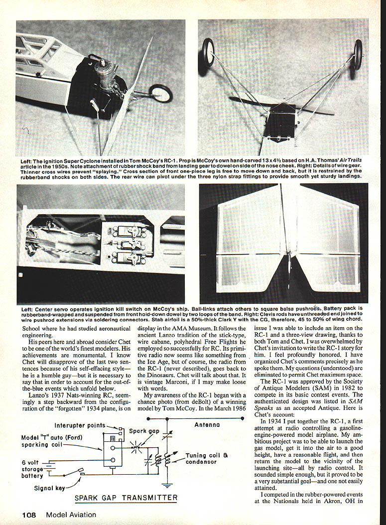
The coherer-type receiver with its associated spark-gap transmitter seemed to fit weight requirements. It was essentially a detector and a relay-actuator combined, using engine ignition system batteries for airborne power. The complete receiver weighed less than 8 oz.
The transmitter was very simple: a Ford Model T spark coil (1923 vintage), a key to pulse the signal, and a 6V auto storage battery, plus antenna and tuned coil system.
Early radio tests
The RC-1 proved very stable in powered flight and in the glide. Small rudder movements during trimming produced large, predictable circles. The model handled the additional 1/2 lb weight of the receiver quite well.
The coherer receiver was bench-tested and seemed viable, although it took a lot of fiddling to get the relay to close and stay closed. I eliminated gears and motors and devised a very simple electric control system.
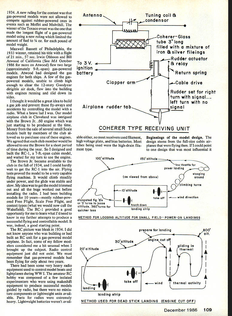
The receiver operated only when the engine was running and producing the vibration necessary to decohere the coherer. The coherer was mounted on the engine firewall. When the key was released (no signal), vibration from the Brown Jr. engine would decohere the receiver and break the actuator circuit; this cleared the system and made it ready to receive the next signal. A heavier mechanical device, like a doorbell ringer, could have been used but was rejected because of the weight.
The rudder actuator system I used was not typical of later gear, but it proved workable for the time. I later built larger models (12-ft span, then 9-ft span) to continue development. None of the equipment in the AMA Museum model is similar to the RC-1 receiver; I am collecting old tubes and RC equipment to build a duplicate receiver and transmitter for the museum piece.
Construction notes
All construction techniques on the contemporary plan are suitable for the free-flight version. For radio control—where the model may see heavier stunt loads on the wings—I recommend beefing up the spars:
- Add 1/8 x 1/4-in. spruce spars to the existing spars for increased strength.
- Wing: simple rectangular with polyhedral; reinforce spars around the landing gear area.
- Fuselage: conventional stick construction; it looks flimsy but is very strong for its weight and appropriate for Old-Timer stick-and-paper airplanes.
Tow-launching:
- The RC-1 can be successfully towed to about 1,000 ft using a standard tow winch and towline (same as modern sailplane models).
- Attach the tow hook under the belly; use a 1/8-in.-thick plywood insert inside the body longerons and crosspieces.
- The tow hook may be a simple bent-screw hook. Install 1/4-in.-sq. hardwood reinforcing crosspieces for the hook inside the fuselage.
- Position the hook about 1-1/2 in. forward of the center of gravity (CG).
- If the towline has a parachute attached, remove it or make it inoperative to prevent entanglement with the landing gear.
- Use small, short pulses on the winch power switch during initial tows. Watch for wrinkling of the covering near the dihedral joint, which indicates over-stressing of the wing; let up on the winch if this appears.
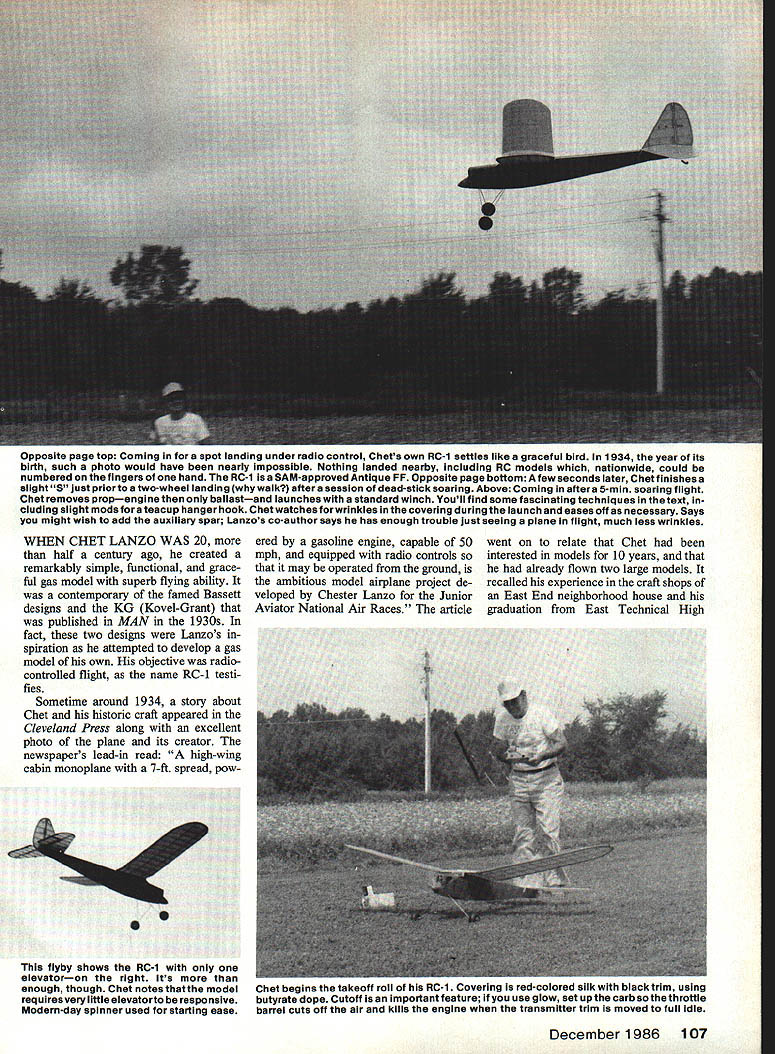
I recommend adding 1/8 x 1/4-in. spruce reinforcing spars if you intend to do any winch-launching. Remove the prop and place a spinner on the shaft for safety during towing. I have made towed flights of five minutes in good weather.
Setting up for flying: the CG should be about one-third of the wing chord from the leading edge. For sport flying, the CG can be moved forward to the 33% position for added stability. The more aft position reduces sinking speed but sacrifices some longitudinal stability.
Setting up the RC-1 for flying
- Engine break-in: run the engine on the bench for a good half hour until it will start with a couple of prop flips. Work out bugs before installation.
- Check CG: ensure it matches plan position; move forward for beginner-friendly stability.
- First test flight: choose a sunny, warm day with no wind or only a light steady breeze. Late afternoon is often ideal.
- Taxiing: adjust the engine to a very low idle that moves the model slowly over grass. Taxi for two tanks of gas to get a feel for controls.
- Takeoff: place the model in the takeoff area facing into the wind, apply one-eighth to one-quarter throttle. It should taxi about 20 ft and become airborne.
- Climb and cruise: the RC-1 should climb slowly and steadily at one-quarter throttle and fly straight and level with all controls neutral and minimal throttle. With the large elevator area the RC-1 is almost impossible to stall in the glide or under low power.
- Landing (power-off): bring the model in over the landing strip downwind at about 20 ft, cut the throttle, and glide in using 50–100 ft of strip. Just before touchdown, give a tap of up elevator for a three-point, semi-stalled landing.
- Power-on landings: possible with small down trim in the elevator. At full throttle the model becomes very active and fast; at full throttle the RC-1 will hop off in 5–10 ft and climb near-vertically.
Climb performance: with a glow .45 or a Super Cyclone .60 the RC-1 can perform near-vertical climbs; with long engine runs it can climb almost out of sight.
Soaring, thermals, and safety maneuvers
- Never glide downwind; you'll drift farther and risk losing the model. Glide upwind so the model will drift back to you.
- Getting down from a powerful thermal: without flaps/spoilers, use a stalled-spin descent.
- Apply plenty of up-elevator (about 15°).
- Pull back full stick for full up-elevator.
- Two seconds later, apply full left rudder to enter a tight left spin.
- Hold the controls—the spin will bleed off altitude without excessive speed.
- Avoid diving out of thermals; high-speed dives can cause wing/tail shredding, flutter, or structural failure.
- If the model disappears in cloud, a stalled turn/spin often brings it back into view.
- Finding thermals while gliding: imagine a large hot-air-balloon-sized thermal column. Fly straight hands-off; if the model starts to rise, you're in the thermal. If it begins to change course, turn back into the thermal until you penetrate it, then circle in 50-ft turns with a little up trim to climb.
Soaring in the glide is personally very satisfying—silent flight and searching thermals is an enjoyable part of RC flying.
Flight envelope and contest suitability
The RC-1, as constructed, is a slow-flying, predictable sport-type model. It has been flown in Old-Timer competitions and is suited for Texaco and Antique classes in SAM events and does well in limited-engine-run classes. It is not a pattern model but is competitive and fun in club fun-fly events.
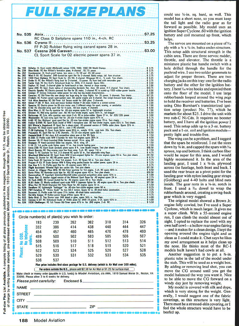
Since Chet has about 800 plans of the RC-1 and there is interest arising from its discovery, the magazine service will not supply plans; full-size detailed plans are available for $8.00 postpaid from:
Chet Lanzo 1485 Lester Rd. Valley City, OH 44280
Tom McCoy's mods to the RC-1
Tom McCoy developed changes to suit high-performance SAM/FF-RC assist flying. His modifications are significant to sport RC fliers who may perform simple aerobatics or tow-launching. Following is a summary from McCoy:
- Controls and stab:
- The RC-1 was originally rudder-only free flight; McCoy hinged the stab with a second spar at the elevator/stab break (leading edge of the elevator).
- The elevator is very large and must be moved in a small arc. McCoy uses dual rates; if you don't have dual rates, keep elevator deflection to no more than 1/2 in up or down.
- Pushrod: 1/16-in. sq. with carbon-fiber reinforcement; 1/4-in. sq. hardwood could also be used.
- Weight and installation:
- The model has a short nose; keep the tail light and position radio gear as far forward as possible.
- McCoy uses an ignition Super Cyclone .60 with ignition battery and coil mounted up front to help balance.
- Servo and mounting:
- Three servos: rudder, throttle, and elevator, mounted on 1/8-in. ply with a 1/4 x 1/4-in. balsa under-structure to strengthen the cabin area.
- Throttle uses a miniature plastic bat-handle switch with a hole drilled for the pushrod wire; solder grommets are used to adjust travel.
- Two charging jacks on the tray: one for the radio battery, one for the ignition battery.
- Receivers and batteries are held by bent 1/16-in. wire hooks epoxied to the floor and large rubber bands looped around wing pegs.
- Ignition:
- McCoy uses Otto Brunhart's transistorized ignition (product No. 77) driven by two sub-C Ni-Cd cells; no booster battery required. This setup is about a 3-oz battery pack plus a 1-oz coil and ignition module—light and reliable.
- Wing and landing gear:
- Spar reinforcement: cut sizes down 1/8 in and cap spars with 1/16-in. spruce top and bottom; carbon fiber recommended.
- Use 1 x 1/8-in. spruce across the fuselage front and back in the landing gear area. Rear brace used as a pivot point for landing gear with nylon landing gear straps and 4-40 bolts and blind nuts.
- Gear rests in a V-notch in the front. A 7/16-in. dowel wrapped with rubber bands creates a rugged swing-back gear.
- Cowl and balance:
- McCoy uses a half cowl (hollow rear engine fairing) to clean up the nose appearance. Chet liked this arrangement.
- For CG adjustment, use a 3/8-in. plastic tube in the tail as a removable weight box for lead shot; this allows easy CG changes.
- Covering:
- McCoy's model is covered with silk and dope, which is strong for the weight. He recommends fabric coverings; they keep the structure light while providing a stressed-skin effect. If a non-stressed covering is used, the structure must be beefed up.
McCoy notes that the large elevator can make the model a handful under a power climb unless elevator travel is limited or dual rates are used. His mods focus on strengthening the wing and fuselage areas and improving balance and reliability for RC operation.
Final notes
- Construction techniques shown on the plans are fine for free-flight versions; for radio control and winch-launching, strengthen spars and critical areas.
- The RC-1 is gentle under low throttle and predictable in the glide; at full throttle it becomes fast and active.
- Practice the stalled-spin descent and thermal-finding techniques in non-thermal conditions before you need them.
For full-size plans and more information, contact Chet Lanzo at the address above.
Transcribed from original scans by AI. Minor OCR errors may remain.

