
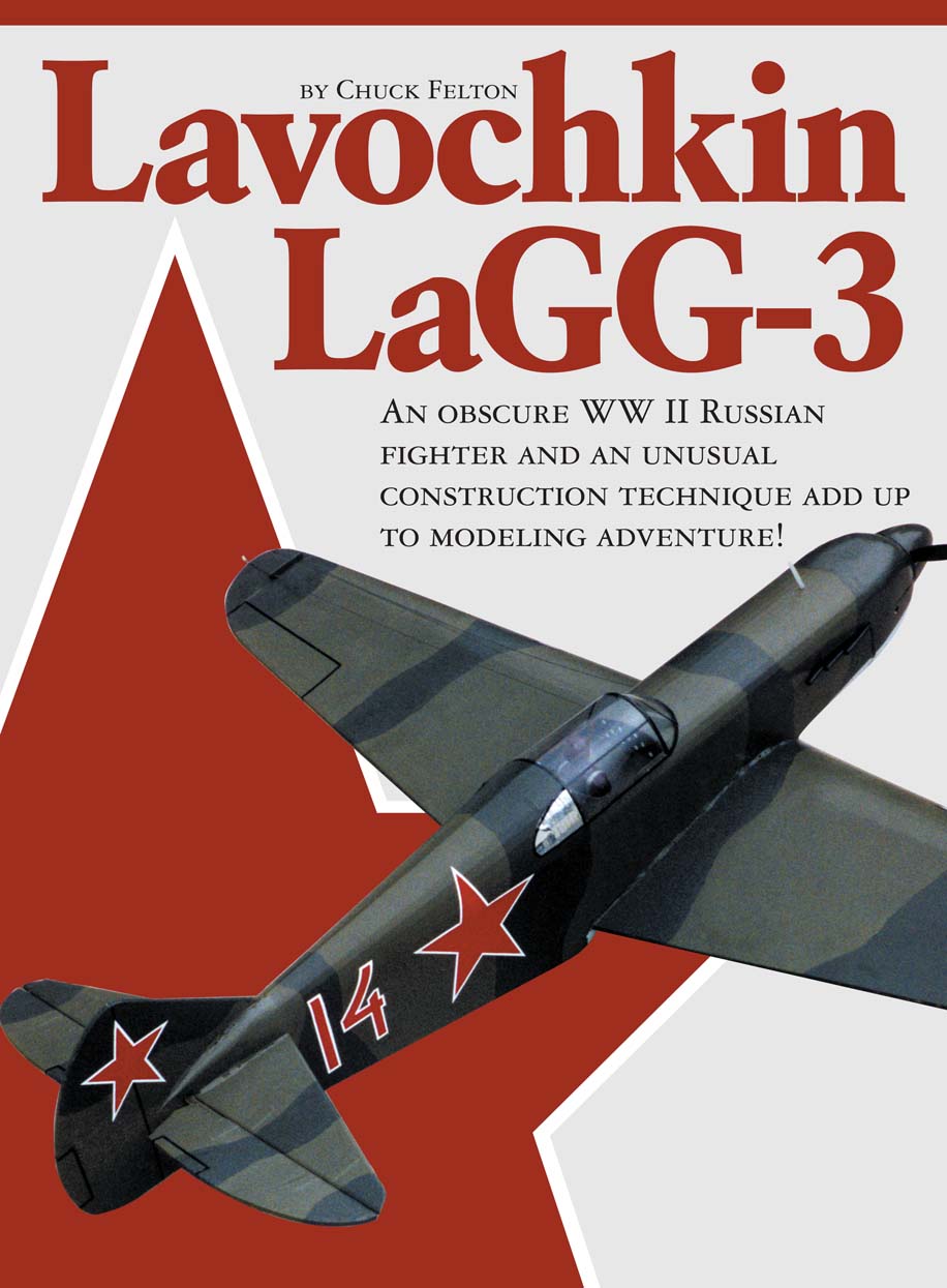
Lavochkin LaGG-3
By Chuck Felton
An obscure WWII Russian fighter and an unusual construction technique add up to modeling adventure!
The LaGG-3 was one of a trio of modern aircraft that the Soviets produced before and during World War II to replace their obsolete fighters. S.A. Lavochkin, V.P. Gorbunov, and M.I. Gudkov designed the aircraft, hence the name LaGG—from their initials.
Although outwardly conventional, the LaGG-3 was the only one of the world's new crop of streamlined monoplane fighters not to have metal stressed-skin construction. Since the Soviet Union faced difficulties at that time obtaining aluminum and other light alloys, the fighter was built mostly from birch plywood and pine.
A new technology called "delta wood" was developed, which consisted of layers of birch strips that were glued cross-grained, impregnated, and used in conjunction with a Bakelite plywood. The result was a neat, clean, maneuverable fighter that showed outstanding robustness and resistance to battle damage. On the other hand, it was inferior to other Russian fighters in all-around performance.
The first of these fighters reached the aviation regiments just a few months before the German invasion. More than 6,500 aircraft had been produced when production ended in September 1943.
My model of the LaGG-3 is inexpensive and simple in construction; I use 1/8-inch corrugated cardboard as the primary building material, which greatly reduces building time and cost.
The design makes use of cardboard's unique features: it can be used in large sections and folded. The wing is built from two big pieces of cardboard, with cardboard ribs and a single spar. The tail surfaces and fuselage are primarily cardboard, with little internal bracing required. The result is a model with a good scale-like appearance that can take plenty of punishment at the flying field.
Cardboard varies in weight, but any 1/8-inch corrugated will do. Sources for this material include box manufacturers and local shopping centers where you can find stacks of discarded boxes. Look for cardboard with brown paper on one side and a white finished paper on the other side. Having the white paper on the outside of the model results in a smoother finish and a neater appearance. The method of folding the cardboard and using gummed paper tape to seal the joints and exposed corrugations is explained in the construction tips.
The model has a wingspan of 65 inches and a length of 58 inches. The bottom of the airfoil is flat with a curved upper surface because of the scoring and folding technique employed. Engines of .40 to .50 displacement can be used. The LaGG-3's size and stability make it a good sport-flying model.
Special Tips for Working With Cardboard
- Gluing: Use water-based glue such as white glue or Titebond. Do not use contact cement since parts cannot be shifted when you are gluing surfaces.
- Folding: Score the fold lines with a screening tool, available at hardware stores. It has a handle with a 1 1/2-inch-radius wheel that you run along a metal straightedge on the fold line.
- Waterproofing: Making cardboard waterproof is simple, and you can do it to the raw material before you cut out the model's parts. Mix 25% clear polyurethane with 75% paint thinner (inexpensive hardware-store variety is fine). Brush the mixture liberally onto the cardboard sheet and allow it to dry for 48 hours. This adds no appreciable weight to the material and renders the cardboard completely waterproof. When you cut the treated cardboard you will find that it is as crisp as wood and cuts sharply and cleanly.
- Finishing: Cardboard provides a solid surface with no open areas to cover and is nonporous. The easiest finishing method is to apply two coats of clear dope, sand lightly between coats with 400-grit paper, and follow with three coats of colored dope. A wide variety of finishing materials such as Solarfilm, MonoKote, and vinyl paper can also be used on the cardboard. With these coverings, do not dope the cardboard's surface; it will result in a better bond.
- Covering the Edges: Cover all seams, joints, and exposed edges with strips of gummed paper tape. Obtain a 1-inch-wide roll from a stationery store. Cut a thin strip to length, dip it in water, and smooth it over the seam(s).
CONSTRUCTION
Cut out all cardboard and wood parts, making sure to note the direction of the corrugations. Score and fold cardboard parts as indicated on the plans.
Empennage
- The fin, rudder, stabilizer, and elevator are each made from two pieces of 1/8-inch cardboard laminated together cross-grain to give 1/4-inch-thick components.
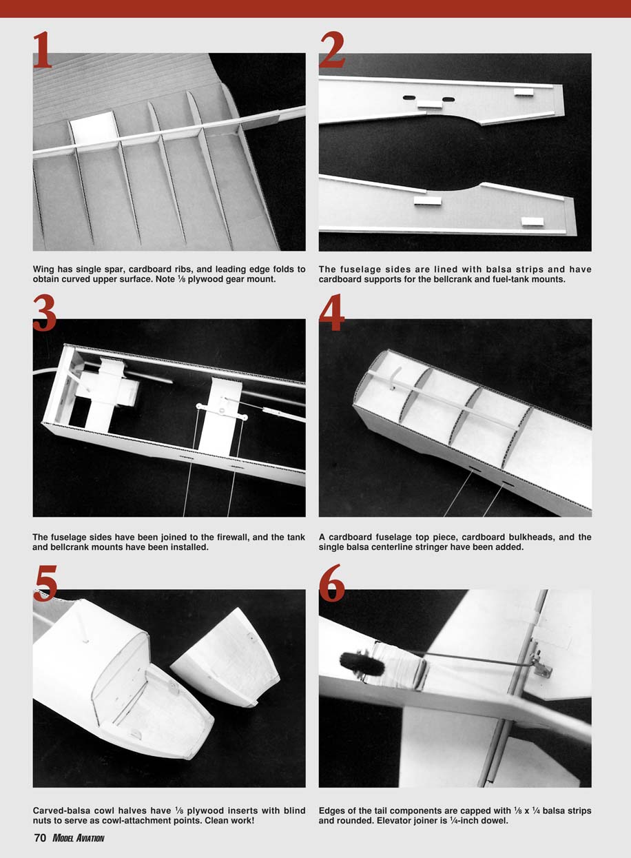
- Edges of the tail components are capped with 1/8 x 1/4-inch balsa strips and rounded.
- Elevator joiner is a 1/4-inch dowel.
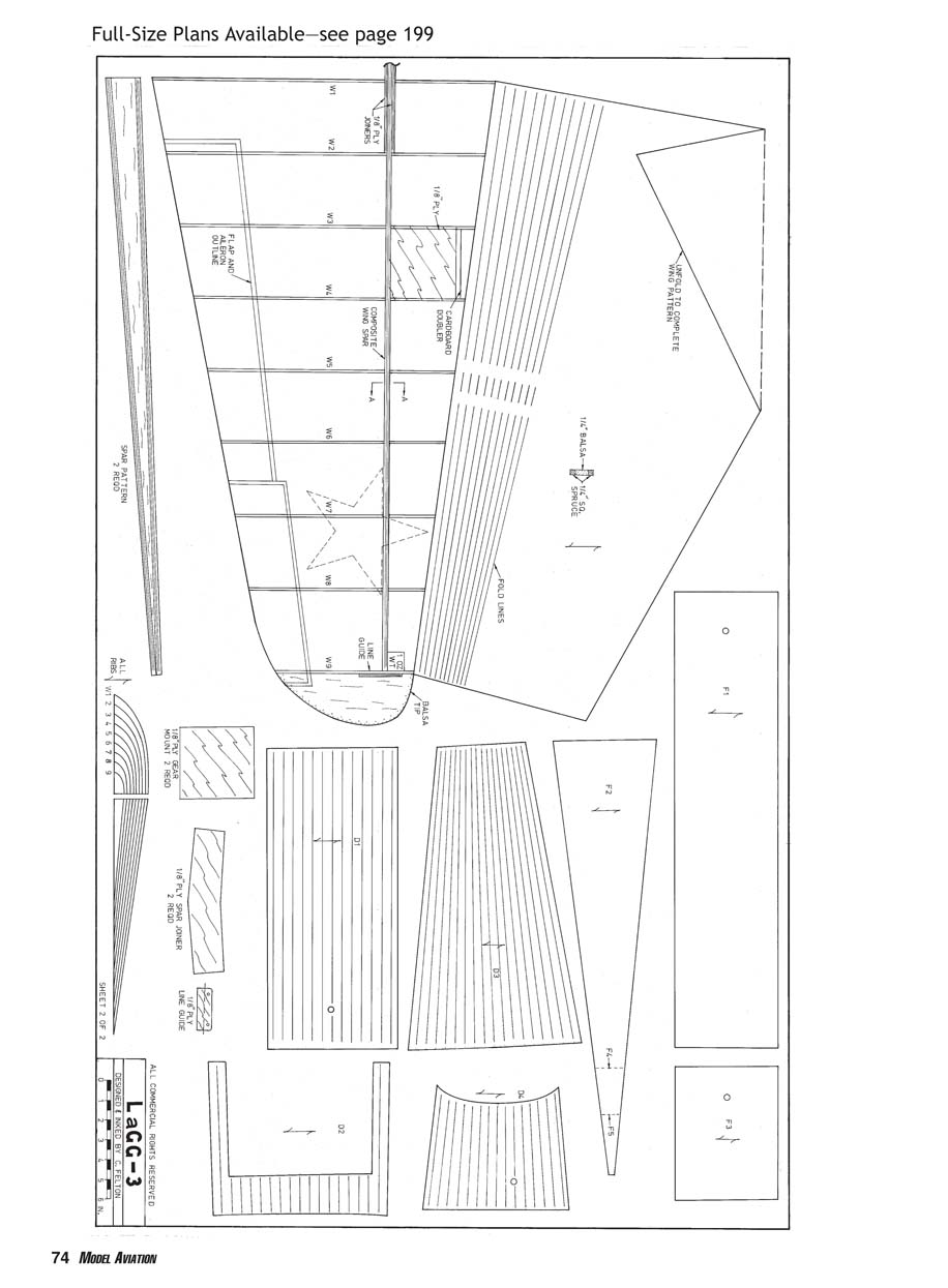
Wing
- Make the wing spar by capping each 1/4-inch balsa spar with a 1/4 x 1/4-inch spruce strip top and bottom. Join the spar halves with 1/8-inch plywood joiners front and rear at the centerline.
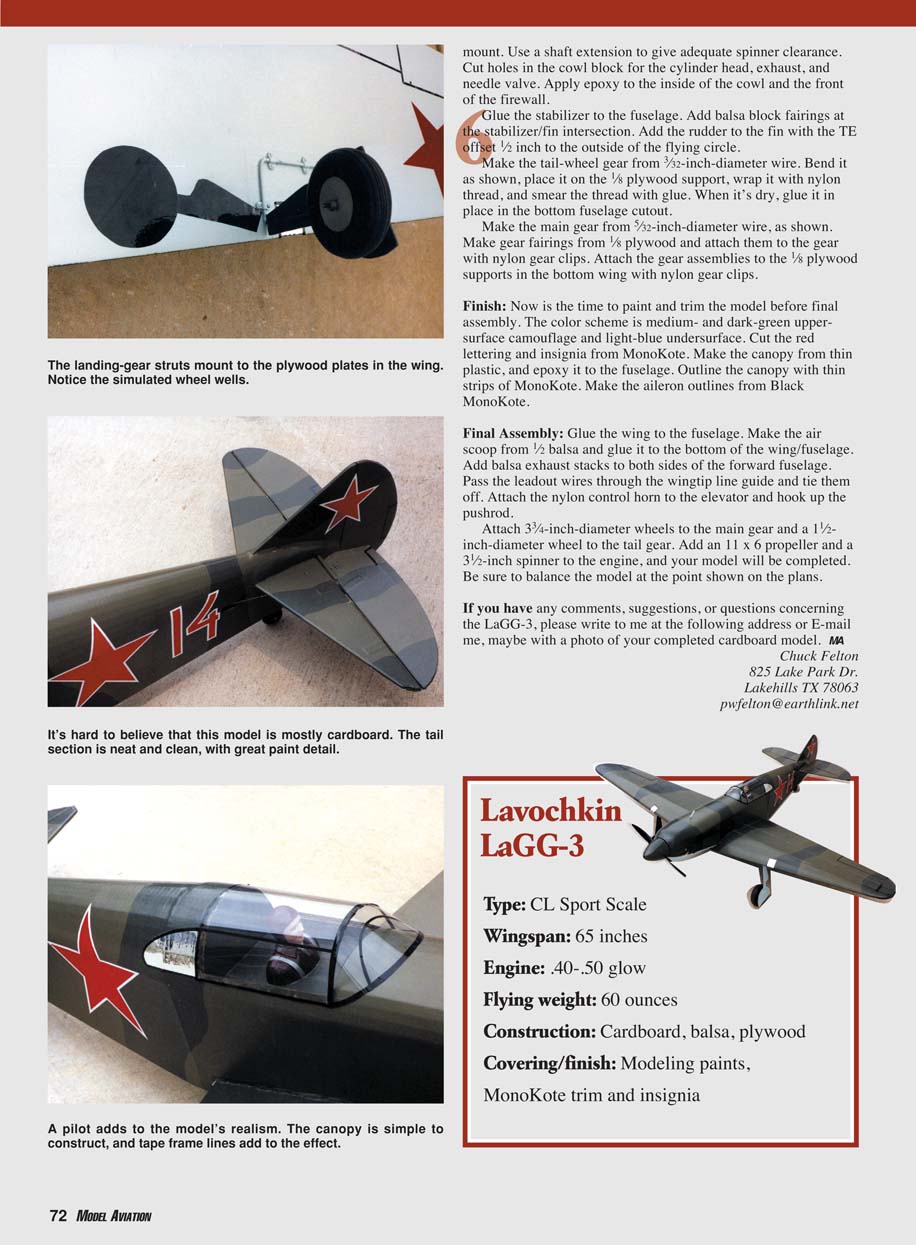
- Glue the 1/8-inch plywood gear mount into the bottom of each wing panel.
- Glue the right side of the wing spar onto the right-hand wing panel. Glue all cardboard ribs into the right wing. Add a cardboard doubler over the plywood gear mount between ribs W3 and W4. Glue a 1-ounce weight to the right wingtip.
- Glue the left wing panel to the left spar in a similar fashion. Add the ribs and gear doubler to the left wing.
- Apply glue to the top of the wing spar, the top of the ribs, and the wing TE. Fold the top wing surface down and pin it securely in place until dry.
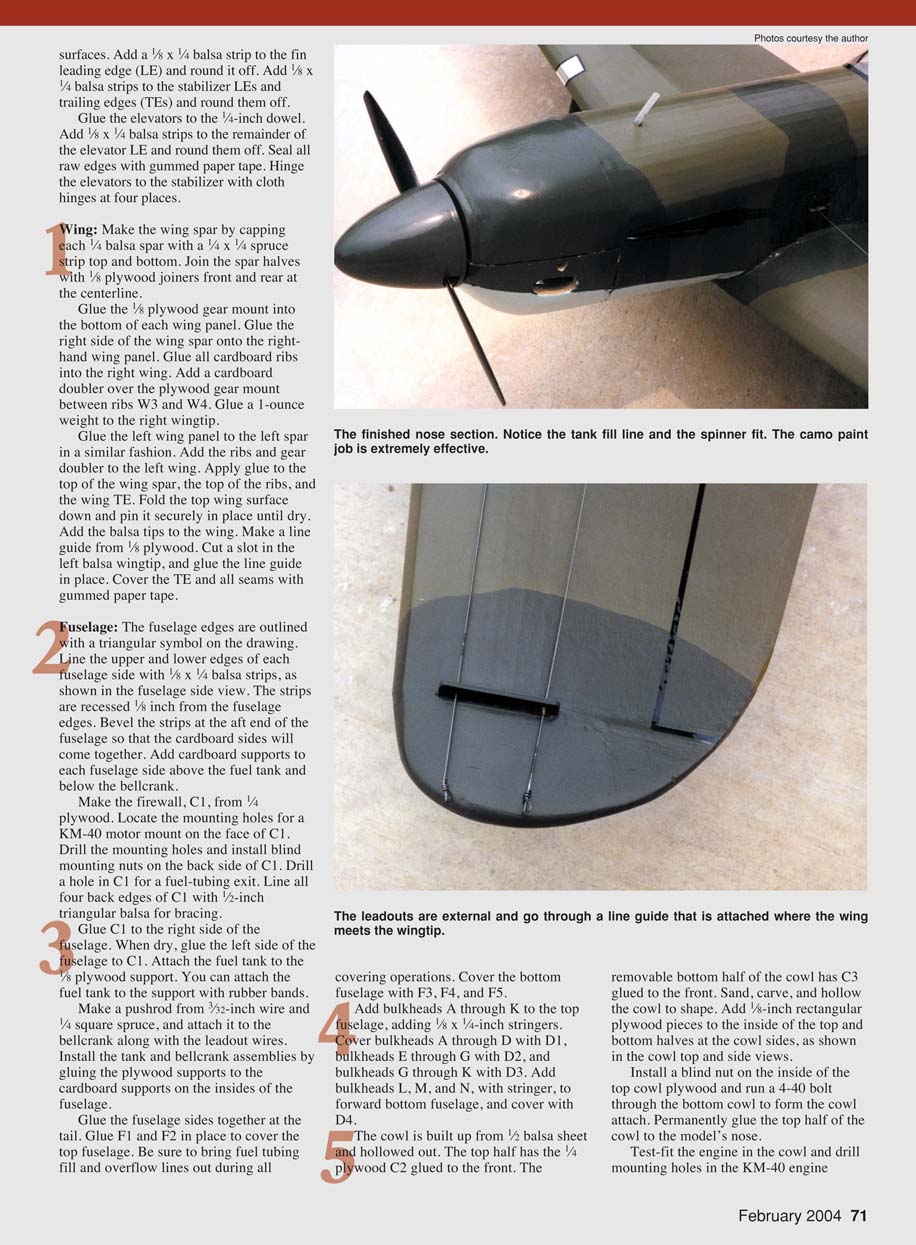
- Add the balsa tips to the wing. Make a line guide from 1/8-inch plywood. Cut a slot in the left balsa wingtip and glue the line guide in place.
- Cover the trailing edge and all seams with gummed paper tape.
Note: The wing has a single spar, cardboard ribs, and leading-edge folds to obtain a curved upper surface. A 1/8-inch plywood gear mount is used.
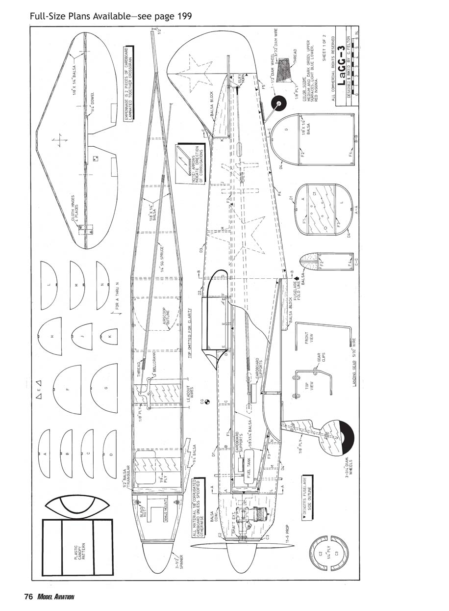
Fuselage
- The fuselage edges are outlined with a triangular symbol on the drawing. Line the upper and lower edges of each fuselage side with 1/8 x 1/4-inch balsa strips, as shown in the fuselage side view. The strips are recessed 3/8 inch from the fuselage edges. Bevel the strips at the aft end of the fuselage so that the cardboard sides will come together.
- Add cardboard supports to each fuselage side above the fuel tank and below the bellcrank.
- Make the firewall, C1, from 1/4-inch plywood. Locate the mounting holes for a KM-40 motor mount on the face of C1. Drill the mounting holes and install blind mounting nuts on the back side of C1. Drill a hole in C1 for a fuel-tubing exit. Line all four back edges of C1 with 1/2-inch triangular balsa for bracing.
- Glue C1 to the right side of the fuselage. When dry, glue the left side of the fuselage to C1.
- Attach the fuel tank to the 1/8-inch plywood support. You can secure the fuel tank to the support with rubber bands.
- Make a pushrod from 3/32-inch wire and 1/4-inch square spruce, and attach it to the bellcrank along with the leadout wires.
- Install the tank and bellcrank assemblies by gluing the plywood supports to the cardboard supports on the insides of the fuselage.
- Glue the fuselage sides together at the tail. Glue F1 and F2 in place to cover the top fuselage. Be sure to bring fuel tubing fill and overflow lines out during all covering operations. Cover the bottom fuselage with F3, F4, and F5.
- Add bulkheads A through K to the top fuselage, adding 1/8 x 1/4-inch stringers. Cover bulkheads A through D with D1, bulkheads E through G with D2, and bulkheads G through K with D3. Add bulkheads L, M, and N, with stringer, to the forward bottom fuselage, and cover with D4.
Cowl and Engine Installation
- The cowl is built up from 1/2-inch balsa sheet and hollowed out. The top half has the 1/4-inch plywood C2 glued to the front. The removable bottom half of the cowl has C3 glued to the front.
- Sand, carve, and hollow the cowl to shape. Add 1/8-inch rectangular plywood pieces to the inside of the top and bottom halves at the cowl sides, as shown in the cowl top and side views.
- Install a blind nut on the inside of the top cowl plywood and run a 4-40 bolt through the bottom cowl to form the cowl attach. Permanently glue the top half of the cowl to the model's nose.
- Test-fit the engine in the cowl and drill mounting holes in the KM-40 engine mount. Use a shaft extension to give adequate spinner clearance. Cut holes in the cowl block for the cylinder head, exhaust, and needle valve.
- Apply epoxy to the inside of the cowl and the front of the firewall before final installation.
Tail and Landing Gear
- Glue the stabilizer to the fuselage. Add balsa block fairings at the stabilizer/fin intersection. Add the rudder to the fin with the TE offset 1/2 inch to the outside of the flying circle.
- Make the tail-wheel gear from 3/32-inch-diameter wire. Bend it as shown, place it on the 1/8-inch plywood support, wrap it with nylon thread, and smear the thread with glue. When it's dry, glue it in place in the bottom fuselage cutout.
- Make the main gear from 5/32-inch-diameter wire as shown. Make gear fairings from 1/8-inch plywood and attach them to the gear with nylon gear clips. Attach the gear assemblies to the 1/8-inch plywood supports in the bottom wing with nylon gear clips.
Finish
- Paint and trim the model before final assembly. The color scheme is medium- and dark-green upper-surface camouflage and light-blue undersurface.
- Cut the red lettering and insignia from MonoKote. Make the canopy from thin plastic and epoxy it to the fuselage. Outline the canopy with thin strips of MonoKote. Make the aileron outlines from black MonoKote.
Final Assembly
- Glue the wing to the fuselage. Make the air scoop from 1/2-inch balsa and glue it to the bottom of the wing/fuselage.
- Add balsa exhaust stacks to both sides of the forward fuselage. Pass the leadout wires through the wingtip line guide and tie them off.
- Attach the nylon control horn to the elevator and hook up the pushrod.
- Attach 3 3/4-inch-diameter wheels to the main gear and a 1 1/2-inch-diameter wheel to the tail gear.
- Add an 11 x 6 propeller and a 3 1/2-inch spinner to the engine.
- Be sure to balance the model at the point shown on the plans.
If you have any comments, suggestions, or questions concerning the LaGG-3, please write or e-mail me, maybe with a photo of your completed cardboard model:
Chuck Felton 825 Lake Park Dr. Lakehills, TX 78063 pwfelton@earthlink.net
Specifications
- Type: CL Sport Scale
- Wingspan: 65 inches
- Length: 58 inches
- Engine: .40–.50 glow
- Flying weight: 60 ounces
- Construction: Cardboard, balsa, plywood
- Covering/finish: Modeling paints; MonoKote trim and insignia
Note: This scanned page contains full-size plan drawings and figure labels; no additional article text appears on that scanned page.
Transcribed from original scans by AI. Minor OCR errors may remain.

