
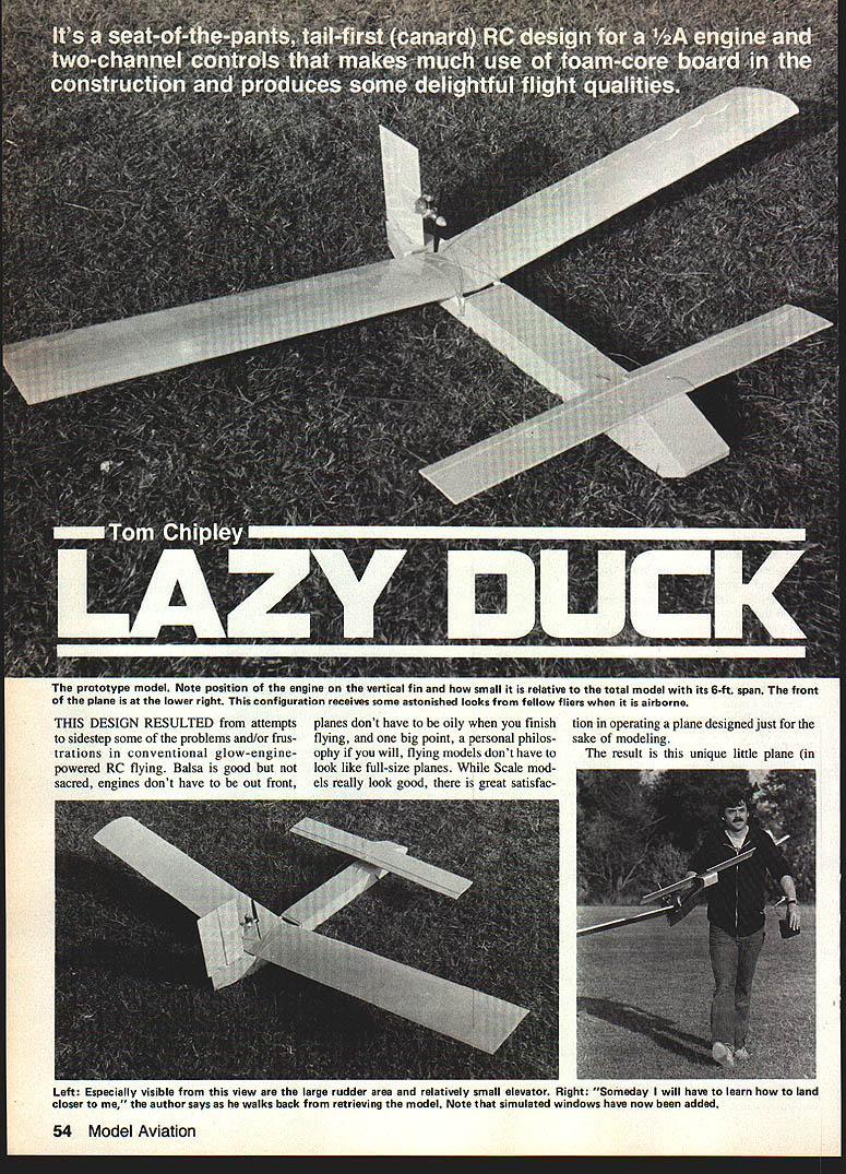
Tom Chipley
LAZY DUCK
This design resulted from attempts to sidestep some of the problems and frustrations in conventional glow-engine RC flying. Balsa is good but not sacred; engines don't have to be out front, planes don't have to be oily when you finish flying, and — a personal philosophy — flying models don't have to look like full-size planes. While scale models really look good, there is great satisfaction in operating a plane designed just for the sake of modeling.
The result is this unique little plane. Basically a powered glider, the canard configuration combined with a unique engine location and a mixture of materials gives the plane a personality of its own. Nothing quite like a canard, it arouses curiosity in both fliers and spectators on a Sunday afternoon. Many modelers familiar with the configuration are uncertain about building and flying one; because the layout is not common in full-scale practice, RC fliers often assume something must be inherently wrong. Actually, I have had very good luck. From the design’s outset the planes have flown with probably the easiest control arrangement. The design arrived by a mixture of scientific principles, the “eyeball,” and a bit of luck. It was sketched on paper, mocked up in cardboard, tested with a wing borrowed from a Drifter II — and one afternoon it flew right off the board.
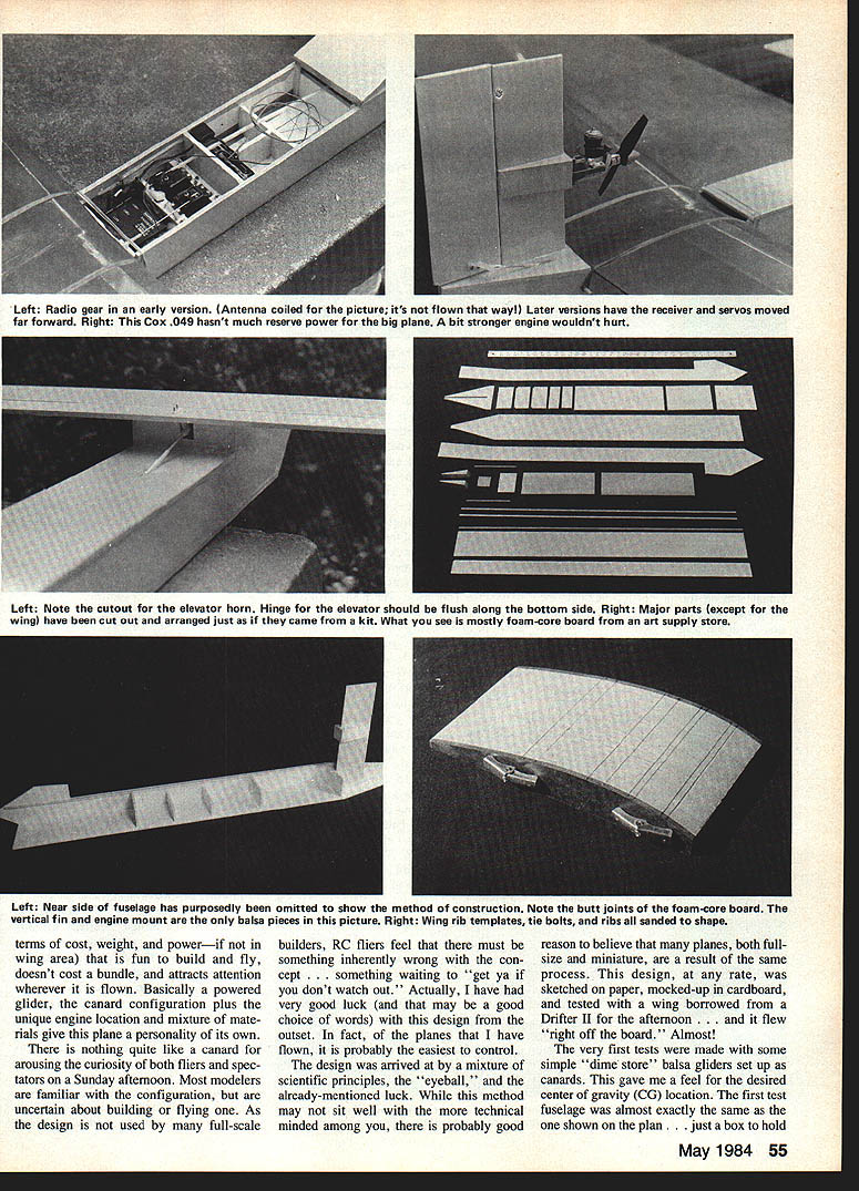
Almost the very first tests were made with simple dime-store balsa gliders set up as canards to get a feel for the desired center of gravity (CG). The receiver, servos and battery pack form a rigid group separated from the wing, horizontal stab and engine. These components were weighed and weight-matched with steel washers in a small plastic bag so the CG could be shifted easily.
During testing I discovered the importance of incidence between the wing and horizontal stab. With the horizontal stab glued flat (level with the fuselage centerline) the plane would nose over. Adding about three degrees to the stab produced a very smooth, flat flight. On the production version the stab has that built-in angle while the wing is mounted level. This gives a slightly nose-up cruise attitude in some setups and can make landings appear to be near-stalls when in fact they are slick and gentle.
Initial CG and test flights produced three important findings:
- A .049 engine will fly the plane provided enough thrust is available to maintain flying speed.
- The elevator is very sensitive; extreme care is required to prevent porpoising.
- When the engine stopped (ran out of fuel), the plane tended to pitch up slightly and then settle almost vertically with very little forward speed — a slow, gentle vertical descent with no flutter. After a few flights this characteristic was verified and then corrected by shifting the CG forward about an inch, which reduced elevator sensitivity and eliminated the vertical-descent tendency. The plane responded well to the change and could be flown easily with trim only.
Flight characteristics
- Rudder is adequate, but response at slow speed is less crisp; power-off turns are flatter and wider than some sport fliers may expect.
- With full power the plane is leisurely and sporty and can be flown in relatively confined areas. A slightly larger engine would increase forward speed and control responsiveness.
- Loops are possible only with buildup of forward speed using full power and a steep dive; with power off a loop is not achievable because terminal speed is insufficient.
- Stalls are very gentle and level unless rudder is intentionally applied. This makes the design a great trainer to learn hands/eyes coordination before moving to faster, more demanding planes.
- The rear-mounted engine avoids an oily fuselage and is less likely to be damaged in a nose-in landing. By mounting the engine on the leading edge of the vertical stab in a tractor (pulling) position, cooling and conventional starting/adjusting are easy — pusher props are not required.
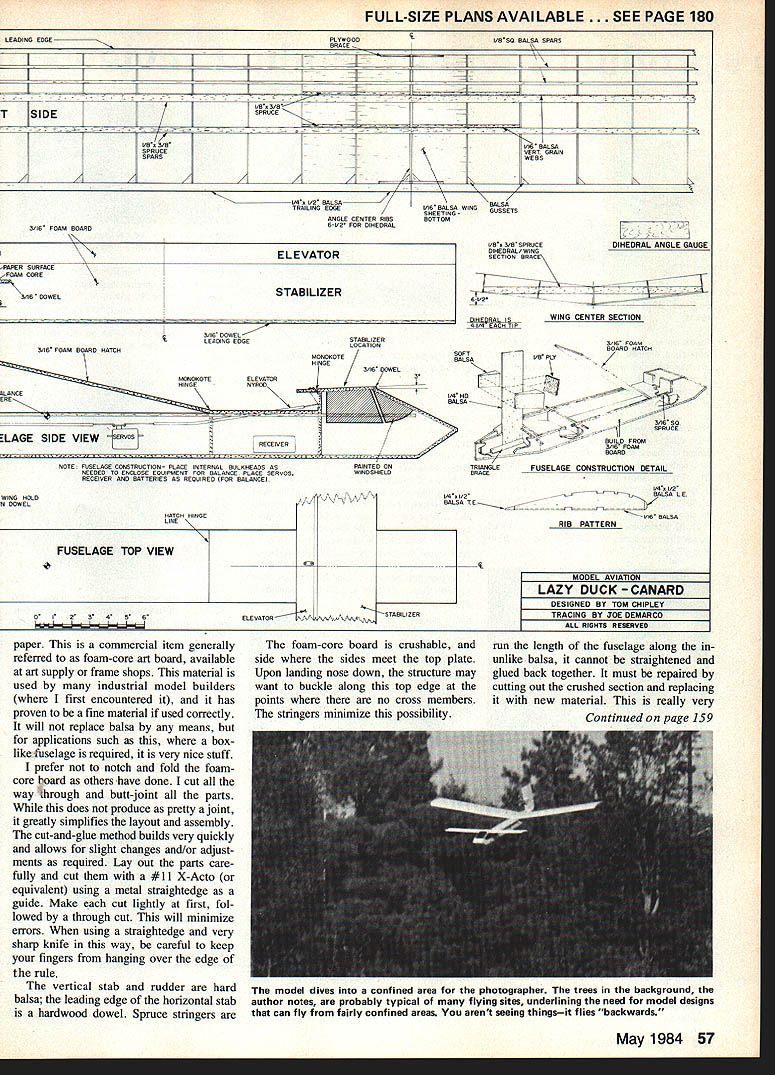
Construction
Materials overview
- Fuselage and horizontal stab/elevator: styrene foam-core art board sheeted with heavy paper (foam-core art board from art supply/frame shops).
- Vertical stab and rudder: hard balsa (1/4 in. fin and rudder recommended).
- Leading edge of horizontal stab: hardwood dowel.
- Spruce stringers: run the length of the fuselage along the inside for reinforcement.
- Wing spars: spruce (two spars; main spar webbed ~24 in., second spar webbed ~6 in.).
- Covering: iron-on covering such as MonoKote works well on the foam-core board.
The foam-core board is crushable; where the sides meet the top plate it may buckle on severe nose-down landings. Spruce stringers minimize this. Unlike balsa, crushed foam-core cannot be straightened and glued — repair by cutting out the crushed section and replacing it.
Fuselage and assembly
- I prefer to cut all the way through the foam-core board and butt-joint the parts rather than notching and folding. The cut-and-glue method builds quickly and allows slight adjustments.
- Lay out parts carefully and cut with a #11 X-Acto (or equivalent) using a metal straightedge. Make light initial cuts followed by a through cut; keep fingers away from the edge of the rule.
- The fuselage can be cut out and assembled in two evenings, allowing one day for white glue to fully dry. After building the basic box, locate components to achieve the correct balance point, then set in bulkheads as needed. With foam-core material, the added weight after balancing has little effect on performance.
Wing
- The wing is simple in structure but more time-consuming than the fuselage. Make rib templates from Masonite and sandwich rib blanks between them for sanding to final shape; use two long, small-diameter bolts to hold patterns and blanks together. This produces an identical set of ribs.
- I found a polyhedral design to be slightly more stable than a V-dihedral wing, but it requires more work to build and cover.
- Use two spruce spars for maximum strength. Join the two wing halves with sections of straight spruce epoxied in place so loads run straight through support members.
- Sheath the bottom of the wing for the first two rib bays with 1/16 balsa; reinforce the joint where two sheeted halves meet with a glue-and-fiber composite. I used a fibrous paper-like material (used locally to cover tobacco seedlings) soaked in glue as a strong, wrinkle-free reinforcement comparable to fiberglass without odor.
- Include gussets where ribs meet the trailing edge for extra strength. Wing tips are blocks of soft balsa sanded to shape.
Engine mount, tail and landing protection
- Engine mount: 1/8 plywood rectangle glued to two solid soft-balsa wedges, which are glued to the hard-balsa vertical stab. Build in about two degrees downthrust by sanding the wedges to shape (no side thrust needed).
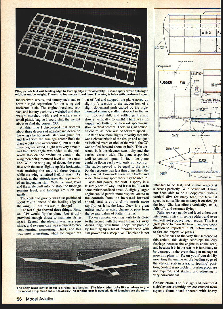
- Rudder hinge: use pinned hinges. On the prototype the rudder hinges backed out due to engine vibration and nearly caused a crash when the rudder locked; pin the hinges securely.
- Protect the leading edge of the horizontal stab with a hardwood dowel to prevent dings during belly landings. Because the stab is long, a blow near the outer end can break it loose; consider adding triangular stock on the inside joint of the stab and fuselage for reinforcement.
- For belly landings, the covering on the fuselage extends life; you may wish to attach hardwood runner strips to further protect the bottom.
Controls and radio
- Prototype used a Cox/Sanwa two-channel dry-cell transmitter and receiver. Nyrod-type pushrods were used because both rudder and elevator runs require some curving to reach their destinations.
- Elevator throw: kept to a minimum — not much is needed.
- Rudder throw: about 3/8 in. at the trailing edge each side of center.
- On the third stage prototype I used a strip of vinyl tape along the underside of the elevator/stab junction as a hinge. Since there is no fuel in that area, it need not be covered for protection; the tape hinge gives a smooth connection and prevents turbulence caused by loose flaps or poorly joined surfaces, which can noticeably affect flight.
Tips, variations and outlook
- The plane scores well in cost, weight, and power — if not in wing area. It is fun to build and fly, doesn't cost a bundle, and attracts attention wherever it is flown.
- It makes a great trainer and a relaxing change of pace from high-stress pattern flying. To keep awake, fly close to the ground during long, slow turns with the wing tip inches away.
- Details can be added for appearance: add black “windows,” wheels and a larger engine to permit real takeoffs and landings (a suggested next project). Or build the fuselage quickly and enjoy hand-launching and belly-landing for hours.
- If you have a wing of about 550 to 600 sq. in. surface area that you can borrow from another plane, you can just build the fuselage and carry it along for fun.
I am pragmatic in my hobby: I build efficiently and concentrate on what flies well without breaking the bank. The plans here are a starting point — add whatever detail you like, or keep it simple and have fun. Above all, this is a fun plane — let it be just that.
Transcribed from original scans by AI. Minor OCR errors may remain.

