
Lee-Richards No. 3
"How strange it would be if the solution to the problem of flight presented itself in the form of a wheel." — Mr. Winston Churchill, 1914.
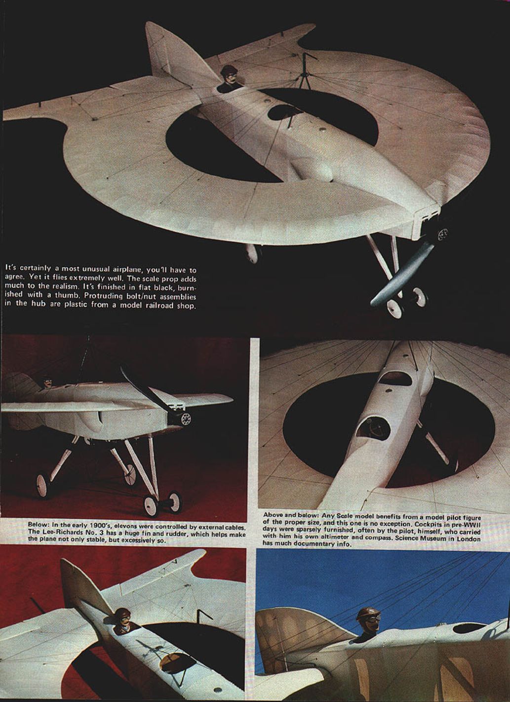
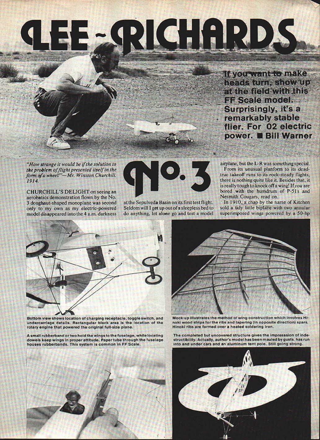
Churchill's delight on seeing an aerobatics demonstration flown by the No. 3 doughnut-shaped monoplane was second only to my own as my electric-powered model disappeared into the 4 a.m. darkness at the Sepulveda Basin on its first test flight. Seldom will I get up out of a sleepless bed to do anything, let alone go and test a model airplane, but the Lee–Richards (L‑R) was something special. From its unusual planform to its dead-true takeoff runs to its rock-steady flights, there is nothing quite like it. Besides that, it is really tough to knock off a wing! If you are bored with the humdrum of P-51s and Nesmith Cougars, read on.
In 1910, a chap by the name of Kitchen sold a tidy little biplane with two annular superimposed wings powered by a 50‑hp Gnome rotary to a well-to-do textile manufacturer and engineer, Cedric Lee. Lee, a member of the Manchester Aero Club, asked George Tilghman Richards to lend his engineering expertise to the project. This dynamic duo embarked on four years of work producing models and full-size aircraft with the annular wing concept, culminating in the very successful No. 3 which Churchill saw in flight.
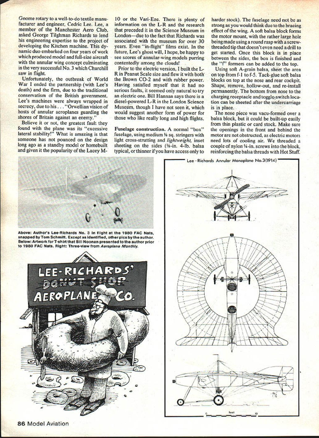
The outbreak of World War I ended the partnership (with Lee's death). Lee's machines were often wrapped in secrecy because of his—some said—Orwellian vision of hosts of annular aeroplanes guarding Britain’s shores. The greatest fault found with the plane was its "excessive lateral stability." What is amazing is that someone hasn't pounced on the design long ago as a standby homebuilt. There is plenty of information on the L‑R and the research that preceded it in the Science Museum in London—Richards was associated with the museum for over 30 years. Even "in‑flight" films exist. In the future, Lee's ghost will, I hope, be happy to see scores of annular-wing models purring contentedly among the clouds!
Prior to the electric version I built the L‑R in Peanut Scale and flew it with both the Brown CO‑2 and with rubber power. Having satisfied myself that it had no serious faults, it seemed only natural to try an electric one. Bill Hannan says there is a diesel-powered L‑R in the London Science Museum, suggesting another form of power for those who like really long, high flights.
Fuselage construction
A normal "box" fuselage is used:
- Medium 1/8‑in. square stringers with light cross‑strutting and lightweight inset sheeting on the sides (3/32‑in., 4‑lb. balsa typical; use thinner sheeting if you have harder stock).
- The fuselage need not be as strong as you might think due to the bracing effect of the annular wing.
Motor mount and nose:
- Form the motor mount from a soft balsa block. Make the rather large motor hole using a round rasp with a screw‑threaded tip; it doesn't even need a drill to get started.
- Once the block is in place between the sides, finish the box and add the "f" formers on top.
- Using soft A‑grain balsa, sheet the top area from F‑1 to F‑5. Tack‑glue soft balsa blocks on top at the nose and rear cockpit; shape, remove, hollow out, and re‑install permanently.
- The bottom from the nose to the charging receptacle and toggle‑switch location can be sheeted after the undercarriage is in place.
- The nose piece was vacuformed over a balsa block, but it could be built up from thin plastic or card stock. Make sure the openings in front of and behind the motor are not obstructed—electric motors need lots of cooling air.
- Thread a couple of nylon 4‑40 screws into the mount block, reinforcing the balsa threads with Hot Stuff.
- Wedging the motor using masking tape or balsa shims works well and is less trouble than complex mounts.
Fin and rudder
- Use light 4–6‑lb. C‑grain sheet for cores and cut out lightening holes.
- Build up the framework on both sides using 1/16‑in. sq. and 3/16 x 1/16 around edges.
- Attach the rudder with three lengths of 1/32‑in. music wire; use 1/32‑in. aluminum tube as bearings.
- The tail skid is a bent piece of 1/32‑in. wire with a short piece inside to prevent collapsing. Epoxy the tail skid to the rudder.
- Add scrap where the control horn passes through. Sand the entire tail assembly flush, leaving at least 1/32‑in. clearance each side.
- Keep the tissue covering the core.
Undercarriage
- Kingpost assemblies and wire assemblies are made to the plan lengths.
- Use 1/32‑in. music wire for most parts; main gear and kingpost parts j and k are 0.045‑in. dia. wire. You might use 0.045‑in. for parts b, i, d as well.
- Bind joints with fine brass wire and solder with Sta‑Brite; wash off acid flux to prevent rust later.
- Epoxy the undercarriage in place and add triangular gussets under the main gear for strength.
- Sheet the area underneath the nose to conform with the side sheeting; install the charging receptacle and engine toggle switch.
- Front landing gear legs are built up as sandwich units with the wire between two pieces of card stock. Rear landing legs are thicker—glue on a balsa sandwich and streamline to a teardrop section.
- The kingpost upper ends are inserted in a 1/16‑in. brass tube, flattened a bit and soldered. The ring "O" facilitates rigging and may be omitted if preferred. Insert the kingpost through the sheeting, epoxy in place, and bend the top portion above the brass tube 90° forward.
Wing construction
- The wing is made from three parts which form a "floor" on which everything else is built.
- Use 1/20 or 1/16 lightweight C‑grain sheet for the floor, observing grain directions shown on the plan.
- Add 3/16‑in. solid ribs at each end. Build up the leading and trailing edges by cementing on flexible 3/32‑in. balsa strip.
- Mark the positions of the spars on the "floor" and glue them in place. Super Jet or Super‑T cyanoacrylate cements are ideal for installing the spars.
Spars and ribs:
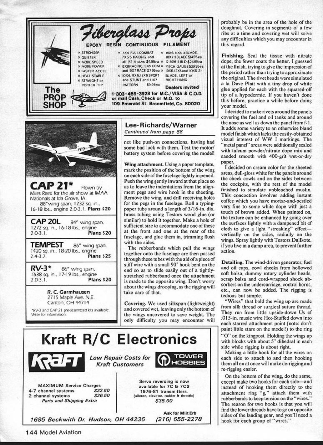
- The tail end of Spar A butts against Rib W‑1; the short end of Spar B goes against W‑1. This gives a smooth and constant transition so the airfoil has a continuous shape with the nose of the rib pointing forward at both front and rear.
- The original full‑size had a more abrupt transition; the model is a bit simpler. Purists may obtain original data from the Science Museum.
Hinoki strips and rib installation:
- Hinoki wood is strong, light, and bends well when wetted. A packet of 25 strips, 17 in. long, may be obtained from specialty suppliers.
- Wet one end of a Hinoki strip and form it over the large diameter of a heated soldering iron, pulling back and forth while bending so as not to burn it.
- Cut each rib to proper length and glue between L.E. and T.E., down onto the spars.
- After all Hinoki strips are in place, add a length of 1/16‑in. sq. balsa under the center of the ribs (equidistant from the spars) and glue to each rib.
- Scrap balsa glued in at the starred locations will provide anchor points for rigging after covering.
- Sand the wing so the airfoil shape continues around a nicely contoured L.E. and T.E.
Control surfaces and fittings:
- The "elevator‑cum‑aileron" (elevon) is mounted using two pieces of 1/32‑in. music wire and sanded to the correct tapered profile.
- Add locating pegs and rubber hooks at W‑1 and W‑34. Bend the far end of the hook wire (1/32‑in. music wire) down 90° to prevent pullout.
- Build the second wing "back to back" with the first to avoid making two left wings.
- Optional music wire abrasion guards can be added before covering to protect the L.E. and elevon tips if flying over asphalt.
Power plant
- Follow the Astro‑Flight O‑2 electric motor manufacturer's instructions for hooking up the motor.
- I prefer to arrange the batteries longitudinally on the bottom of the plane rather than in a little "four‑pack," holding them together with Magic Mending Tape and Hot Stuff. Do not glue the batteries down until final trimming—battery location determines the correct center of gravity without adding extra weight.
- Leave a couple of inches of wire at the motor and batteries so each can be extracted for service.
- A ventilated battery box would be nice; I typically cut into the tissue to replace batteries in the field. Carry a portable soldering iron and solder connections at the field; avoid tiny push‑on connectors—they can work loose with vibration.
- After the radio installation, balance the plane. I use a 5/32‑in. brass tube in the C.G. location to accept a small rod for hanging the plane on the flight line—this makes trimming easier.
- Test the motor/battery system before covering the model.
Wing attachment and covering
Wing attachment:
- Using a paper template, mark the position of the bottom of the wing on each side of the fuselage with a light pencil line.
- Push the wing gently inward at those positions to leave indentations from the alignment pegs and wire hooks in the sheeting. Remove the wing and drill receiving holes for the pegs in the fuselage.
- Roll a typing‑paper tube around a length of 3/16‑in. dia. brass tubing using Testors wood glue (or similar). Make a hole of sufficient size to accommodate one tube at the front and one at the rear of the fuselage and glue them in, trimming flush with the sides.
- Pass the rubber bands which pull the wings together through these tubes using a piece of stiff wire with a small 90° hook on the end to aid threading. Don’t worry about wing droop—the rigging will take care of that.
Covering:
- Use light silkspan and cover wet, leaving only the bottom of the wings uncovered to save weight.
- The doughnut hole can be tricky—cover in small segments of a few ribs at a time and work wet to manage the curvature.
- Seal the tissue with nitrate dope—use as few coats as necessary.
Finishing:
- Simulate rivet heads by applying tiny drops of white glue (use a blunt tool such as the squared‑off tip of a hypodermic) and practice before applying to the model.
- Make rivets around panels (fuel and oil tanks, nose, panel from F‑1) to add visual interest.
- "Metal panel" areas were sealed with a talcum powder/nitrate dope mix and sanded smooth with 400‑grit wet‑or‑dry paper.
- Color scheme: cream for the sheeted areas, dull‑gloss white for panels around cheek cowls and between cockpits, and the rest to simulate unbleached muslin. Tint white dope with a touch of brown and a little instant coffee (finely ground and mortar‑and‑pestled) to get the muslin tone. When painted on, enhance the texture by lightly stroking with a damp cloth—vertically on the sides, radially on the wings.
- Spray lightly with Testors DullKote if you live in a damp area to inhibit further action.
Detailing and rigging
- Add wind‑driven generator, fuel and oil caps, cowl cheeks (hollowed soft balsa), dummy rotary cylinder heads, scrap balsa details, cord‑wrapped shock absorbers on the undercarriage, control horns, etc.
- Rigging wires that hold the wing up are made from silk thread or surgical suture thread. They run from little upside‑down U's of 0.015‑in. music wire, Hot‑Stuffed down into each starred attachment point, to the ring "O" on the kingpost.
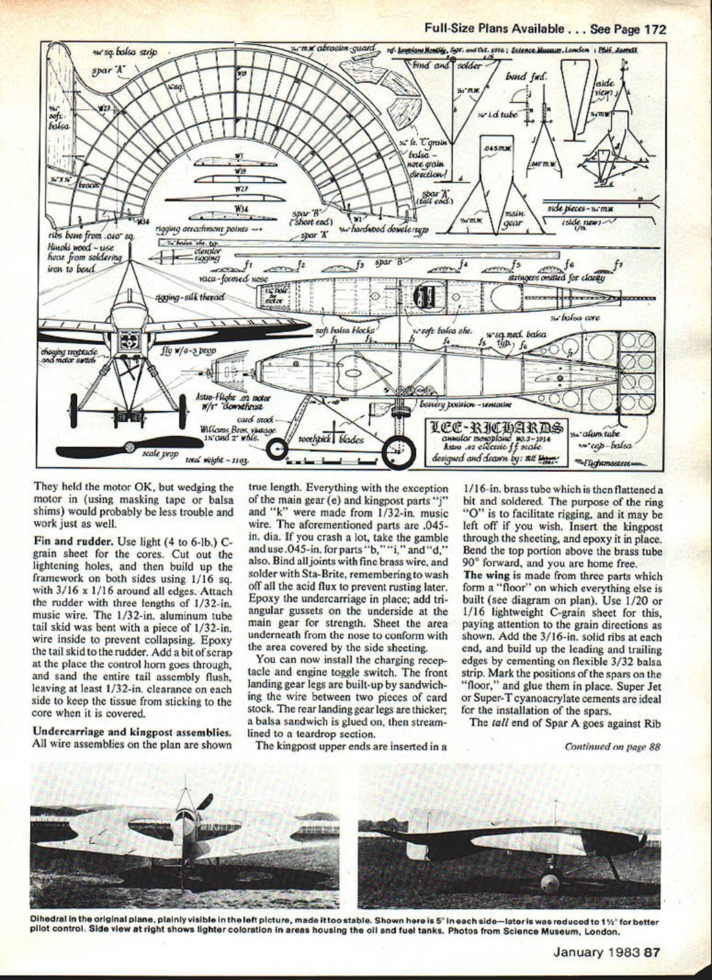
- Hold the wings up with blocks to give about 5° dihedral on each side while rigging.
- Make a small hook assembly for all the wires on each side so you can hook them all on and off at once—this eases de‑rigging and re‑rigging.
- On the bottom of the wing, make two hooks for each side; attach these with rubber bands to keep tension on the wires. Two hooks are needed because the lower threads must pass on opposite sides of the landing gear.
Controls and flying
- Rig the control "wires" for the elevons and rudder as shown on the plan. Both sides are the same.
- Locate your C.G. by shifting the batteries as shown on the plan, then Hot‑Stuff them in place.
- Charge the batteries about one minute at 2 amps (or at the low position on the Astro‑Flight charger) for an initial flight.
- Launching:
- Hand‑launch if you have tall grass.
- R.O.G. (rise off ground) if you have asphalt.
- If the elevons and rudder are neutral, the model should fly. Correct any diving tendency with tiny, equal up bends to both elevons.
- Stalling can be cured by adding modeling clay at the front wheel strut intersection.
- When the model flies in a wide left‑hand circle, it is happy. If you have to add clay, note the final balance point and move the batteries forward to compensate.
- For contest and most normal flying, a two‑minute charge at 2 amps will be adequate. You can go longer, but don't risk expensive batteries unnecessarily.
- Improved performance can be gained by using four Sanyo 3/4‑in. Ni‑Cd pen cells, or by using a weak .049 glow engine.
- If you cannot keep the electric model's weight near 11 oz., the glow engine solution might be preferable—just remember fuel‑proofing.
Finally, if anyone cracks that it looks like a "flying toilet seat," either poke 'em in the nose, or tell 'em it's really an annular wing—which, in the words of Dr. Dzus of Escondido, means it comes around only once a year!
Transcribed from original scans by AI. Minor OCR errors may remain.

