
Let's Talk About: Airplane Design
Brad Powers
Prologue
In the October issue my article consisted of 20 questions on airplane design. As it turns out, I only got a grade of 90%. I missed the one on P-factor, and as a result I gave bad advice about propeller swing on twin-engine designs.
During and after WWII (1939–1952) I was a preliminary design engineer at Convair. In those days P-factor was unheard of. When, many years later, I read a brief description about it in a flight manual, I simply dismissed it as a simplistic explanation of the effects of torque. It did not appear in any aerodynamic texts that I was aware of, nor had any of my old cohorts heard of it (probably because, in those days, we were designing large jet-powered aircraft where P-factor was not a consideration).
Since then, however, an engineer named Ribner at NACA has shown that P-factor is a valid notion after all, and it contributes additionally to yaw at takeoff, especially on tail-draggers and when approaching the stall. This does not negate torque; it is in addition to it. This being true, it turns out that propeller rotation acting "in and down" with respect to the fuselage on twin-engine designs is preferable to "up and out" as I had said. More on this will be in a future article on torque.
I thus missed two of my own questions. I apologize to the readers for giving wrong information, and I thank those who politely pointed out my error.
Information about lift coefficients and how to use the Lift Equation are the topics this month. Part 2.
The Lift Equation. In the engineering profession there are certain hard criteria. For example, to be an electrical engineer one is expected to at least know Ohm's Law, I = E/R. To be a structural engineer one should really be familiar with the formula for bending, f = My/I. In the same way every aerodynamicist worth his salt should have some awareness of the basic Lift Equation:
L = C_L q S
If we learn to use this equation we can find the answers to the sort of problems that follow. We will have an understanding of how weight, wing area, speed, etc., are interrelated. Here are some problems together with the answers. At the end of the article we will be able to check the answers.
- Harry wants to build a quarter-scale model that will land slowly and realistically at about 25 mph. He figures it will weigh 30 lb., and he knows that a value for C_L of 1.0 is about the best he can expect. What should his wing area be?
- Answer: 18 sq. ft.
- Jim, on the other hand, is interested in speed. His pylon racer can fly at a C_L of 0.04 at full power. If his racer weighs five pounds and has a wing area of 3.125 sq. ft., how fast will it fly in still air?
- Answer: 125 mph.
- Larry has designed an airplane but is concerned about its weight. He wants to land it at 25 mph or less. It has a wing area of 6 sq. ft. and has flaps, allowing it to develop a C_L of 1.5. How much can his airplane weigh?
- Answer: 144 lb.
- Gary is intrigued by MacCready's Gossamer Condor. He wants to build a model having similar slow-flight characteristics. If he wants the model to "cruise" at 15 mph at a C_L of 0.5, what should the wing loading be?
- Answer: 0.29 lb. per sq. ft. (about 4.6 oz. per sq. ft.)
- If, in the above problem, Gary's wing area is 20 sq. ft., what must the model weigh?
- Answer: 5.8 lb. (To achieve such slow flight the model must be very light; Gary might consider carbon-fiber spars and other weight-saving features.)
- Assuming I have adequate power, if my wing area is 6 sq. ft. and weight is 10 lb., at what speed will it fly at C_L = 0.3, C_L = 0.6, and C_L = 0.9?
- Answers: C_L = 0.3 → 46 mph; C_L = 0.6 → 33 mph; C_L = 0.9 → 27 mph.
- What angles of attack do these speeds represent?
- Answers: 4 degrees, 8 degrees, and 12 degrees.
- How much speed will I gain (as a percentage) if I build a new wing with half the area (weight remains the same)?
- Answer: 40% greater speed.
- As a percentage, what will doubling the wing area do to my speed (no weight change)?
- Answer: 70% as fast (i.e., 30% slower).
- If I reduce weight by 20%, what will this do to my landing speed?
- Answer: It will reduce landing speed by 11%.
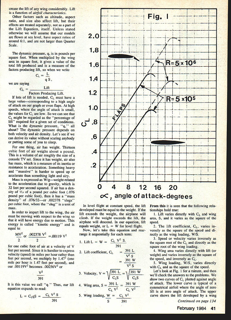
Fig. 1 shows a lift curve for which the lift coefficient, C_L, is plotted against angle of attack, usually denoted by α. From time to time articles appear showing curves like this, but rarely are they explained. I think that most readers haven't the faintest idea what a lift coefficient is, so perhaps we should assume that some of you are honestly curious about such things.
First, let's rearrange our equation and put it in terms of the lift coefficient, C_L:
C_L = L / (q S)
Where:
- C_L is a pure number (a ratio).
- L is the lift in pounds.
- q is the dynamic pressure in pounds per square foot.
- S is the wing area in square feet.
Fliers have learned that lift is affected by several things:
- When we apply extra power, we not only increase the speed of the airplane, but we usually find ourselves applying control or trim to keep from climbing too high. So lift is a function of airspeed.
- When we land we usually cut the throttle and increase the angle of attack to maintain lift at low speed. Lift is also a function of angle of attack.
- At a given speed, a model with a large wing will develop more lift than one with a small wing. Lift is a function of wing area.
- In cold, dry weather takeoff runs are generally shorter than in hot, moist weather. They are also shorter at sea level than in Denver or Mexico City. Lift is a function of air density.
- Some thick, highly cambered airfoils develop more lift than thin, flat ones having the same wing area. The use of flaps will increase the lift of any wing considerably. Lift is a function of airfoil characteristics.
Other factors such as altitude, aspect ratio, and size also affect lift, but their effects are treated separately, not as a part of the Lift Equation itself. Unless stated otherwise we will assume our models are flown at sea level, have aspect ratios around 6:1, and are not larger than quarter scale.
The dynamic pressure, q, is in pounds per square foot. When multiplied by wing area (S), it gives the total lift produced and is a measure of the factors producing lift. Thus:
C_L = Lift / (Factors Producing Lift).
If lots of lift is needed, C_L must have a large value—corresponding to a high angle of attack or even flaps. At high speeds, where the angle of attack is small, values for C_L are low. C_L might be regarded as the "percentage of lift" required for a given set of conditions.
What is the dynamic pressure, q? The dynamic pressure depends on both velocity and air density.
Air has weight: about 13 cubic feet of air weigh approximately one pound (≈0.076 lb/ft^3). Since it has weight, air also has mass, which is a measure of its inertia or resistance to acceleration. Mass is expressed as W/g — weight related to the acceleration due to gravity, g ≈ 32 ft/s^2. If air has density 0.076 lb/ft^3, then it has a mass density of 0.076/32 ≈ 0.002378 slugs per cubic foot (the slug is a unit of mass).
To impart lift to the wing, the air must be moving relative to the wing and thus has kinetic energy. The kinetic energy per cubic foot of air is:
( mass × V^2 ) / 2 = 0.002378 × V^2 / 2 = 0.00119 V^2 (V in ft/s)
Converting V from ft/s to mph (1 mph = 1.467 ft/s), this becomes approximately 0.00256 V^2, which is the dynamic pressure q. That value can be written as:
q = 0.00256 V^2 = V^2 / 391
Thus our lift equation becomes:
L = C_L q S = C_L V^2 S / 391
In level flight at constant speed, lift equals weight, so L = W. Rearranging sequentially:
- Lift: L = W = C_L V^2 S / 391.
- Lift coefficient: C_L = 391 L / (V^2 S) = 391 W / (V^2 S).
- Velocity: V = sqrt(391 L / (C_L S)) = sqrt(391 W / (C_L S)).
- Wing area: S = 391 L / (C_L V^2) = 391 W / (C_L V^2).
- Wing loading: W / S = C_L V^2 / 391.
From these we see the following relationships:
- Lift varies directly with C_L and wing area S, and varies as the square of the speed.
- The lift coefficient C_L varies inversely as the square of the speed and directly as the wing loading W/S.
- Speed varies inversely as the square root of C_L and directly as the square root of the wing loading.
- Wing area varies directly with lift (or weight) and varies inversely as the square of the speed and inversely as C_L.
- Wing loading W/S varies directly with C_L and as the square of the speed.
Now, a few notes about the lift curve (Fig. 1). We show two curves of C_L plotted against angle of attack. The lower curve is typical of a symmetrical airfoil where zero lift occurs at zero angle of attack. The upper curve shows the lift developed by a cambered wing; the angle for zero lift would be shifted left to a negative angle of attack, and the curve rises above that for the unflapped section.
Because of Reynolds number effects, a model wing can only reach a maximum C_L of about 1.0 without flaps. Flaps can increase this to about 1.5. A full-size wing can reach much higher lift coefficients because full-size Reynolds numbers are much larger.
Reynolds number (R) ≈ 10,000 × mph × chord (in feet). A model with a 1 ft chord flying at 50 mph operates at R ≈ 500,000 — indicated by the solid parts of the curves — while a full-size airplane operates at R values into the millions. At low Reynolds numbers the flow over the wing breaks down readily; the wing typically stalls at about 12 degrees, depending on aspect ratio, wing loading, and other factors.
Now, let's check the answers to the problems using the equations above.
- Harry's wing area (Equation 4):
S = 391 W / (C_L V^2) = 391 × 30 / (1.0 × 25^2) = 18.76 → 18 sq. ft.
- Jim's speed (Equation 3):
V = sqrt(391 W / (C_L S)) = sqrt(391 × 5 / (0.04 × 3.125)) = 125.06 → 125 mph.
- Larry's weight (Equation 1):
W = C_L V^2 S / 391 = 1.5 × 25^2 × 6 / 391 = 144 lb.
- Gary's wing loading (Equation 5):
W/S = C_L V^2 / 391 = 0.5 × 15^2 / 391 = 0.29 lb/ft^2 (≈4.6 oz/ft^2).
- Gary's weight with S = 20 ft^2:
W = 0.29 × 20 = 5.8 lb.
- For W = 10 lb and S = 6 ft^2, V = sqrt(391 W / (C_L S)):
- C_L = 0.3 → V = sqrt(391 × 10 / (0.3 × 6)) = 46.6 → 46 mph.
- C_L = 0.6 → V = sqrt(391 × 10 / (0.6 × 6)) = 32.9 → 33 mph.
- C_L = 0.9 → V = sqrt(391 × 10 / (0.9 × 6)) = 26.9 → 27 mph.
- These speeds correspond to angles of attack of approximately 4°, 8°, and 12°, respectively.
- How much speed will you gain by halving wing area (weight same)?
Halving S doubles the wing loading W/S. Speed varies as the square root of wing loading, so V increases by sqrt(2) ≈ 1.4 → 40% faster.
- Doubling wing area (no weight change) halves W/S. Speed decreases by sqrt(0.5) ≈ 0.707 → 70% as fast (30% slower).
- Reducing weight by 20% reduces wing loading to 80% of original. Speed scales with the square root of wing loading: sqrt(0.8) ≈ 0.894 → landing speed reduced by about 11%.
- (Discussion) From this we see that V varies inversely as the square root of the ratio of lift coefficients. For example, the C_L for 46 mph is 0.3 and for 33 mph is 0.6; the ratio 0.3/0.6 = 1/2. The square root of 1/2 is 0.707, and 46.6 × 0.707 ≈ 32.9 mph, matching the calculation.
You can read the answers directly from Fig. 1. The relationships above explain why changes in wing area, C_L, and weight have the effects calculated.
Even with the math it wasn't so complicated and mysterious, was it? In the future I will try to minimize the math as much as possible, but some things are difficult (if not impossible) to express any other way. Mathematics is a useful and beautiful human accomplishment. Without it we would all be back in the stone age wondering how to divide three bird's eggs among four people.
Epilogue
The subject of aerodynamics is more complex than I have tried to make it seem, but it is my intention in these articles to expose the reader to the subject in a rational but light fashion—yet give some useful formulas and relationships. For example, to say that a C_L of 1.0 is typical for models is generally true, but the effects of aspect ratio, airfoil selection, etc., can change this somewhat.
I am trying to take a complicated subject and put it in fairly simple terms that can be digested by the average reader. I hope this discussion on the Lift Equation has been of interest to those of you who want to know more about design.
Questions and comments may be addressed to Brad Powers, 5470 Castle Hills Dr., San Diego, CA 92109.
Transcribed from original scans by AI. Minor OCR errors may remain.

