
Let's Talk About Airplane Design
Brad Powers
It was in 1978 when I first submitted an article to Model Aviation entitled "About the Size of It." Presented was an exercise in dimensional analysis that explained how things such as weight, speed, power, etc., vary with size or scale. I tried to make the material understandable to a "bright 12-year-old," and while it was well-received by readers, the letters I received were, for the most part, from modelers in their 50s and 60s — people like myself who had rekindled a youthful interest in modeling. No 12-year-olds, bright or otherwise, seemed to be reading the stuff. At least, they didn't correspond. I think this is too bad because there is something spellbinding about model airplanes that seems to stay with one all his life.
In any case, the letters from readers indicated that many are quite knowledgeable, and one who presumes to write articles had better not make blunders lest he incur the wrath of the "experts."
In the article in the December 1984 issue I stated that "...a cambered airfoil alone exhibits a positive moment...." This was a case of sloppy proofreading of my own material before sending it in to the magazine. What I meant to say: "A cambered wing alone exhibits a negative moment, but when attached to a fuselage having no tail, the combination generally produces a positive moment." Needless to say, I received a lot of mail about that one.
I also received some mail for saying that decalage is one of the criteria for stability. While I realize that decalage is really a form of trim and not a stability parameter, it is nevertheless fundamental to flight itself, and in the case of tailless designs, it does, in fact, become closely allied with stability.
Why cambered sections have negative (diving) moments
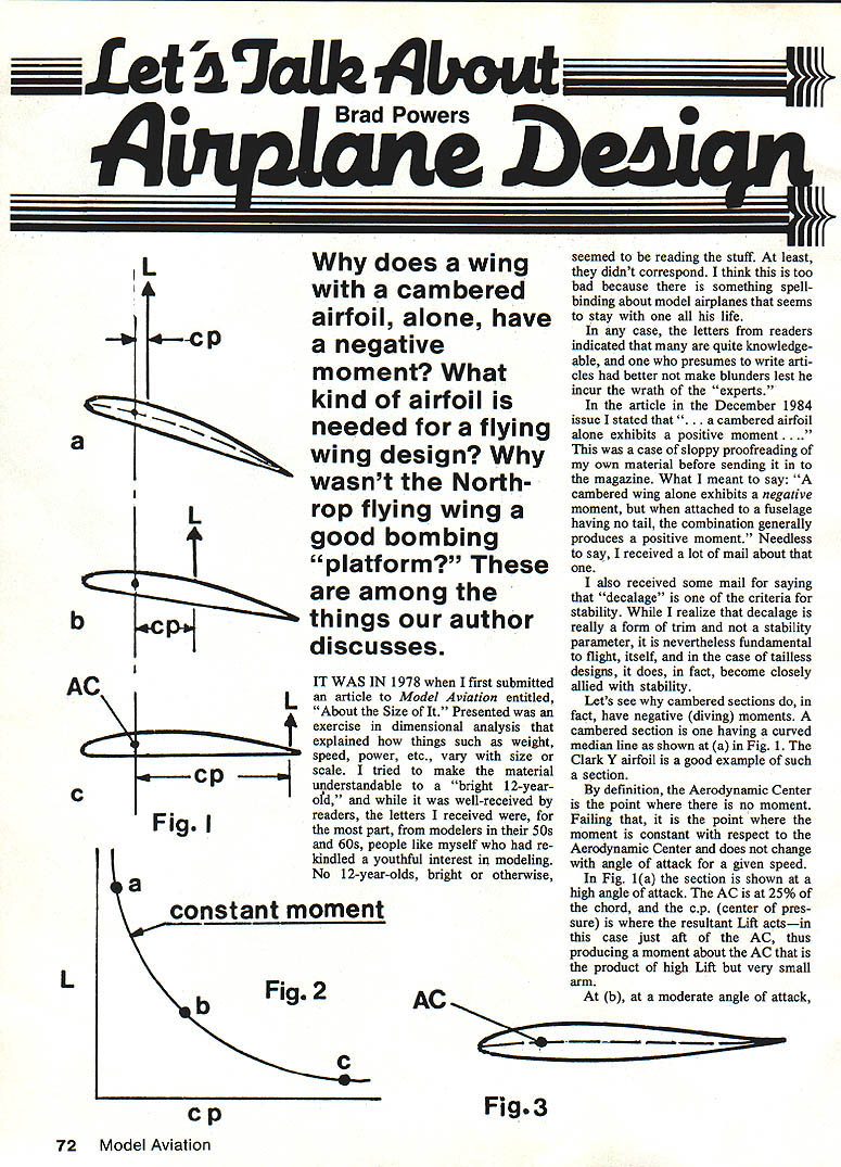
A cambered section is one having a curved mean line (see Fig. 1a). The Clark Y airfoil is a good example of such a section.
By definition, the Aerodynamic Center (AC) is the point where there is no change in moment with angle of attack — the moment about the AC is essentially constant with angle of attack for a given speed.
In Fig. 1(a) the section is shown at a high angle of attack. The AC is at 25% of the chord, and the center of pressure (c.p.) is where the resultant lift acts — in this case just aft of the AC, thus producing a moment about the AC that is the product of high lift but a very small arm.
At (b), at a moderate angle of attack, the c.p. is further aft; the product of lift and moment arm again produces essentially the same moment. At (c), at a very small angle of attack, the lift is also very small but acts much farther back near the trailing edge and again produces an equivalent moment.
So we can infer that for a given speed the moment about the AC will be essentially constant; it will lie on the curve of "constant moment" shown in Fig. 2. The moment will be negative (a diving moment) because the lift acts aft of the AC tending to pitch the nose down. Such an airfoil is said to be unstable — i.e., it cannot be made to fly itself and must have a trimming surface either behind it (conventional design), in front of it (canard), or incorporated as part of a tailless design.
Such a trimming surface must be set at the angle required to trim the wing and keep it from pitching down. The angular difference between the two surfaces is called decalage (sometimes called longitudinal dihedral — a misnomer since it has nothing to do with dihedral).
Tailless designs and stable airfoils
Earlier I discussed stability of the conventional configuration and said a stable airplane must have the CG forward of the neutral point, defined as the AC of the whole airplane. Now let's see how that applies to a tailless design.
Obviously you can't use an unstable cambered airfoil if you don't have a tail to trim it. So you will have to use a stable airfoil such as shown in Fig. 3. Its mean line turns up near the trailing edge causing the nose to pitch up rather than down as in the Clark Y example. With proper placement of the CG such a wing alone can be made to fly in a stable fashion.
Turning up the trailing edge has the effect of moving the AC forward a bit, usually to about 23%–24% of the chord. The neutral point for the stable airfoil is a point aft of the CG; the CG must be forward of it for stability to be maintained.
Since decalage is short-coupled, the upturned trailing edge is like a tail limited too far forward. The CG can be placed fairly far forward and still have good pitch control — about 20% chord MAC is as far forward as practicable. The result is tailless designs have a very limited permissible CG travel range — about 3% MAC. This limited CG range is the reason Northrop's flying wing wasn't a very successful bomber: there was too little CG travel to provide a good bombing platform, whereas conventional designs with long tails, such as the B-24 and B-17, are comparatively steady for the purpose.
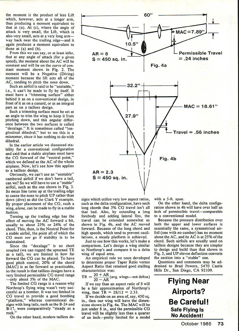
On the other hand, modern tailless designs utilize very low aspect ratios (such as the delta configuration) which have such long chords that the 3% CG travel isn't all that bad. Also, by extending a long forebody and adding lateral fins in a clever way (see Fig. 4b), the CG can be extended somewhat and the AC moved forward. Because of the long chord and high speeds, which tend to prevent oscillations, a steady platform is achieved.
A simple comparison: Northrop-like wing vs. delta wing
To illustrate, let's make a comparison. Design a wing similar to Northrop's and compare it to a delta wing of equal area.
- We used an empirical rule to determine proper taper ratio (TR) versus aspect ratio (AR) that retained good stall characteristics for average wings (not deltas):
- TR = (20 + AR) / (20 − AR)
- If AR = 8 (a fair approximation of Northrop's wing), then:
- TR = (20 + 8) / (20 − 8) = 28 / 12 ≈ 2.33
- If we choose an area of 450 sq. in., the conventional wing (Fig. 4a) will have the dimensions shown. The MAC will be just under 8 in., and the permissible CG travel will be slightly less than a quarter of an inch — pretty limited for a model with a 5-ft span.
- By contrast, the delta configuration (Fig. 4b) will have over half an inch of permissible CG travel — comparable to a conventional model.
Because the pressure distribution over both the upper and lower surfaces is essentially the same, a symmetrical airfoil (one with no camber) has no moment about the AC, and its AC is at 25% of the chord. Such airfoils are usually used on tailless designs because they are simpler to design and build than the upturned trailing-edge section shown in Fig. 3, and up-elevator deflection converts the section into a "stable" one.
Questions and comments may be addressed to Brad Powers, 5470 Castle Hills Dr., San Diego, CA 92109.
Transcribed from original scans by AI. Minor OCR errors may remain.

