
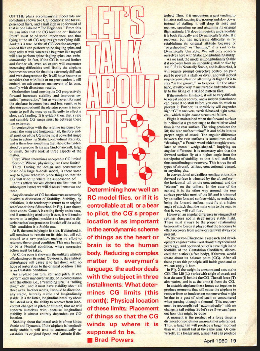

Let's Talk About The CG
On the plans accompanying model kits, two CG locations are sometimes shown: one for experienced fliers and a half inch or so forward of that labeled "For Beginners." From this we can infer that the CG location, or "balance point," is important, and that flying at the aft CG requires greater skill. This is true. At the aft CG location an experienced flier can perform spine‑tingling spins and snap rolls at will, whereas a beginner like myself will also perform spine‑tingling spins, etc., unintentionally. If the CG is moved further and further aft, even an expert will encounter increasing difficulties until finally the airplane becomes so unstable that it is extremely difficult and even dangerous to fly. It will have become so sensitive that with little or no provocation it will embark on adventurous maneuvers of its own, usually with disastrous results.
On the other hand, moving the CG progressively forward increases stability and improves so‑called "penetration." But as we move it forward, the airplane becomes less and less sensitive to elevator control until the elevator power is inadequate to pull the nose up sufficiently to effect a slow, safe landing. It is evident, then, that a safe and sensible CG range must lie between these two extremes.
In conjunction with the relative incidence between the wing and horizontal tail, the fore‑and‑aft position of the CG is the most powerful single factor in achieving static longitudinal stability, and is therefore something that should be understood by anyone flying any kind of aircraft, large or small. So let's look at three aspects of the matter.
Three aspects to consider
- What determines acceptable CG limits?
- Where, physically, are these limits?
- During the design and construction phase of a large 1/4‑scale model, is there some way to figure where to place things so that the CG will wind up where it's supposed to be?
In this article we will discuss the first item. In subsequent issues we will discuss items two and three.
Any discussion of CG location must necessarily involve a discussion of stability. Stability, by definition, is the tendency to return to an original set of conditions if disturbed.
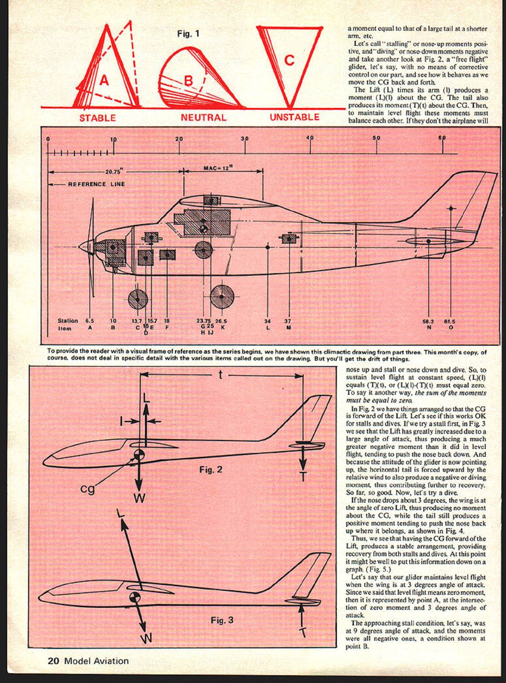
In Fig. 1 three cones illustrate this:
- Cone A is resting firmly on its base. If tipped, it tends to return to its original position (as long as the disturbance isn't so great as to knock it off the table). This is a stable condition.
- Cone B is lying on its side. If disturbed, it will remain on its side and roll to a new position, making no effort to return to the original condition. This is a neutral condition.
- Cone C balances on its point. The slightest disturbance will cause it to fall with no hope of restoration to the original position. This is an unstable condition.
An airplane can yaw, roll and pitch; it must have stability about all three axes — directional, lateral and longitudinal. We will concern ourselves with longitudinal stability (stability about the lateral axis), the ability to recover from inadvertent changes in pitch attitude, because longitudinal stability is almost entirely dependent on CG location.
Stability about the lateral axis is of two kinds: static and dynamic. If the airplane is longitudinally stable it will tend to automatically re‑establish its original speed and attitude if disturbed. Thus, if it encounters a gust that tends to initiate a stall (causing it to nose up and slow down), instead of stalling it will drop its nose, recover, speed up, and assume its original flight attitude. If it does this quickly and smoothly it is both statically and dynamically stable. If it recovers but has increasing difficulty reestablishing its original attitude because of overshooting or hunting, it is dynamically unstable. Here we will concern ourselves only with static longitudinal stability.
A model is longitudinally stable if it recovers from an impending stall or dive by itself. If it is neutrally stable and is disturbed, it will require prompt corrective control to prevent a stall or dive, and will demand attention throughout the flight to stay "in the groove." Such a model will be very maneuverable and may suit a skilled pattern flier. If the model is unstable, it will be very difficult to keep under control; a sudden disturbance can cause it to stall before you can prevent it. Its sensitivity can engender high‑G maneuvers that might cause structural failure.
Flight is maintained when the forward surface is inclined at a greater angle to the relative wind than the rear surface. The wing produces the lift; the rear surface trims it and holds it to its proper angle of attack. The angular difference between the two surfaces is sometimes called decalage, a French word roughly translating to "wedge‑shaped," implying an angular difference. It is necessary that the forward surface fly at a higher angle from the standpoint of stability so that it will stall first, contributing to recovery. This is true for all types of aircraft: tailless, conventional, canard, or others.
In conventional and tailless configurations the forward surface is trimmed by the aft surface — the horizontal tail on the conventional and the elevon on the tailless. In the canard the situation is reversed: the rear surface provides most of the lift and is trimmed by a smaller forward surface which, being forward, must nevertheless fly at a higher angle of attack than the main wing so that it stalls first.
However, an angular difference in wing and tail settings does not in itself ensure stable flight. There must be the proper relationship between the forces at play so that the tendency to recover from a dive or stall will always be present.
Wernher von Flintstone, a research and development engineer who lived about thirty thousand years ago and operated out of a cave high in the foothills of the Cantabrian Cordillera, discovered that a stick (a free body), if thrown, would rotate about its center of gravity (CG). After all these years this principle still holds and can be applied here.
In Fig. 2 the weight is constant and acts at the CG. The wing lift (L) varies with angle of attack and acts at the arm (l) behind the CG. The tail force (T) also varies and acts at the arm (t) from the CG. In a stable airplane these forces produce moments that will cause the airplane to recover from an inadvertent maneuver (such as a gust encountered when passing through a thermal). This recovery must be accomplished automatically with no change in throttle setting.
A moment is the product of a force times a distance. Thus, a large tail will produce a larger moment than a small tail at the same arm. Conversely, at a longer arm, a small tail can produce a larger moment than a larger tail at a shorter arm.
Reducing the complex matter to everyday language, the subject can be treated in three installments: what determines CG limits (this month); the physical location of these limits; and placement of components so the CG winds up where it is supposed to be.
If we call stalling or nose‑up moments positive and diving or nose‑down moments negative, consider Fig. 2 — a "free flight" glider with no corrective control. The wing lift L times its arm l produces a moment (L)(l) about the CG. The tail produces its moment (T)(t) about the CG. To maintain level flight these moments must balance; otherwise the airplane will nose up and stall or nose down and dive. Thus, at constant speed level flight, (L)(l) equals (T)(t), or (L)(l) − (T)(t) must equal zero. In other words, the sum of the moments must be zero.
If we arrange the CG forward of the wing lift, the configuration behaves well for stalls and dives. In a stall (high angle of attack) the lift increases, producing a larger negative moment (nose‑down tendency) that tends to push the nose back down. Because the attitude is now nose‑up, the horizontal tail is forced upward by the relative wind and also produces a negative (diving) moment, contributing to recovery.
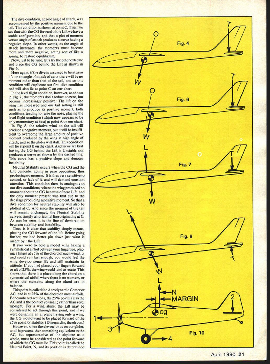
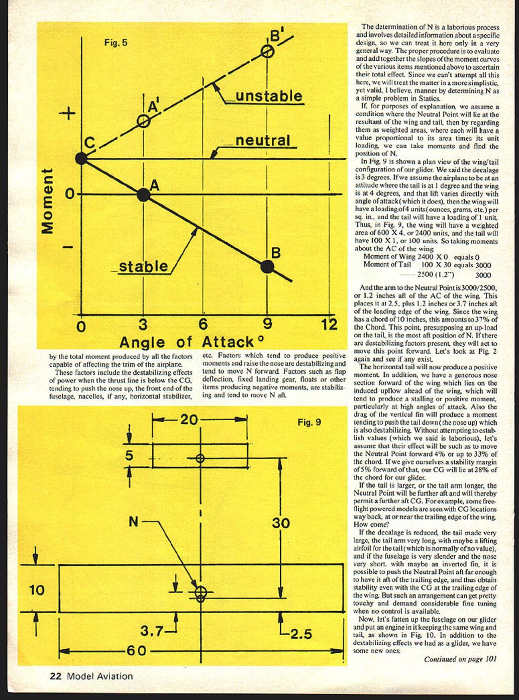
In a dive (slightly nose‑down), the wing may be at zero lift and produce no moment about the CG, while the tail still produces a positive moment tending to push the nose back up. Thus, with the CG forward of the lift, the arrangement is stable and a plot of moment versus angle of attack produces a curve with a negative slope: as angle of attack increases, the restoring moments become more negative, acting like a spring to restore equilibrium.
Now try placing the CG behind the lift. The dive condition at zero lift will be the same as before. But in level flight, the moments become increasingly positive: the wing lift and tail setting both tend to raise the nose, making level flight only momentary. At high angle of attack the tail's negative moment will be insufficient to overcome the wing's large positive moment, and the glider will stall. Thus, a CG behind the lift is unstable and produces a curve with positive slope, denoting instability.
Neutral stability occurs when the CG and the lift coincide, producing no net moment. It is very sensitive to control and will demand constant attention. Graphically, the neutral stability curve is a horizontal line originating at the dive condition point and serving as the demarcation between stability and instability.
Thus, stability simply means placing the CG forward of the lift. Before going further, we should pin down what is meant by "the lift."
If you hold a model wing having a symmetrical airfoil between your fingertips at 25% of the chord at each wing tip and run fast enough, you will feel the wing develop some lift and still maintain attitude. If your fingers were forward or aft of 25% the wing would tend to rotate. This shows there is a place along the chord on a symmetrical airfoil where there is no moment — the aerodynamic center (AC) — and it is at 25% of the chord on most airfoils. For cambered sections, the 25% point is also the AC and is the point of constant, rather than zero, moment. For a wing alone, the lift may be considered to act through this point, and if designing an airplane with only a wing, the CG would want to be placed forward of the 25% point for stability (disregarding elevator effects).
However, when an elevator or tail is present, something equivalent to the AC but representative of the airplane as a whole must be considered. This point is called the neutral point, N, and its position is determined by the combined effects of wing, tail, and other components.
Determining N is a laborious process involving detailed design data. The proper procedure evaluates and adds the slopes of the moment curves of the various components to ascertain their total effect. Here we treat the matter in a simplified, yet valid, manner by determining N as a statics problem.
Assume the neutral point lies at the resultant of wing and tail. Regard them as weighted areas, each proportional to its area times its unit loading, then take moments to find N.
In Fig. 9 a plan view of the wing/tail configuration of our glider is shown. Assume decalage is 3 degrees. If the airplane attitude is such that the tail is at 1 degree and the wing at 4 degrees, and lift varies directly with angle of attack, then the wing will have a loading of 4 units per sq. in. and the tail 1 unit. If the wing area is 600 sq. in. and the tail is 100 sq. in., then:
- Wing weighted area = 600 × 4 = 2400 units
- Tail weighted area = 100 × 1 = 100 units
Taking moments about the wing AC:
- Moment of wing = 2400 × 0 = 0
- Moment of tail = 100 × 30 = 3000
The arm to the neutral point is 3000 / (2400 + 100) = 3000 / 2500 = 1.2 inches aft of the wing AC. If the wing AC is at 2.5 inches aft of the leading edge, this places N at 2.5 + 1.2 = 3.7 inches aft of the leading edge. With a chord of 10 inches, this is 37% of the chord. This point, presupposing an up‑load on the tail, is the most aft position of N. Destabilizing factors will move this point forward.
Looking back at Fig. 2, destabilizing effects include:
- A horizontal tail producing a positive moment (up‑load).
- A generous nose section that lies in the induced upflow ahead of the wing, producing a stalling (positive) moment, particularly at high angles of attack.
- Drag of the vertical fin producing a moment that pushes the tail down (nose up).
Without detailed values, we can simply say their effect might move the neutral point forward about 4%, to roughly 33% of the chord. If we give ourselves a stability margin of 5% forward of that, the CG will lie at 28% of the chord for our glider.
If the tail is larger or the tail arm longer, the neutral point moves aft and permits a further aft CG. Some free‑flight powered models exhibit CG locations way back, at or near the trailing edge. This is possible if decalage is reduced, the tail is very large with a long arm, the tail has a lifting airfoil, the fuselage is slender and the nose short, and perhaps an inverted fin is used. Such arrangements can be touchy and demand fine tuning when no control is available.
Now, if we fatten the fuselage and add an engine while keeping the same wing and tail (Fig. 10), additional destabilizing effects appear.
About the CG / Powers
Continued from page 22
The new destabilizing and stabilizing effects include:
- The engine thrust line is below the CG and produces a nose‑up moment, which is destabilizing and tends to move N forward.
- The propeller slipstream increases downwash over the tail, loading it more and pushing the tail down (nose up), which is destabilizing and moves N forward.
- A fatter fuselage presents greater area into the upflow ahead of the wing (more instability); N moves forward again.
- The fixed landing gear is stabilizing. It tends to pull the nose down and cancels the effects of the other items to some extent.
The net result for most scale models of similar basic configuration is that the neutral point usually winds up at or very close to 30% of the chord of the wing. Thus a good, safe and comfortable CG location is about 5% forward of the 30% neutral point, or about 25% of the chord.
So now we understand why the CG is forward for beginners and can be further aft for experts. As a matter of fact, I have several models all balanced at approximately 25%, and it pleases me to see them recover nicely from a stall and be generally forgiving of my control mistakes. Many fliers don't pay much attention to CG location. They just balance the airplane "about a third of the way back" and seem to do fine. This is not always because they are talented fliers; they may be struggling against some instability without realizing it.
The way to be sure is to test fly your model at varying CG positions:
- Move the CG forward a little at a time until it's hard to get the nose up enough to slow for landing.
- Then move the CG aft in small increments until it becomes sensitive and skittish.
- Ease back a little from both extremes and let these be your limits.
For beginners, a CG location of 25% of the chord is a good place to start.
We have been expressing the CG location as a percent of chord because we used a constant‑chord, rectangular wing in our example. Not all airplanes are made this way; some have tapered, elliptical, triangular wings or multiple wings. Then what is the chord?
In the next installment we will discuss the mean aerodynamic chord and how to find it for such configurations.
Questions and comments may be addressed to the author in care of the editor.
(To be continued.)
Brad Powers
Transcribed from original scans by AI. Minor OCR errors may remain.

