
Let's Talk About The CG
Last month the author discussed CG and its effect on stability. In this second of a three-part series he talks about Mean Aerodynamic Chord and how to find it on various configurations.
Brad Powers
In last month's issue we discussed the CG and its effect on stability. We determined that it must always lie forward of the neutral point — at about 25% of the chord for most conventional designs. The question then arose, "What, exactly, is meant by the chord?" For a rectangular planform, one having no taper, the chord is constant. But what about a tapered wing as on a Mustang, or the elliptical wing of a Spitfire, or the delta shape of a Mirage? What about flying saucers? And what about biplanes?
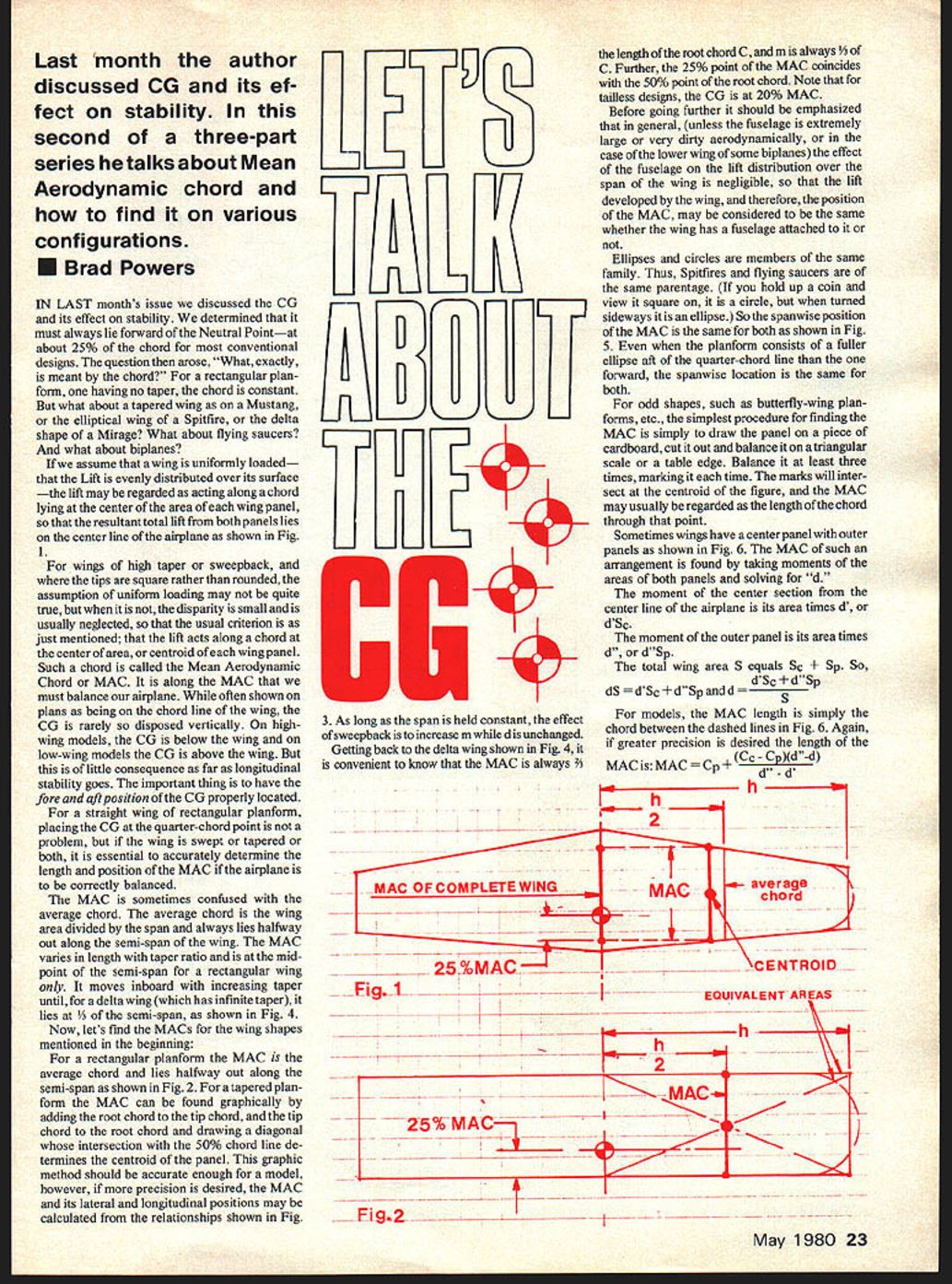
If we assume that a wing is uniformly loaded — that the lift is evenly distributed over its surface — the lift may be regarded as acting along a chord lying at the center of area of each wing panel, so that the resultant total lift from both panels lies on the center line of the airplane as shown in Fig. 1.
For wings of high taper or sweepback, and where the tips are square rather than rounded, the assumption of uniform loading may not be quite true, but when it is not, the disparity is small and is usually neglected. The usual criterion is as just mentioned: the lift acts along a chord at the center of area, or centroid, of each wing panel.
Such a chord is called the Mean Aerodynamic Chord or MAC. It is along the MAC that we must balance our airplane. While often shown on plans as being on the chord line of the wing, the CG is rarely so disposed vertically. On high-wing models, the CG is below the wing and on low-wing models the CG is above the wing. This is of little consequence as far as longitudinal stability goes. The important thing is to have the fore-and-aft position of the CG properly located.
For a straight wing of rectangular planform, placing the CG at the quarter-chord point is not a problem, but if the wing is swept or tapered or both, it is essential to accurately determine the length and position of the MAC if the airplane is to be correctly balanced.
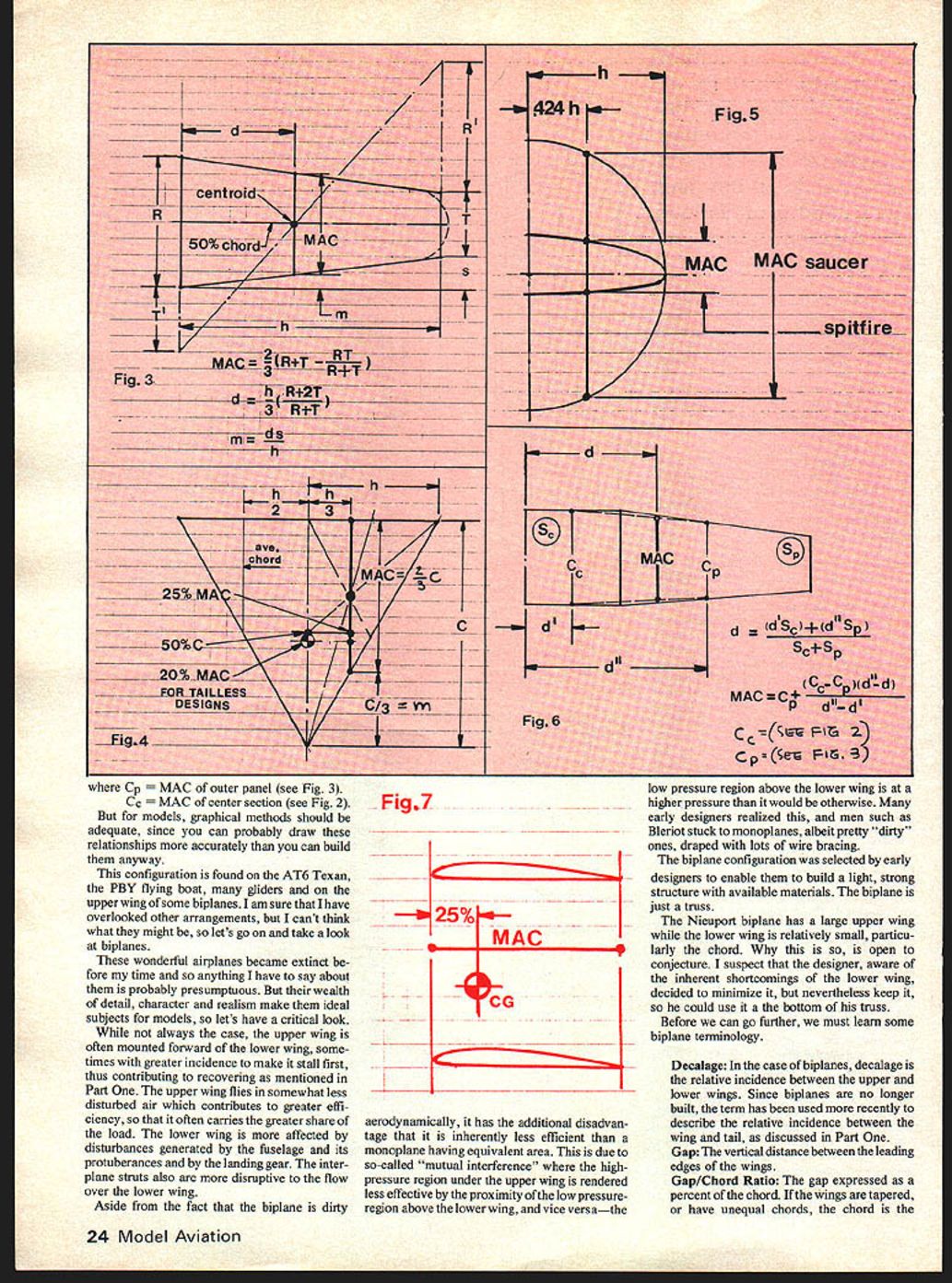
The MAC is sometimes confused with the average chord. The average chord is the area divided by the span and always lies halfway out along the semi-span as shown in Fig. 2. For a tapered planform the MAC can be found graphically by adding the root chord to the tip chord, and drawing a diagonal whose intersection with the 50% chord line determines the centroid of the panel. This graphic method should be accurate enough for a model; however, if more precision is desired, the MAC and its lateral and longitudinal positions may be calculated from the relationships shown in Fig. 3.
As long as the span is held constant, the effect of sweepback is to increase m while d is unchanged.
Getting back to the delta wing shown in Fig. 4, it is convenient to know that the MAC is always 3/4 the length of the root chord C, and m is always 1/3 of C. Further, the 25% point of the MAC coincides with the 50% point of the root chord. Note that for tailless designs, the CG is at 20% MAC.
Before going further it should be emphasized that in general (unless the fuselage is extremely large or very dirty aerodynamically, or in the case of the lower wing of some biplanes) the effect of the fuselage on the lift distribution over the span of the wing is negligible, so that the lift developed by the wing, and therefore the position of the MAC, may be considered to be the same whether the wing has a fuselage attached to it or not.
Ellipses and circles are members of the same family. Thus, Spitfires and flying saucers are of the same parentage. (If you hold up a coin and view it square on, it is a circle, but when turned sideways it is an ellipse.) So the spanwise position of the MAC is the same for both as shown in Fig. 5. Even when the planform consists of a fuller ellipse aft of the quarter-chord line than the one forward, the spanwise location is the same for both.
For odd shapes, such as butterfly-wing planforms, etc., the simplest procedure for finding the MAC is to draw the panel on a piece of cardboard, cut it out and balance it on a triangular scale or a table edge. Balance it at least three times, marking it each time. The marks will intersect at the centroid of the figure, and the MAC may usually be regarded as the length of the chord through that point.
Sometimes wings have a center panel with outer panels as shown in Fig. 6. The MAC of such an arrangement is found by taking moments of the areas of both panels and solving for d.
- The moment of the center section from the center line of the airplane is its area times d', or d'·Sc.
- The moment of the outer panel is its area times d", or d"·Sp.
- The total wing area S equals Sc + Sp.
So, dS = d'·Sc + d"·Sp and d = (d'·Sc + d"·Sp)/S.
For models, the MAC length is simply the chord between the dashed lines in Fig. 6. Again, if greater precision is desired the length of the MAC is:
MAC = Cp + (Cc - Cp)(d'/d)
where Cp = MAC of outer panel (see Fig. 3) and Cc = MAC of center section (see Fig. 2).
But for models, graphical methods should be adequate, since you can probably draw these relationships more accurately than you can build them anyway.
This configuration is found on the AT-6 Texan, the PBY flying boat, many gliders and on the upper wing of some biplanes. I am sure that I have overlooked other arrangements, but I can't think what they might be, so let's go on and take a look at biplanes.
These wonderful airplanes became extinct before my time and so anything I have to say about them is probably presumptuous. But their wealth of detail, character and realism make them ideal subjects for models, so let's have a critical look.
While not always the case, the upper wing is often mounted forward of the lower wing, sometimes with greater incidence to make it stall first, thus contributing to recovery as mentioned in Part One. The upper wing lies in somewhat less disturbed air which contributes to greater efficiency, so that it often carries the greater share of the load. The lower wing is more affected by disturbances generated by the fuselage and its protuberances and by the landing gear. The interplane struts also are more disruptive to the flow over the lower wing.
Aside from the fact that the biplane is dirty aerodynamically, it has the additional disadvantage that it is inherently less efficient than a monoplane having equivalent area. This is due to the so-called "mutual interference" where the high-pressure region under the upper wing is rendered less effective by the proximity of the low-pressure region above the lower wing, and vice versa — the low-pressure region above the lower wing is at a higher pressure than it would be otherwise. Many early designers realized this, and men such as Blériot stuck to monoplanes, albeit pretty "dirty" ones, draped with lots of wire bracing.
The biplane configuration was selected by early designers to enable them to build a light, strong structure with available materials. The biplane is just a truss.
The Nieuport biplane has a large upper wing while the lower wing is relatively small, particularly in chord. Why this is so is open to conjecture. I suspect that the designer, aware of the inherent shortcomings of the lower wing, decided to minimize it, but nevertheless keep it, so he could use it as the bottom of his truss.
Before we can go further, we must learn some biplane terminology.
Decalage
Decalage: In the case of biplanes, decalage is the relative incidence between the upper and lower wings. Since biplanes are no longer built, the term has been used more recently to describe the relative incidence between the wing and tail, as discussed in Part One.
Gap
Gap: The vertical distance between the leading edges of the wings.
Gap/Chord Ratio
Gap/Chord Ratio: The gap expressed as a percent of the chord. If the wings are tapered, or have unequal chords, the chord used is the MAC of the pair.
Stagger
Stagger: The positioning of one wing forward of the other. If the upper wing is forward of the lower wing, the stagger is positive. If the lower wing is forward, as on the Beechcraft Staggerwing, the stagger is negative.
Fig. 7 shows the simplest case where there is no stagger, no decalage, and the wings are of equal area. The MAC is, therefore, equal to the chord of either of the wings and lies vertically halfway between them if the loading on each wing is the same. However, as we mentioned earlier, the upper wing will carry a larger share of the load and the vertical position of the MAC will be somewhat closer to the upper wing. Since there is no stagger, the fore-and-aft position will be the same as that of the wings themselves, and the CG location will not be affected by the vertical position of the MAC.
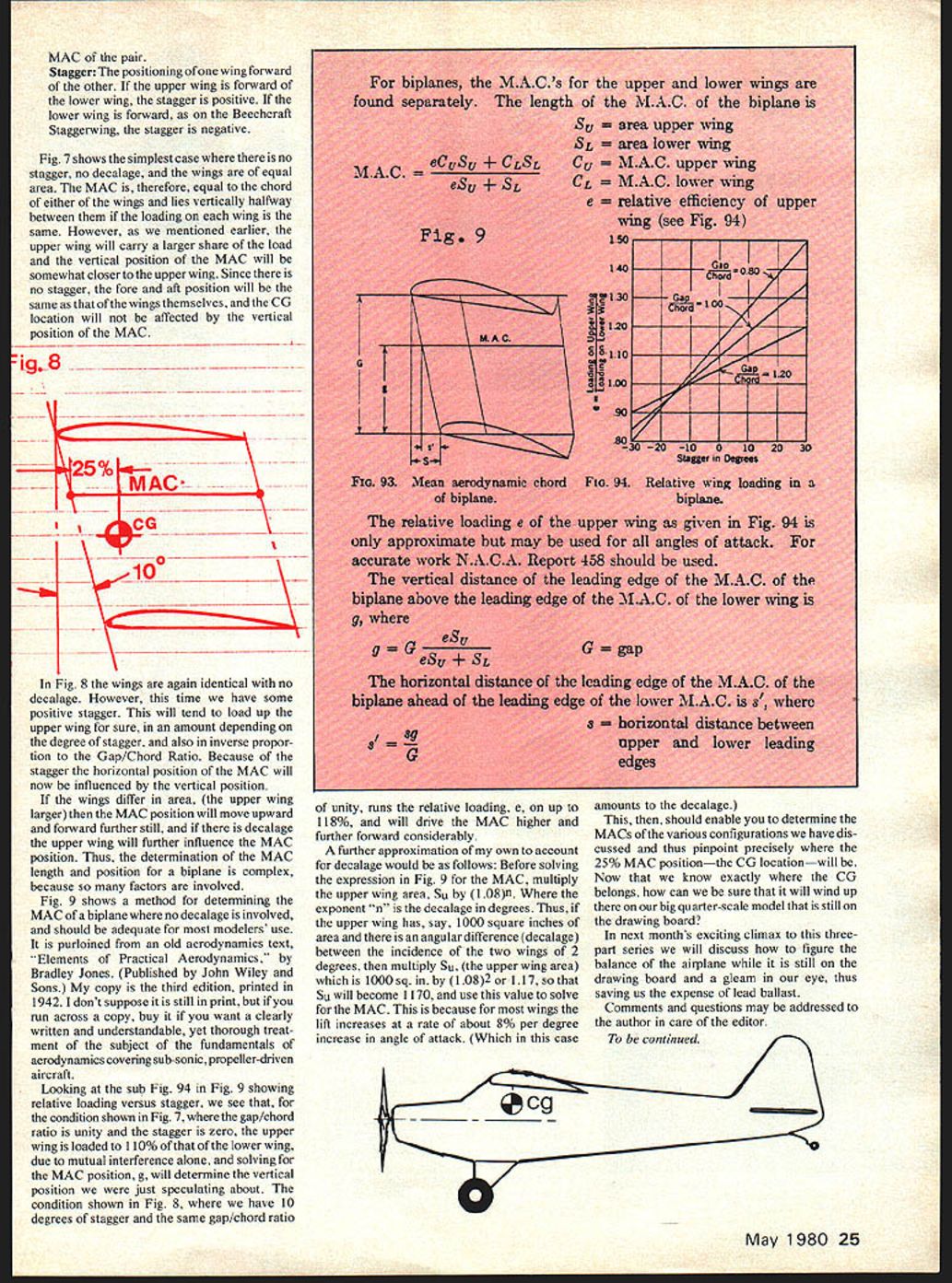
In Fig. 8 the wings are again identical with no decalage. However, this time we have some positive stagger. This will tend to load up the upper wing for sure, in an amount depending on the degree of stagger, and also in inverse proportion to the Gap/Chord Ratio. Because of the stagger the horizontal position of the MAC will now be influenced by the vertical position.
If the wings differ in area (the upper wing larger) then the MAC position will move upward and forward further still, and if there is decalage the upper wing will further influence the MAC position. Thus, the determination of the MAC length and position for a biplane is complex, because so many factors are involved.
Fig. 9 shows a method for determining the MAC of a biplane where no decalage is involved, and should be adequate for most modelers' use. It is purloined from an old aerodynamics text, "Elements of Practical Aerodynamics," by Bradley Jones (Published by John Wiley and Sons). My copy is the third edition, printed in 1942. I don't suppose it is still in print, but if you run across a copy, buy it if you want a clearly written and understandable, yet thorough treatment of the fundamentals of aerodynamics covering subsonic, propeller-driven aircraft.
Looking at sub-Fig. 9A in Fig. 9 showing relative loading versus stagger, we see that for the condition shown in Fig. 7, where the gap/chord ratio is unity and the stagger is zero, the upper wing is loaded to 110% of that of the lower wing, due to mutual interference alone, and solving for the MAC position, g, will determine the vertical position we were just speculating about. The condition shown in Fig. 8, where we have 10 degrees of stagger and the same gap/chord ratio of unity, runs the relative loading, e, up to 118%, and will drive the MAC higher and further forward considerably.
A further approximation of my own to account for decalage would be as follows: before solving the expression in Fig. 9 for the MAC, multiply the upper wing area, Su, by (1.08)^n, where the exponent n is the decalage in degrees. Thus, if the upper wing has, say, 1,000 square inches of area and there is an angular difference (decalage) between the incidences of the two wings of 2 degrees, then multiply Su (1,000 sq. in.) by (1.08)^2 ≈ 1.17, so that Su will become 1,170, and use this value to solve for the MAC. This is because for most wings the lift increases at a rate of about 8% per degree increase in angle of attack (which in this case amounts to the decalage).
This, then, should enable you to determine the MACs of the various configurations we have discussed and thus pinpoint precisely where the 25% MAC position — the CG location — will be. Now that we know exactly where the CG belongs, how can we be sure that it will wind up there on our big quarter-scale model that is still on the drawing board?
In next month's exciting climax to this three-part series we will discuss how to figure the balance of the airplane while it is still on the drawing board and a gleam in our eye, thus saving us the expense of lead ballast.
Comments and questions may be addressed to the author in care of the editor.
To be continued.
Transcribed from original scans by AI. Minor OCR errors may remain.

