
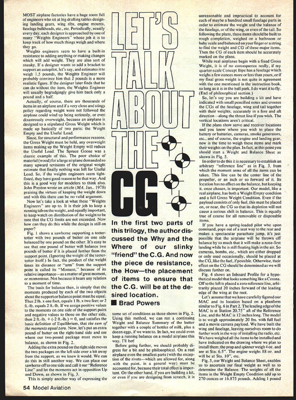
Let's Talk About The CG
Most airplane factories have a huge room full of engineers who sit at big drafting tables designing landing gears, wing ribs, engine mounts, fuselage bulkheads, etc. Periodically, usually every day, each designer is approached by one of many "weights engineers" whose job it is to keep track of how much things weigh and where they go.
Weights engineers seem to have a built-in resistance to adding anything or making changes that will add weight. They are also sort of sneaky. If a designer wants to add a bracket to support an autopilot, say, and estimates it to weigh 1.5 pounds, the weights engineer will probably convince him that 2 pounds is a more realistic figure. If the designer later finds that he can do without the item, the weights engineer will usually begrudgingly give him back only a pound and a half.
Actually, of course, there are thousands of items in an airplane and if a very close and stingy policy regarding weight were not followed the airplane could wind up seriously, or even disastrously, overweight. An airplane is designed to a stipulated gross weight which is made up basically of two parts: the weight empty and the useful load.
Since, for structural and performance reasons, the gross weight must be held, any overweight items making up the weight empty will reduce the useful load. The Spruce Goose was a classic example. The poor choice of material (wood) for a large airplane demanded so many upward revisions of the original weight estimate that finally nothing was left for useful load. So, if the weights engineers seem tightfisted, they have good reason to be. Modelers should use the same mindset. John Preston wrote an article praising the virtues of keeping the weight down, and with this there can be no valid argument.
What the Weights Engineers Do
It is the weights engineer's job to keep a running tab on the weight and, equally important, to keep watch on distribution of the weight to be sure that the center of gravity (CG) limits are not exceeded. How can they do this while the design is still on paper?
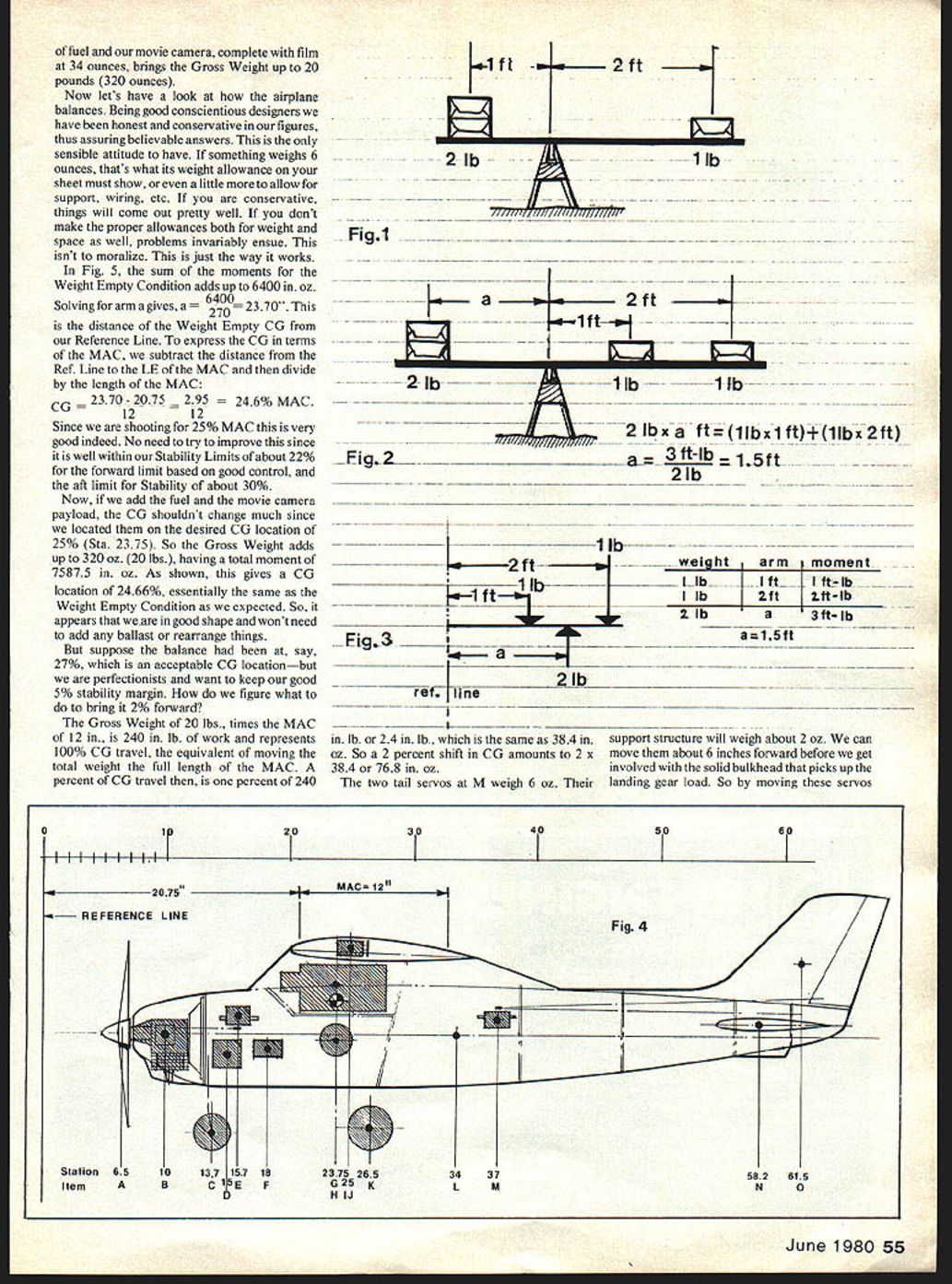
Figure 1 shows a sawhorse supporting a teeter-totter with two pounds of butter on one side balanced by one pound on the other. It's easy to see that one pound of butter will balance two pounds of butter if it is placed farther from the support point (ignoring the weight of the teeter-totter itself). In fact, the product of the weight times its distance or "arm" from the support point is called its "moment" — because of its relative importance, as a matter of great moment or momentousness — not because it bears any relation to a moment of time.
The basis for balance then is simply that the moments produced by each of the two objects about the support or balance point must be equal. Thus 2 lb × 1 ft equals 1 lb × 2 ft; or 2 ft-lb equals 2 ft-lb. If we assign positive values to the moments on one side of the support point and negative values to those on the other side, then 2 ft-lb + (−2 ft-lb) = 0, which satisfies the basic definition of equilibrium: the sum of the moments equals zero.
If we add an extra pound of butter on one side, the two-pound package on the other side must move out to restore balance. We can also place our sawhorse off to one side and call it a "reference line" and let the moments act in opposition up and down — another way of expressing the same set of conditions.
Using this method we can run a continuing weight-and-balance summary of the butter together with a couple of bottles of milk and a dozen eggs if we want to. In fact, we could even keep a running balance on a model airplane this way.
Practical Philosophy for Modelers
On a real airplane even the smallest parts (with the exception of rivets — which are allowed for, along with paint, in a general way) must be accounted for because their total effect is important. On the other hand, if you are building a kit, or even designing from scratch, it is unreasonable and impractical to account for each of maybe a hundred small fuselage parts to estimate the weight and balance of the fuselage, wing, or tail. So, build these items to rough completion, weigh them on a bathroom or baby scale, and balance them on your finger or a string to find the weight and CG of these major items. Then mark the CG of each item accurately on the plans.
While real airplanes begin with a fixed gross weight, it is of little consequence if my quarter-scale Concept Bipe has a fuselage that weighs a few ounces more or less than yours, or if my final gross weight is not exactly the same as the one in the instruction book, so long as it is in the ballpark. I do want it to fly.
So, suppose you are building a kit and have marked with small penciled notes the CGs of the fuselage, wing, and tail together with their weights, accurately in a fore-and-aft direction — along the thrust line if you wish. The vertical locations aren't critical.
If the plans show servo and receiver locations and you know where you wish to place the battery or batteries, camera, smoke generator, etc., and of course the engine and landing gear, now is the time to weigh these items and mark their weights on the plan. At this point you should start a weight-and-balance sheet.
Reference Line and Balance Practice
To do this it is necessary to establish an arbitrary reference line from which the moment arms of all items can be taken. This line can be the centerline of the propeller, or an inch or so forward of it. Its location has no effect on the actual balance, but once chosen it should be kept.
Our model, like a real airplane, has both a weight-empty condition and a full gross-weight condition. Even if the payload consists of only fuel, this must be placed on or near the CG so that its depletion will not cause a serious shift in balance. This is equally true for all removable or disposable items.
If you have a spring-loaded pilot who, upon command, pops out of a seat and makes a spectacular parachute jump, it's possible the airplane will be thrown off balance so much that it will make a nose-first landing while he is still floating. Cameras, bombs, etc., which are either dropped or only used occasionally, should be placed at the CG like the fuel if possible. Otherwise, their effect on the CG should be determined.
Example: Hypothetical Cessna-like Model
Figure 4 shows an inboard profile for a hypothetical model that looks something like a Cessna. Off to the left is placed a zero reference line, arbitrarily 20 inches forward of the leading edge of the wing at the root.
Assume we have carefully figured our MAC and its location based on a planform. The leading edge of the MAC is at station 20.75" aft of the reference line, and the MAC is 12 inches long. The model is to weigh approximately 20 lb with full fuel and a movie camera payload. We have built the wing and fuselage, leaving room to install the radio, etc. We have weighed all the items to be installed and have indicated on the drawing where we plan to install them: the prop and spinner weigh 4 oz and are at Sta. 6.5"; the engine weighs 88 oz and will be at Sta. 10".
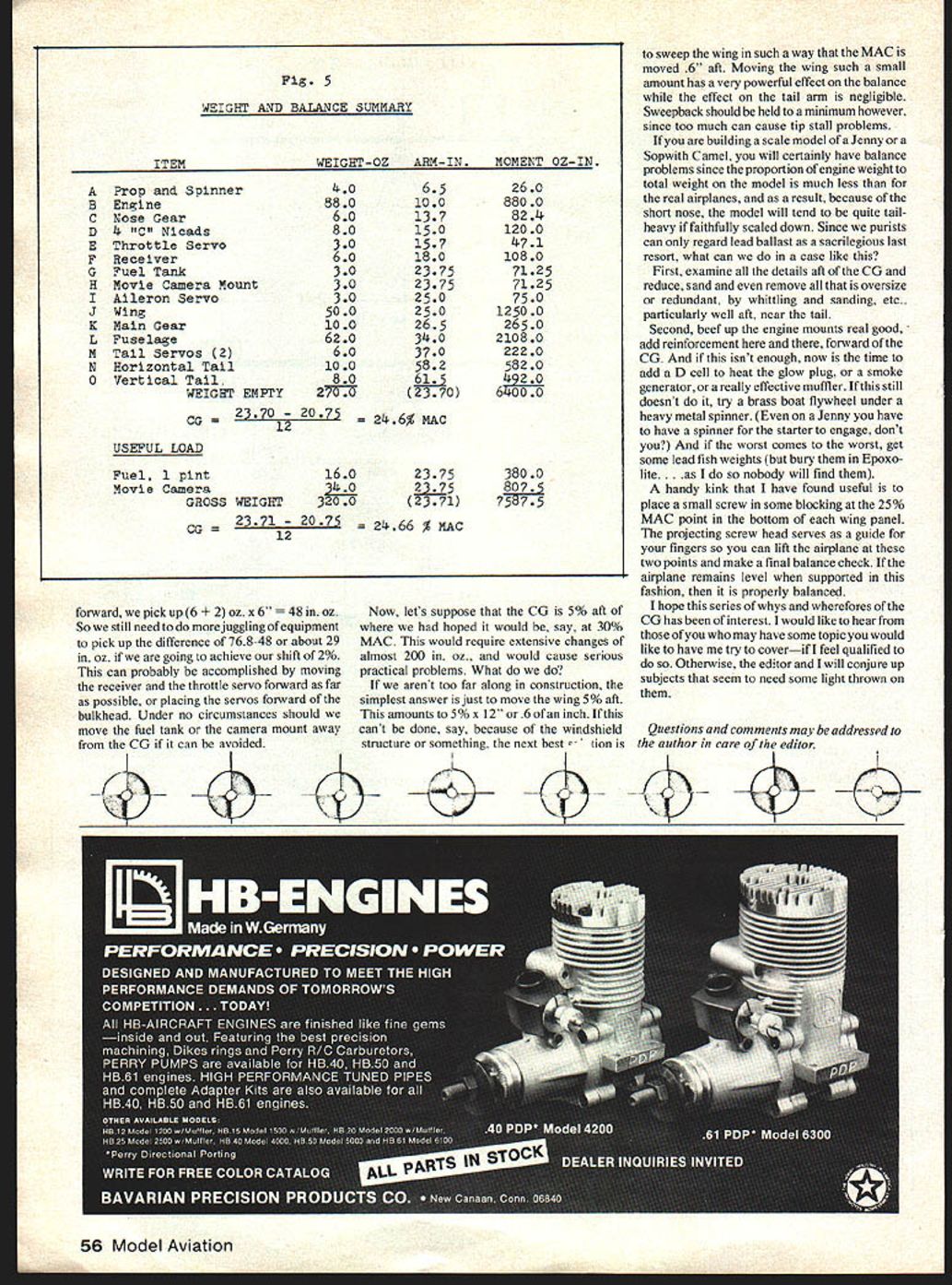
Figure 5, our weight-and-balance sheet, enables us to ascertain final weight as well as to determine the balance. The weights of all the items in the weight-empty condition add up to 270 oz (16.875 lb). Adding 1 lb of fuel (16 oz) and our movie camera, complete with film, at 34 oz brings the gross weight up to 20 lb (320 oz).
Being honest and conservative in our figures assures believable answers. If something weighs 6 oz, that's what its allowance on your sheet must show, or even a little more to allow for support, wiring, etc. If you are conservative, things will come out pretty well. If you don't make the proper allowances for weight and space, problems invariably ensue.
Weight and Balance Summary
ITEM WEIGHT (oz) ARM (in) MOMENT (oz·in)
- A Prop and Spinner 4.0 6.5 26.0
- B Engine 88.0 10.0 880.0
- C Nose Gear 6.0 13.7 82.4
- D 4 "C" NiCads 8.0 15.0 120.0
- E Throttle Servo 3.0 15.7 47.1
- F Receiver 6.0 18.0 108.0
- G Fuel Tank 16.0 23.75 380.0
- H Movie Camera Mount 34.0 23.75 807.5
- I Aileron Servo 3.0 25.0 75.0
- J Wing 50.0 25.0 1250.0
- K Main Gear 10.0 26.0 260.0
- L Fuselage 62.0 34.0 2108.0
- M Tail Servos (2) 6.0 37.0 222.0
- N Horizontal Tail 10.0 58.2 582.0
- O Vertical Tail 8.0 61.5 492.0
WEIGHT EMPTY: 270.0 oz — total moment = 6400.0 oz·in Weight-empty CG (in from reference line): a = 6400 / 270 = 23.70"
CG in terms of MAC: CG = (23.70 − 20.75) / 12 = 2.95 / 12 = 24.6% MAC
USEFUL LOAD:
- Fuel, 1 pint 16.0 oz 23.75 in 380.0 oz·in
- Movie Camera 34.0 oz 23.75 in 807.5 oz·in
GROSS WEIGHT: 320.0 oz — total moment = 7587.5 oz·in Gross-weight CG: (23.71 − 20.75) / 12 = 24.66% MAC
We are shooting for 25% MAC, so these results are very good. They fall well within stability limits of about 22% forward (good control) and about 30% aft (stability).
How to Move the CG
Suppose the balance had been at 27% (acceptable), but we want to bring it 2% forward to maintain a desirable 5% stability margin. How do we figure what to do?
The gross weight of 20 lb × MAC of 12 in = 240 in·lb of work and represents 100% CG travel (moving the total weight the full MAC length). One percent of CG travel is 1% of 240 in·lb = 2.4 in·lb = 38.4 in·oz. So a 2% shift in CG amounts to 2 × 38.4 = 76.8 in·oz.
The two tail servos at M weigh 6 oz; their support structure will weigh about 2 oz. If we can move them about 6 inches forward before hitting the bulkhead, moving these servos forward gains (6 + 2) oz × 6" = 48 in·oz. We would still need about 76.8 − 48 = 28.8 in·oz more. This can probably be accomplished by moving the receiver and throttle servo forward as far as possible, or placing servos forward of the bulkhead. Under no circumstances should we move the fuel tank or camera mount away from the CG if it can be avoided.
Now suppose the CG is 5% aft of where we want it, say at 30% MAC. This would require almost 200 in·oz of change and pose serious practical problems. Options:
- If you aren't too far along in construction, move the wing 5% aft (5% × 12" = 6 in).
- If the wing cannot be moved that far (windshield structure or other reasons), sweep the wing to move the MAC aft by the required amount (for example, 0.6"). A small change in sweep has a powerful effect on balance while having negligible effect on the tail arm. Keep sweepback to a minimum to avoid tip-stall problems.
Solutions for Tail-Heavy Scale Models
If you are building a scale model of a Jenny or Sopwith Camel you may have balance problems because the proportion of engine weight to total weight on the model is much less than on the real airplane; with a short nose the model will tend to be tail-heavy if faithfully scaled down. Purists regard lead ballast as a last resort. Alternatives:
- Examine all details aft of the CG and reduce, sand, or remove anything oversize or redundant — especially near the tail.
- Beef up the engine mounts and add reinforcement forward of the CG.
- Add useful forward items: a D cell to heat the glow plug, a smoke generator, or a heavy muffler.
- If necessary, fit a brass boat flywheel under a heavy metal spinner.
- If worst comes to worst, use lead fish weights (but encapsulate them in epoxy so they remain concealed and fixed).
A handy trick: place a small screw in blocking at the 25% MAC point in the bottom of each wing panel. The projecting screw head serves as a guide for your fingers so you can lift the airplane at these two points and make a final balance check. If the airplane remains level when supported this way, it is properly balanced.
I hope this series of whys and wherefores of the CG has been of interest. I would like to hear from readers who have topics they would like covered. Questions and comments may be addressed to the author in care of the editor.
Transcribed from original scans by AI. Minor OCR errors may remain.

