
Let's Talk About Float Design
Brad Powers
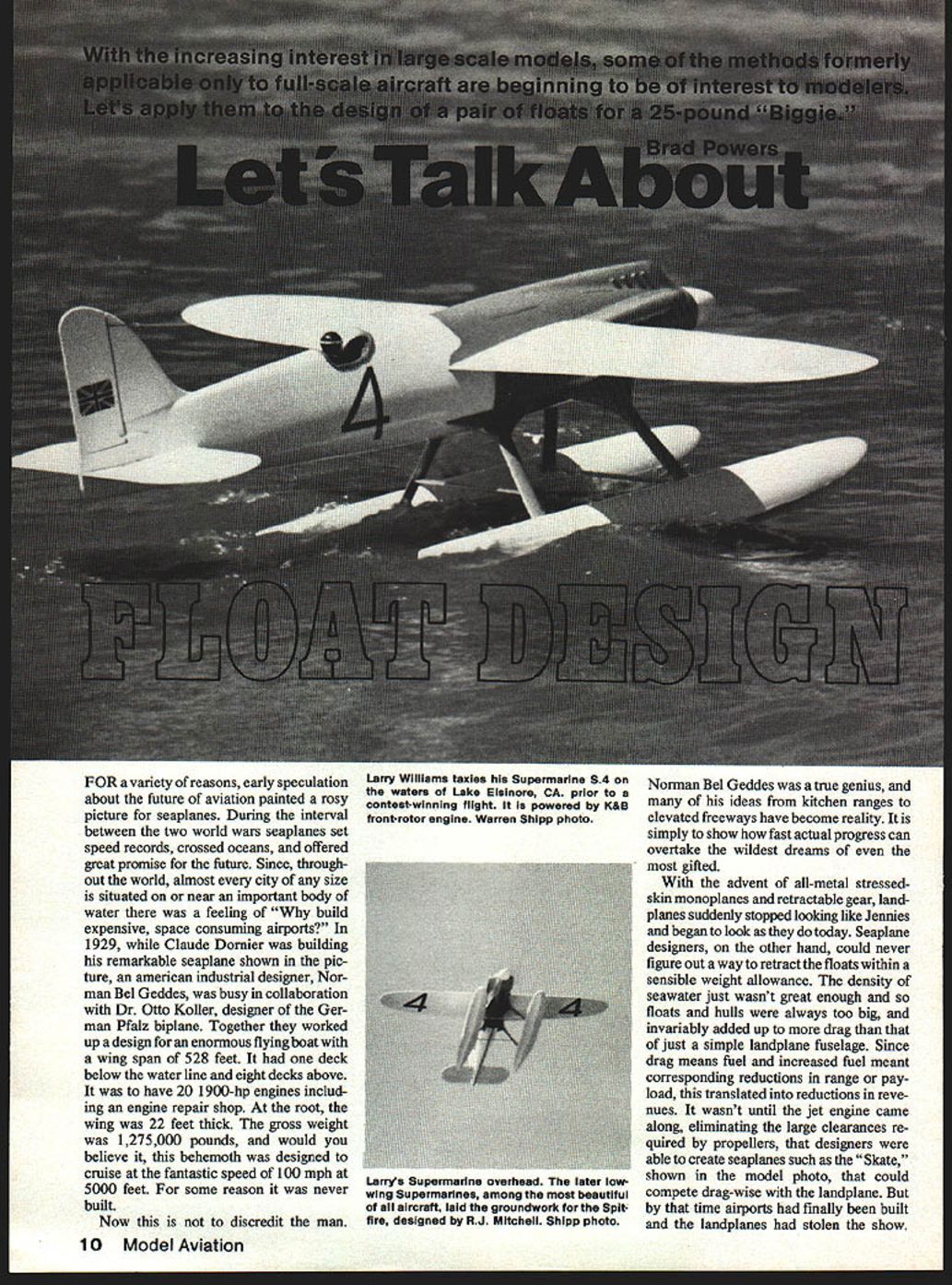
With the increasing interest in large-scale models, some of the methods formerly applicable only to full-scale aircraft are beginning to be of interest to modelers. Let's apply them to the design of a pair of floats for a 25-pound "Biggie."
For a variety of reasons, early speculation about the future of aviation painted a rosy picture for seaplanes. During the interval between the two world wars seaplanes set speed records, crossed oceans, and offered great promise for the future. Since, throughout the world, almost every city of any size is situated on or near an important body of water there was a feeling of "Why build expensive, space-consuming airports?" In 1929, while Claude Dornier was building his remarkable seaplane, an American industrial designer, Norman Bel Geddes, in collaboration with Dr. Otto Koller (designer of the German Pfalz biplane), worked up a design for an enormous flying boat with a wingspan of 528 feet. It had one deck below the waterline and eight decks above, 20 × 1,900-hp engines (including an engine repair shop), a root wing thickness of 22 feet, and a gross weight of 1,275,000 pounds. It was designed to cruise at 100 mph at 5,000 feet. For some reason it was never built.
Norman Bel Geddes was a true genius, and many of his ideas have become reality. The point is how fast actual progress can overtake the wildest dreams of even the most gifted.
With the advent of all-metal stressed-skin monoplanes and retractable gear, landplanes changed dramatically. Seaplane designers could never find a way to retract floats within a sensible weight allowance. Floats and hulls added drag compared with a simple landplane fuselage, and that drag meant more fuel and reduced range or payload. It wasn't until the jet engine removed large propeller-clearance constraints that designers could create seaplanes with competitive drag characteristics. By that time, airports had been built and landplanes had largely stolen the show.
Other factors also determined the decline of seaplanes:
- Rough seas and non-calm landing areas.
- Congested or unsafe operating areas.
- Handling, mooring, and maintenance difficulties.
- Severe corrosive effects of seawater on aluminum-alloy hulls.
Numerous approaches to operating aircraft on water have been developed, including various float shapes, skis, hydrofoils, large hulls stabilized by tip floats, sponsons, and blended hull-wing configurations. With the advent of the ducted fan, hydrofoils and blended hull-wing ideas become more attractive for models since propeller-clearance problems are reduced. But this article concentrates on principles underlying simple, scale-type floats appropriate to scale models and uses procedures to evaluate a model-type float developed by Irwin Ohlsson.
A float is more than functional sculpture; it must:
- Provide adequate buoyancy at rest.
- Provide minimum resistance to motion through the water during takeoff progress.
- Provide smooth, stable variations of trim during takeoff and landing (the pilot has little or no control over trim attitude at low water speeds).
- Provide a stable, reasonably soft landing entry course, with minimum weight and air drag.
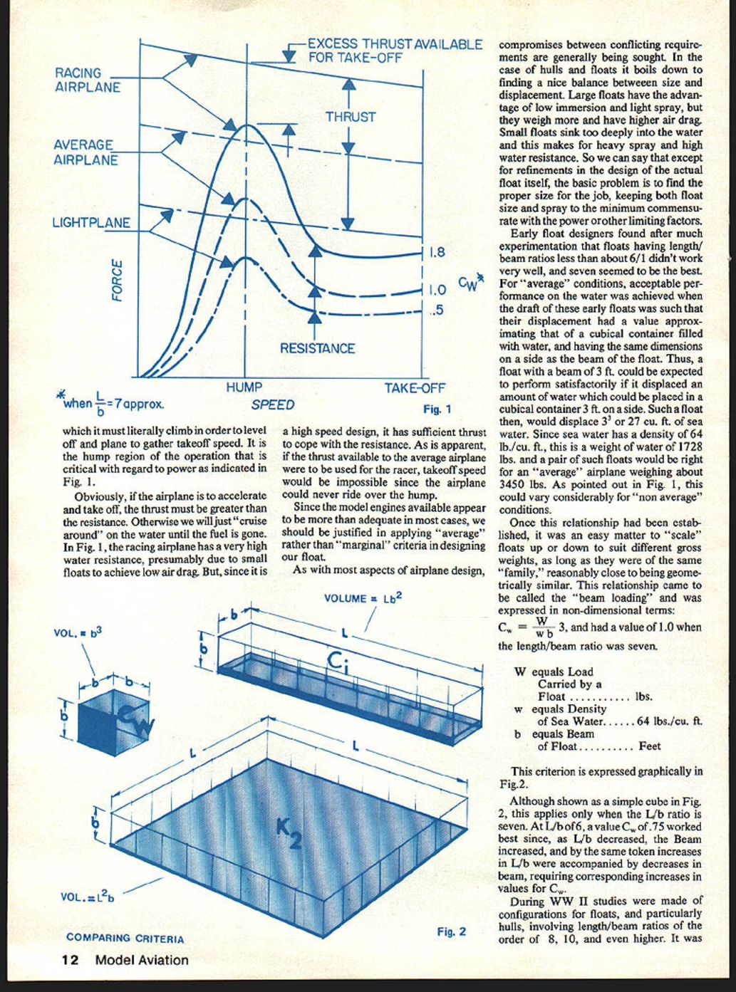
Those who have ridden on water skis, or aboard a speedboat or cruiser, are familiar with changing attitudes as the craft accelerates: the nose rises until, if sufficient power is available, it levels off and planes. An airplane on floats behaves similarly. As it moves forward it pushes a sizable volume of water ahead of itself, creating a large wave or "hump" over the bow of the float. The hump region is critical with regard to required power: thrust must exceed water resistance for the airplane to accelerate and take off; otherwise it will simply cruise on the water until fuel is exhausted.
Since model engines usually provide adequate power, it's reasonable to apply "average" rather than "marginal" criteria in designing floats.
As with most airplane design, hull and float design is a series of compromises. Large floats give low immersion and light spray but weigh more and have more air drag. Small floats sink deeper, causing heavy spray and high water resistance. The basic problem is to find the proper size that keeps float size and spray to a minimum while matching available power.
Early designers found that floats with length/beam (L/b) ratios less than about 6/1 performed poorly; 7/1 was optimal for many applications. For "average" conditions, acceptable performance occurred when float draft produced a displacement approximately equal to that of a cube of side equal to the float beam. For example, a float with a 3 ft beam displacing 3^3 = 27 cu ft of sea water (sea water ≈ 64 lb/cu ft) would carry about 1,728 lb; a pair of such floats would suit an airplane of about 3,450 lb.
This led to the non-dimensional "beam loading" criterion: Cw = W / (w b^3) where:
- W = load carried by a float (lb)
- w = density of sea water (≈ 64 lb/cu ft)
- b = beam of float (ft)
Cw ≈ 1.0 when L/b = 7.
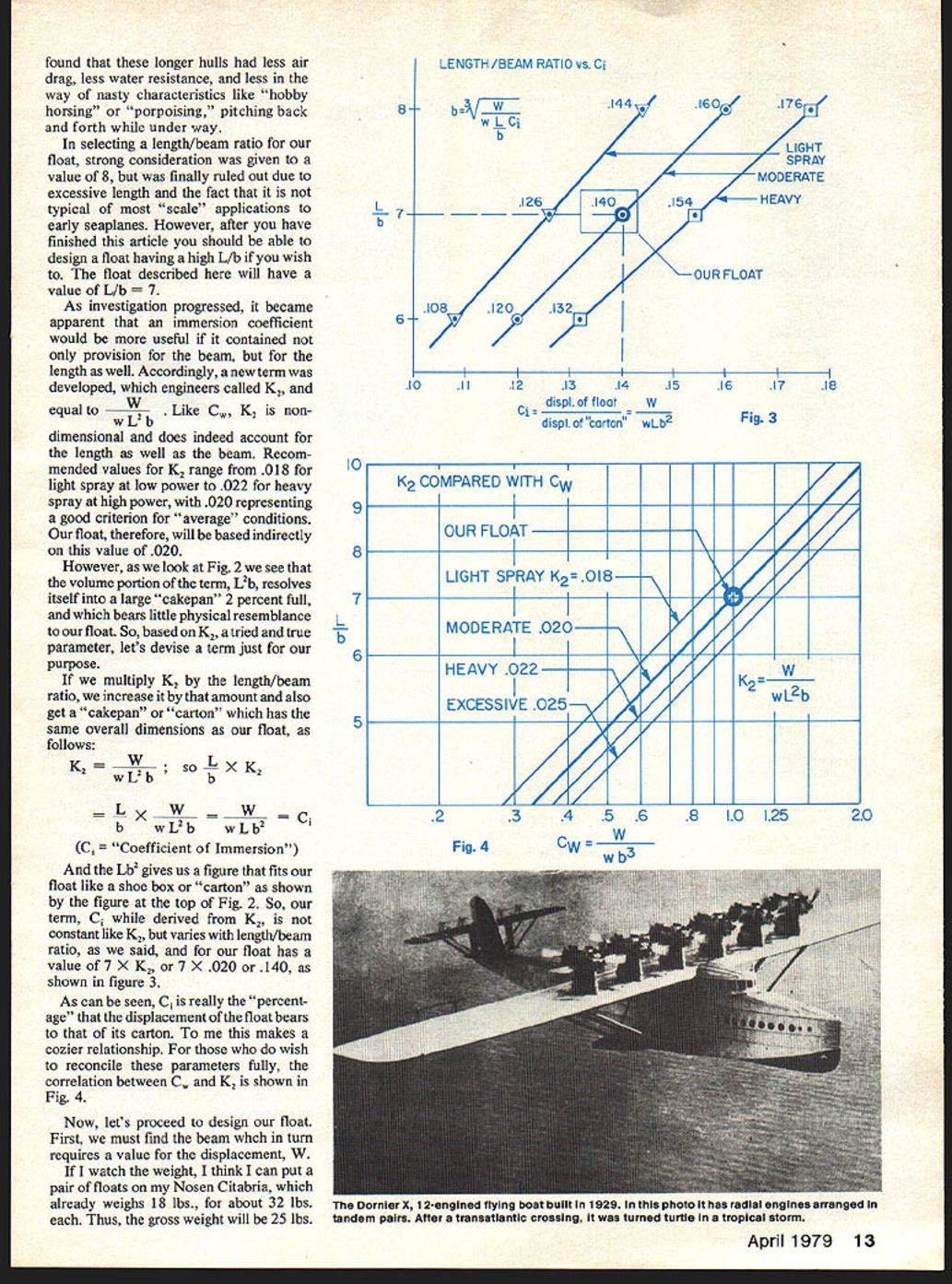
During WWII, studies explored longer hulls (L/b of 8, 10, even higher) and found these had less air drag, less water resistance, and fewer bad behaviors like hobby-horsing or porpoising. For scale applications a very long float can be impractical, so L/b = 7 is used in the example float here.
Because K2 (an immersion coefficient used by engineers) contains length as well as beam, it is defined: K2 = W / (w L^2 b) Recommended K2 values range from 0.018 (light spray, low power) to 0.022 (heavy spray, high power), with 0.020 as an average guideline.
To make a parameter that better resembles the float "carton" dimensions, multiply K2 by the length/beam ratio: Ci = L/b × K2 = W / (w L b^3) (Ci is the "Coefficient of Immersion" and varies with L/b.) For L/b = 7 and K2 = 0.020, Ci = 7 × 0.020 = 0.140. Ci represents the percentage the float displacement bears to that of its carton.
Design example: a 25-lb gross airplane (Nosen Citabria model) where each float carries 12.5 lb.
- W = 12.5 lb (per float)
- Ci = 0.140
With L/b = 7, Ci = W / (w × 7 b^3), so b = ∛(W / (7 × w × Ci)) = ∛(12.5 / (7 × 64 × 0.140)) ≈ 0.584 ft ≈ 7 in. Length L = 7 × b = 49 in.
As a check, Ci = 0.140 means the float displaces about 14% of its carton volume; numeric checks in the original analysis showed consistency with the chosen draft.
If planning to add weight later (e.g., a 3-lb camera) or operating in fresh water (density ≈ 62.4 lb/cu ft), consider a lower Ci (e.g., 0.126). That would increase beam to ~7.25 in and length to ~50.75 in but increase float weight roughly 10%.
Float shape considerations
- A completely streamlined body partially immersed tends to "suck under" as speed and power increase — it deflects water upward and sinks deeper. This is why many displacement vessels have a fixed maximum speed.
- A flat or V-shaped bottom near the step lets the water depart cleanly at the step and allows the float to ride up and plane, deriving dynamic lift from deflected water (much like a wing deflects air downward).
- The forebody (with step/transom) performs most of the dynamic work; the afterbody supplies static buoyancy at rest.
- A generous step depth assures clean wake departure and helps avoid wake reattachment that can cause porpoising.
- Forebody lines should be sharp to minimize resistance. Deadrise (angle between keel and chine) should increase forward to sharpen entry and provide trim stability.
- A large forebody displacement is needed to counter the nose-down moment produced by initial takeoff power application. Insufficient forebody restoring moment can produce forebody porpoising.
- Landing angle should allow the step to contact at an angle near 90% of the wing stalling angle for the slowest possible landing speed. The example float uses a landing angle of 9°, combined with 3° wing incidence for a total approx. of 12° landing attitude.
Other practical notes
- Flare at the chine directs spray and helps control it. Spray dams or blinders (metal strips flush with sides projecting about 1/2" below chine) reduce spray, but excessive size or forward placement may destabilize flight.
- Floats are destabilizing in flight; increase fin area to compensate and provide elevator trim (preferably an adjustable horizontal stabilizer).
- Do NOT toe-in floats; mount them firmly and accurately. Water forces are high and unforgiving.
- The afterbody should taper to a flat transom large enough for water-rudder mounts and internal pushrod outlets.
- Fit a water rudder on each float; pivot line about 25–30% of its chord. Area is not critical—use proportions suitable to float size.
Ohlsson's Widgeon
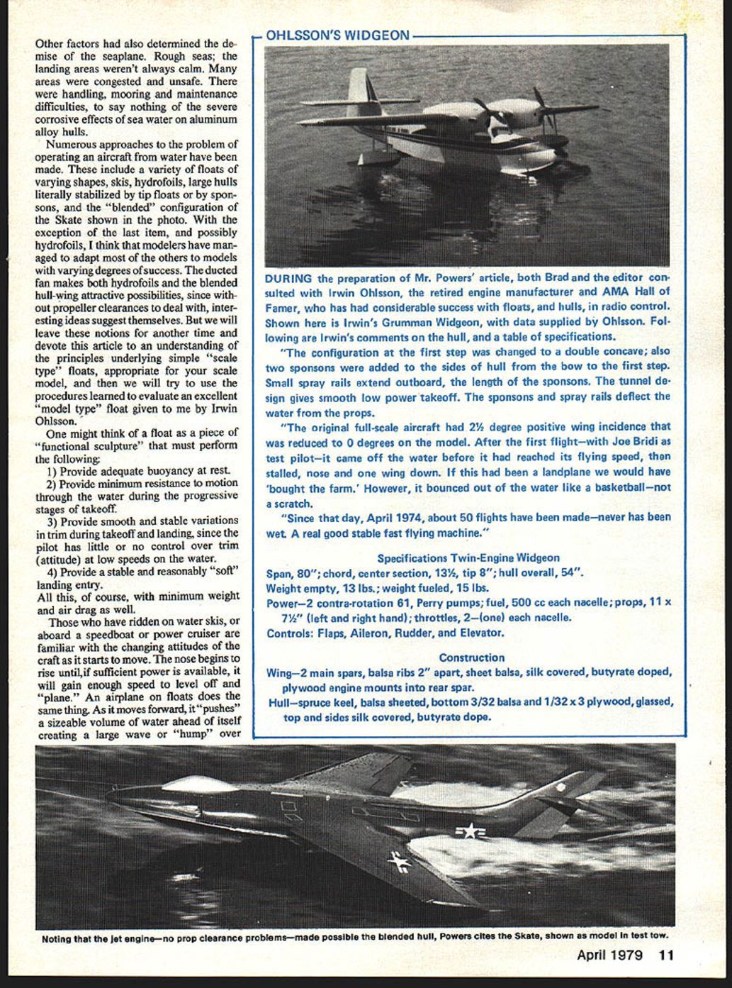
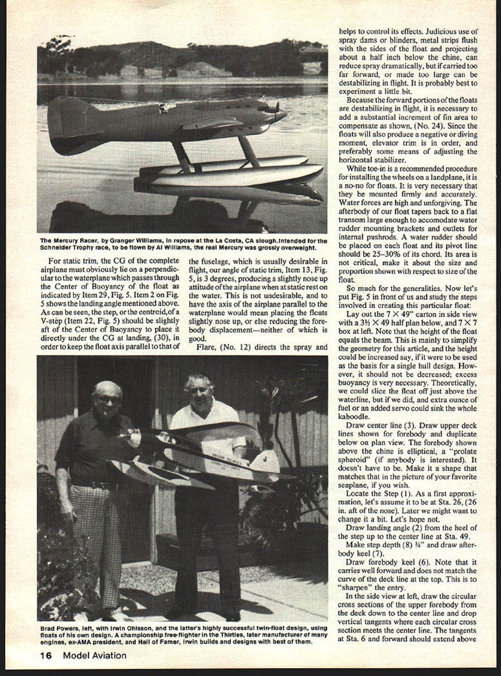
During preparation of this article, Brad Powers and the editor consulted with Irwin Ohlsson (retired engine manufacturer and AMA Hall of Famer) who has had considerable success with R/C floats and hulls. Below are Irwin's comments and a table of specifications for his Grumman Widgeon model.
Irwin's comments:
- The configuration at the first step was changed to a double concave; two sponsons were added to the sides of the hull from the bow to the first step. Small spray rails extend outboard the length of the sponsons. The tunnel design gives smooth low-power takeoff; the sponsons and spray rails deflect water from the props.
- The original full-scale aircraft had 2½° positive wing incidence; the model was reduced to 0°. On the first flight the model came off the water before it reached flying speed, then stalled, nose and one wing down. It bounced out of the water without damage. Since April 1974 about 50 flights have been made—never has been wet. Irwin calls it "a real good stable fast flying machine."
Specifications — Twin-Engine Widgeon
- Span: 80"
- Chord: center section 13½", tip 8"
- Hull overall: 54"
- Weight empty: 13 lb
- Weight fueled: 15 lb
- Power: 2 contra-rotation .61 (Perry pumps)
- Fuel: 500 cc each nacelle
- Props: 11 × 7½" (left and right hand)
- Throttles: 2 (one each nacelle)
- Controls: Flaps, Aileron, Rudder, Elevator
Construction
- Wing: 2 main spars, balsa ribs 2" apart, sheet balsa, silk covered, butyrate doped, plywood engine mounts into rear spar.
- Hull: spruce keel, balsa sheeted, bottom 3/32" balsa and 1/32" × 3" plywood, glassed; top and sides silk covered, butyrate dope.
Irwin's floats are straightforward in design, with generous step and landing angle and progressive deadrise. He provided the float dimensions, trim, and an estimated draft of 1.6 in (≈ 40% of beam) for use with the procedures discussed here.
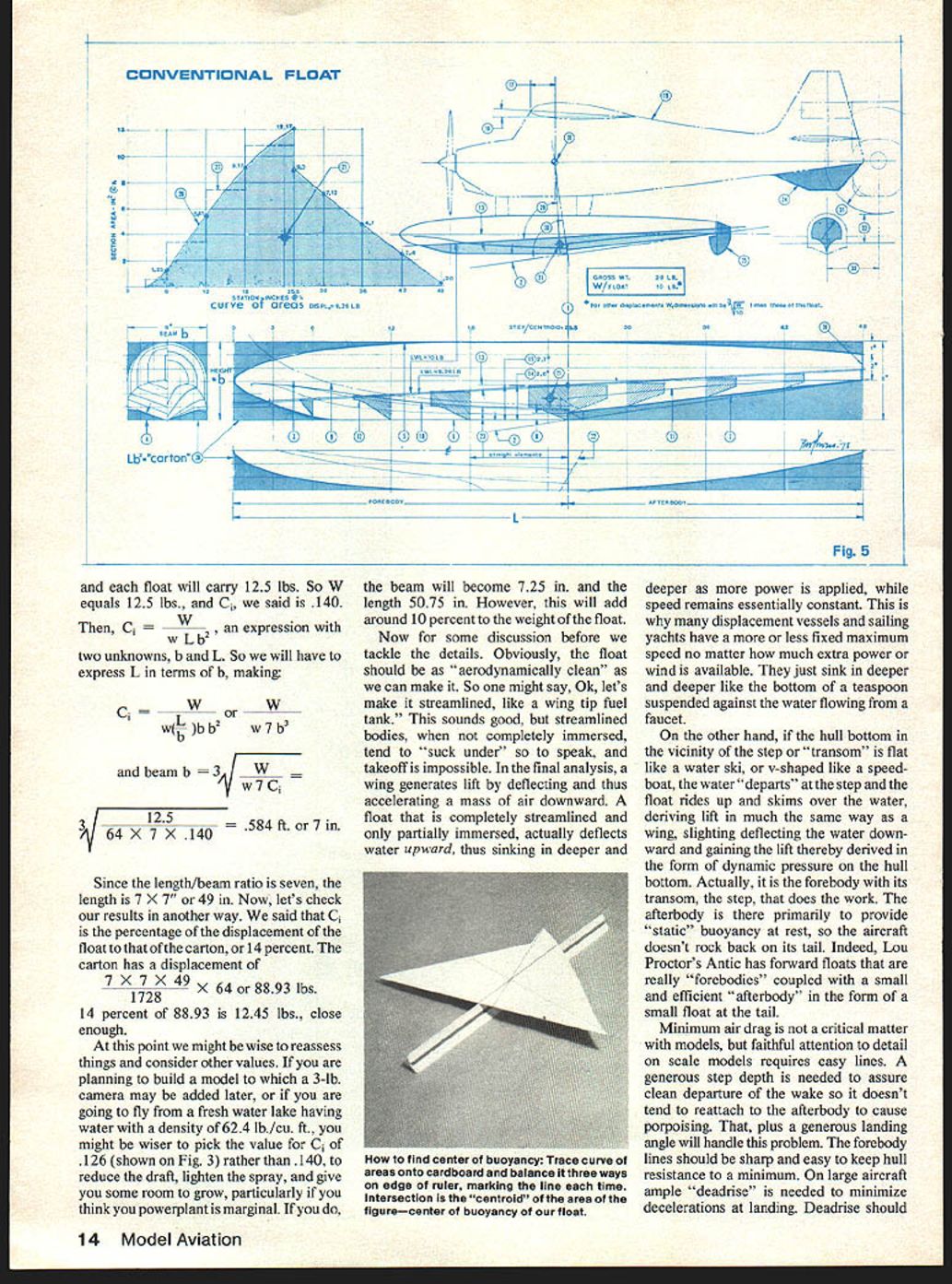
Detailed float-design procedure (summary of Fig. 5 process)
- Lay out the carton: for L/b = 7 use a 7 × 49" side-view carton, with a 3½ × 49" half-plan below, and a 7 × 7" box at left. (Height = beam for simplified geometry; extra buoyancy is desirable.)
- Draw centerline.
- Draw upper deck lines for the forebody and duplicate below on the plan view.
- Locate the step (Sta. 26 as a first approximation — 26 in aft of nose).
- Draw landing angle from the heel of the step up to the centerline at Sta. 49.
- Make step depth ~3/4" and draw afterbody keel.
- Draw forebody keel; it should carry well forward and not match the deck curve at the top to sharpen entry.
- In side view, draw circular cross sections of the upper forebody from deck down to centerline and drop vertical tangents where each cross section meets the centerline. Tangents at Sta. 6 and forward should extend above the centerline.
- Starting at the step (Sta. 26) draw the deadrise at 20°. Its intersection with the vertical tangent determines the aft point of the theoretical chine.
- Draw the theoretical chine to establish smooth variation in deadrise forward.
- At the step section draw chine flare and extend to vertical tangent to establish aft end of forebody chine.
- Draw the forebody chine; near Sta. 6 the curve reverses to lie fore-and-aft for a clean aerodynamic entry. Assume the theoretical chine lies on a curved surface touching the hull side.
- Draw deadrise and flare at each station so flare is tangent to deadrise and horizontal at the chine. Use generous radii for flare.
- Draw afterbody deadrise at each station and establish afterbody chine in end and side views.
- Using the afterbody planform, determine radii and draw the locus of these radii in side view, then complete afterbody sections in end view.
- Draw "buttock lines" and "water lines" in the end view and project into other views to ensure fairness. Adjust shapes until lines are smooth.
- Between Sta. 18 and the step, keep buttock lines straight (no fore-and-aft curvature) to insure stable planning.
- Draw a trial static load waterline sloping up and aft 3° through a point 3 in above the keel at the step.
- From end view and waterline construct the hatched immersed sections at each station.
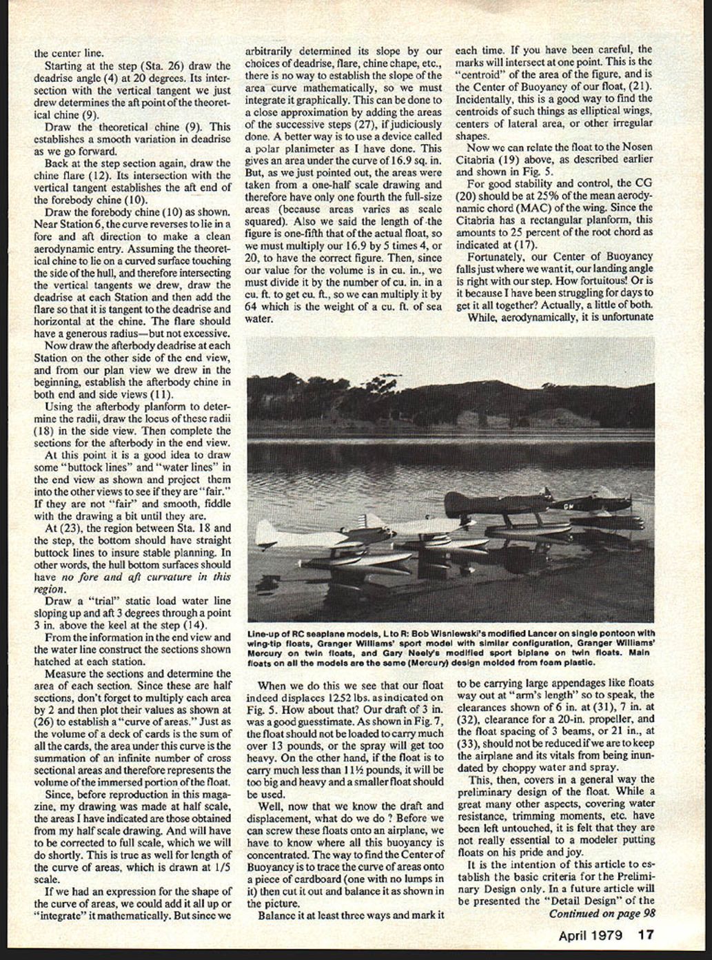
- Measure these half-sections, double each to get full-section areas, and plot them to form the "curve of areas." The integral (area under curve) equals immersed volume.
- Integrate graphically (e.g., add strips or use a polar planimeter). Correct scale factors if drawing was at reduced scale.
- Convert immersed volume to displacement (multiply cu ft by 64 lb/cu ft for sea water).
- To find the Center of Buoyancy (centroid of area under the curve), trace the curve of areas onto cardboard, cut it out, and balance it in at least three orientations. Intersection of balance marks is the centroid.
- Relate float Center of Buoyancy to aircraft CG and plan float spacing and clearances accordingly.
Notes:
- The static trim angle in the example is 3° (slight nose-up at rest).
- The step (or centroid of a V-step) should be slightly aft of the Center of Buoyancy to align under the CG at landing and keep the float axis parallel to the fuselage.
- The recommended float clearances for the Citabria example: 6 in and 7 in clearances for prop and airframe, float spacing about 3 beams (≈21 in).
- Add necessary fin area to compensate for float lateral destabilization; provide elevator trim adjustment.
- Fit water rudders on each float; pivot at 25–30% chord.
This article establishes preliminary-design criteria only. Detail design of the actual floats for the Citabria model and summary results will be presented in a future article.
Acknowledgment: Thanks to Ernest G. Stout (former Chief of Hydrodynamics at Convair) for assistance with many data presented herein.
If you build a float based on these ideas, write and let me know how it works.
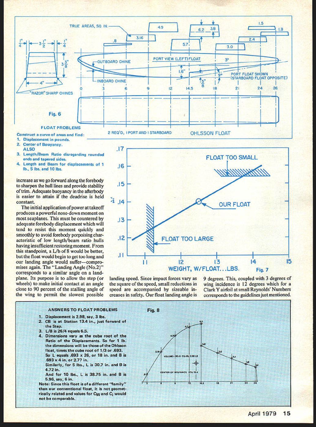
Answers to Float Problems (Fig. 8)
- Displacement is 2.98 lb (say 3 lb).
- Center of Buoyancy (CB) is at Station 13.4 in., just forward of the step.
- L/B = 26 / 4 = 6.5.
- Dimensions vary as the cube root of the ratio of the displacements. So for 1 lb the dimensions equal those of the Ohlsson float times the cube root of 1/3 ≈ 0.693:
- L = 0.693 × 26 = 18 in.
- B = 0.693 × 4 = 2.77 in.
For 5 lb:
- L = 30.7 in., B = 4.72 in.
For 10 lb:
- L = 38.75 in., B ≈ 6 in.
Note: Since this float is of a different "family" than the conventional float, it is not geometrically related and values for Cw and Ci would not be comparable.
Transcribed from original scans by AI. Minor OCR errors may remain.

