
Let's Talk About the RC Autogiro
By Jack Headley
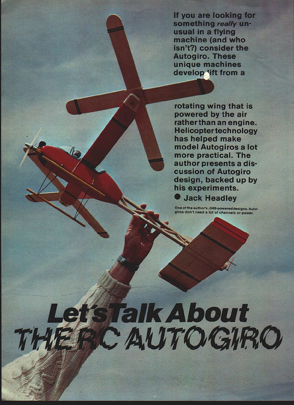
If you are looking for something really unusual in a flying machine (and who isn't?), consider the Autogiro. These unique machines develop lift from a rotating wing that is powered by the air rather than an engine. Helicopter technology has helped make model Autogiros a lot more practical. The author presents a discussion of Autogiro design, backed up by his experiments.
One of the more neglected types of radio-control models is the Autogiro, possibly because it falls somewhere between the helicopter and the more conventional fixed-wing model in performance. And yet, it's an interesting challenge, and it provides an exciting day's flying (will it fly, or won't it?). In fact, for some of my Autogiro projects, I don't dare to visit the regular flying field until I've made a few secret flights elsewhere.
The idea of this article is to look at the current state of the RC Autogiro, and (we hope) to stimulate your interest in this type of model so that we'll see a few more rotating wings at the flying field.
It will be seen, as this article progresses, that there are challenges for all types of builders here—from the modeler with a full machine shop to the type whose only interest is to cut balsa with a razor blade (myself, for example).
We'll look at three basic types of Autogiro: the simple single rotor (as invented by Cierva); the twin intermeshing type (as developed full-scale by Flettner); and the Focke-Achgelis Fa 61 type, with twin side-by-side rotors.
Single Rotor Autogiro
The single rotor Free Flight Autogiro has been around for quite some time, and can be made to fly well. The RC version, however, has not been as easy to develop, and had to go along the same learning curve as Cierva when he was developing the full-scale Autogiro.
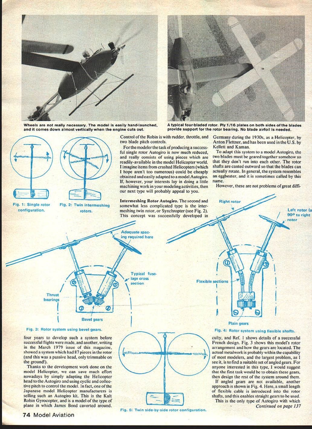
Fig. 1 shows an idealized single-rotor model, with the rotor spinning counterclockwise. When this model flies forward, the rotor lift becomes unbalanced, and the model will roll to the left. (In fact, at certain rotor revs and flight speeds, the left side of the rotor can produce no lift at all.)
For Free Flight models, which essentially fly at one speed and turn in one direction only, this rolling moment can be trimmed out by a flexible rotor hub or shaft. For the RC model, which flies at various speeds and turns in any direction, the trimming problem is not as easy. Some designers have overcome this by adding a large conventional wing, with or without aileron control. (This is really cheating, I think.) The correct approach is to mechanize the rotor blades so that the rotor forces are controlled by the flier.
The objective is easy to say, but not too easy to accomplish. The task the model Autogiro builder had was to duplicate in miniature the system that Cierva had developed, with flapping blades, drag hinges, and a tilting rotor head. That's a formidable project. One investigator reports that it took four years to develop such a system before successful flights were made, and another, writing in the March 1979 issue of this magazine, showed a system which had 87 pieces in the rotor (and this was a passive head, only trimmable on the ground!).
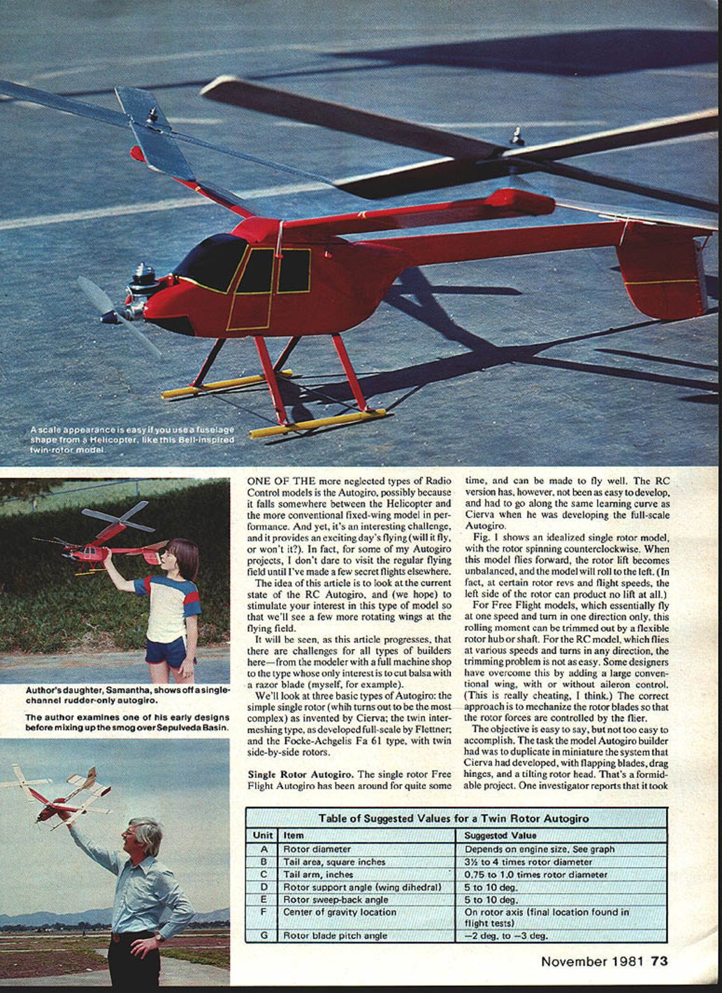
Table of suggested values for a Twin Rotor Autogiro:
- A — Rotor diameter: Depends on engine size. See graph.
- B — Tail area, square inches: 3½ to 4 times rotor diameter.
- C — Tail arm, inches: 0.75 to 1.0 times rotor diameter.
- D — Rotor support angle (wing dihedral): 5° to 10°.
- E — Rotor sweep-back angle: 5° to 10°.
- F — Center of gravity location: On rotor axis (final location found in flight tests).
- G — Rotor blade pitch angle: -2° to -3°.
Thanks to the development work done on the model helicopter, we can save much effort nowadays by simply adapting the helicopter head to the Autogiro and using cyclic and collective pitch to control the model. In fact, one of the Japanese model-helicopter manufacturers is selling such an Autogiro kit. This is the Kalt Robin Gyrocopter, a model of the type of plane in which James Bond cavorted around.
Control of the Robin is with rudder, throttle, and two-blade pitch controls.
For the modeler the task of producing a successful single-rotor Autogiro is now much reduced, and really consists of using pieces which are readily available in the model-helicopter world. I imagine items from crashed helicopters (which I hope aren't too numerous) could be cheaply obtained and easily adapted to a model Autogiro. If, however, your interests lie in doing a little machining work in your modeling activities, then our next type will probably appeal to you.
Intermeshing Rotor Autogiro
The second and somewhat less complicated type is the intermeshing twin rotor, or Synchropter (see Fig. 2). This concept was successfully developed in Germany during the 1930s as a helicopter by Anton Flettner, and has been used in the U.S. by Kellett and Kaman.
To adapt this system to a model Autogiro, the two blades must be geared together somehow so that they don't run into each other. The rotor shafts are canted outward so that the blades can actually rotate. In general, the system resembles an eggbeater, and it is sometimes called by this name.
These are not problems of great difficulty. Reference 1 shows details of a successful French design. Fig. 3 shows this model's rotor arrangement and how the gears are located. The actual metalwork is probably within the capability of most modelers, and the largest problem, as I see it, is to find a suitable set of angled gears. For anyone interested in this type, I would suggest that the first task would be to obtain these gears, then design the rest of the system around them.
If angled gears are not available, another approach is shown in Fig. 4. Here, a small length of flexible cable is introduced into the rotor shafts, and this enables straight gears to be used.
This is the only type of Autogiro with which I've had no experience. I've built the single-rotor type, both Free Flight and RC (with no success in the RC version), and many side-by-side rotor types, as you can see from the photos.
This lack of experience doesn't prevent me from making a couple of comments. The first is that this system must lead to reduced efficiency, as the lift produced must be inversely proportional to the cant angle of the rotor; the greater the cant, the less efficient the system must be. The other point concerns lateral stability. If the outward cant of the rotors represents a wing with a large anhedral, how can any turns be made in flight? Maybe a reader could shed some light on this latter point.
Twin Side-by-Side Rotor Autogiro
The last type I'll discuss is the twin side-by-side rotor system, as illustrated in Fig. 5. Several plans have been published for Autogiros of this configuration. This is the easiest type insofar as construction is concerned, and requires the same level of building skill as a simple fixed-wing conventional RC model.
Having two counter-rotating rotors means that lateral balance is achieved. Canting the rotors inward provides a dihedral effect similar to a normal wing. The rotors themselves can be built flat (which makes for easy construction), and they can be made in a simple cruciform shape, which automatically sets the blade pitch angle.
During one of my "single-channel" phases, I built several of these models—from simple sheet-profile fuselages to scale-helicopter designs, all with rudder control. You can see from the photos the sort of configuration that is possible for a single-channel model.
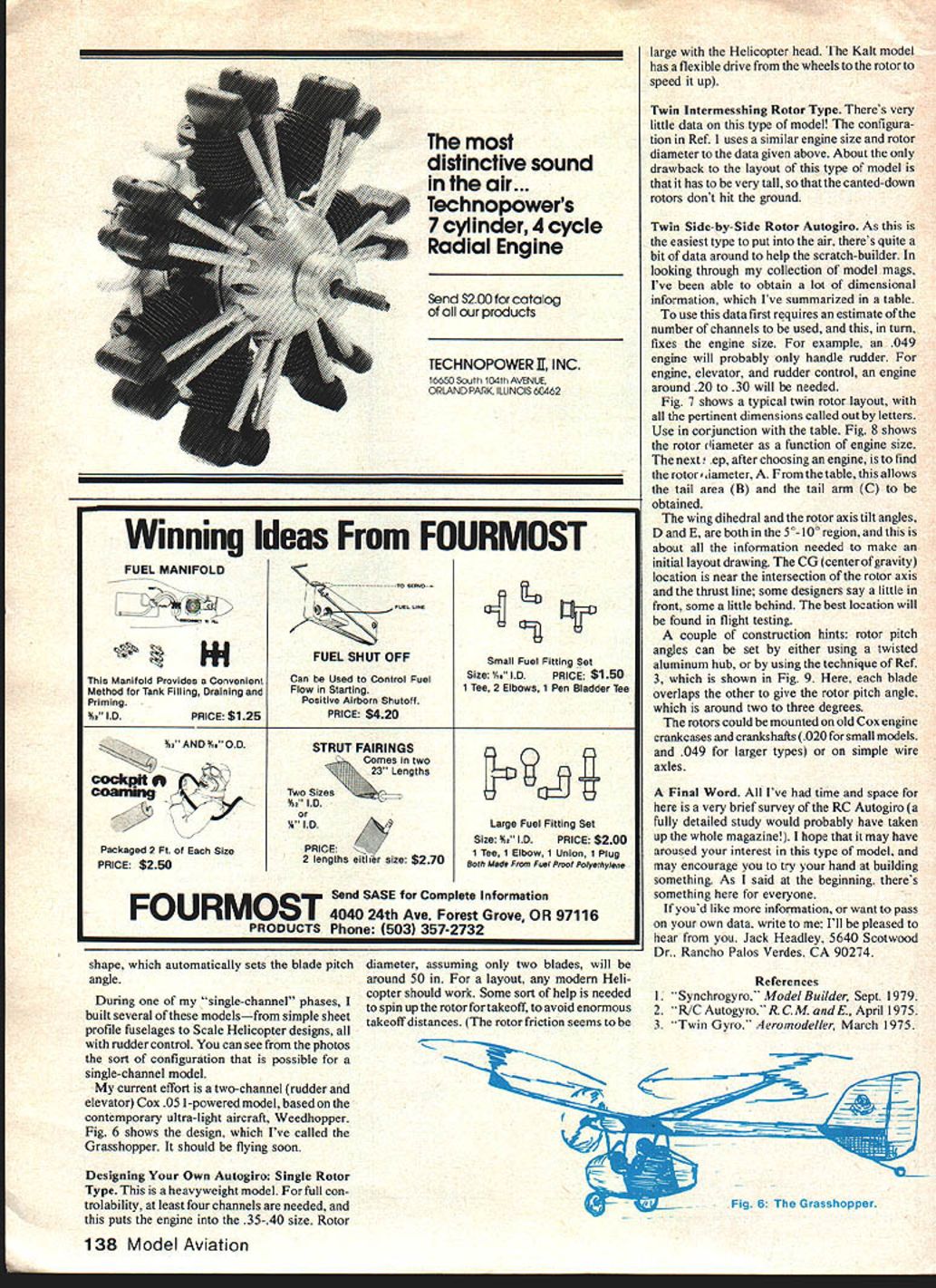
My current effort is a two-channel (rudder and elevator) Cox .051-powered model, based on the contemporary ultralight aircraft Weedhopper. Fig. 6 shows the design, which I've called the Grasshopper. It should be flying soon.
Designing Your Own Autogiro: Single Rotor Type
This is a heavyweight model. For full controllability, at least four channels are needed, and this puts the engine into the .35–.40 size. Rotor diameter, assuming only two blades, will be around 50 in. For a layout, any modern helicopter should work. Some sort of help is needed to spin up the rotor for takeoff, to avoid enormous takeoff distances. (The rotor friction seems to be large with the helicopter head. The Kalt model has a flexible drive from the wheels to the rotor to speed it up.)
Twin Intermeshing Rotor Type (Design Notes)
There's very little data on this type of model! The configuration in Reference 1 uses a similar engine size and rotor diameter to the data given above. About the only drawback to the layout of this type of model is that it has to be very tall, so that the canted-down rotors don't hit the ground.
Twin Side-by-Side Rotor Autogiro (Design Notes)
As this is the easiest type to put into the air, there's quite a bit of data around to help the scratch-builder. In looking through my collection of model mags, I've been able to obtain a lot of dimensional information, which I've summarized in the table above.
To use this data first requires an estimate of the number of channels to be used, and this, in turn, fixes the engine size. For example, an .049 engine will probably only handle rudder. For engine, elevator, and rudder control, an engine around .20 to .30 will be needed.
Fig. 7 shows a typical twin-rotor layout, with all the pertinent dimensions called out by letters. Use in conjunction with the table. Fig. 8 shows the rotor diameter as a function of engine size. The next step, after choosing an engine, is to find the rotor diameter (A). From the table, this allows the tail area (B) and the tail arm (C) to be obtained.
The wing dihedral and the rotor axis tilt angles, D and E, are both in the 5°–10° region, and this is about all the information needed to make an initial layout drawing. The CG (center of gravity) location is near the intersection of the rotor axis and the thrust line; some designers say a little in front, some a little behind. The best location will be found in flight testing.
A couple of construction hints:
- Rotor pitch angles can be set by either using a twisted aluminum hub, or by using the technique of Reference 3 (shown in Fig. 9). Here, each blade overlaps the other to give the rotor pitch angle, which is around 2° to 3°.
- The rotors could be mounted on old Cox engine crankcases and crankshafts (.020 for small models, and .049 for larger types) or on simple wire axles.
A Final Word
All I've had time and space for here is a very brief survey of the RC Autogiro (a fully detailed study would probably have taken up the whole magazine!). I hope that it may have aroused your interest in this type of model, and may encourage you to try your hand at building something. As I said at the beginning, there's something here for everyone.
If you'd like more information, or want to pass on your own data, write to me. I'll be pleased to hear from you.
Jack Headley 5640 Scotwood Dr. Rancho Palos Verdes, CA 90274
References
- "Synchrogyror," Model Builder, Sept. 1979.
- "R/C Autogyro," R.C.M. and E., April 1975.
- "Twin Gyro," Aeromodeller, March 1975.
Transcribed from original scans by AI. Minor OCR errors may remain.

