
Let's Talk About Reynolds' Numbers
By Brad Powers
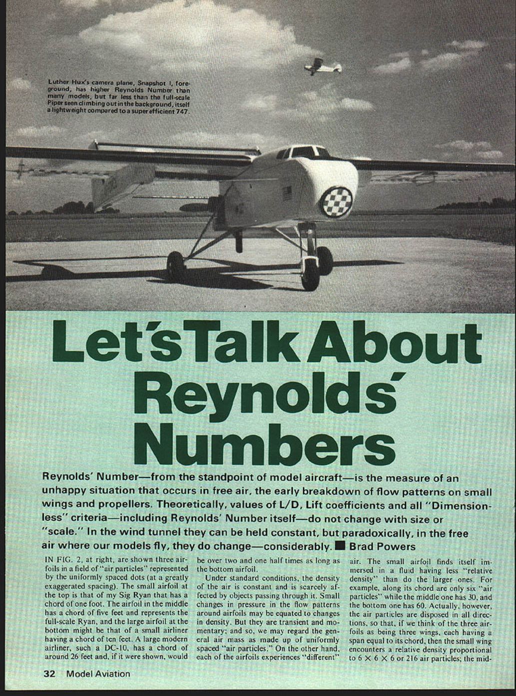
Reynolds' Number—from the standpoint of model aircraft—is the measure of an unhappy situation that occurs in free air: the early breakdown of flow patterns on small wings and propellers. Theoretically, values of L/D, lift coefficients and all "dimensionless" criteria—including Reynolds' Number itself—do not change with size or scale. In the wind tunnel they can be held constant, but paradoxically, in the free air where our models fly, they do change—considerably.
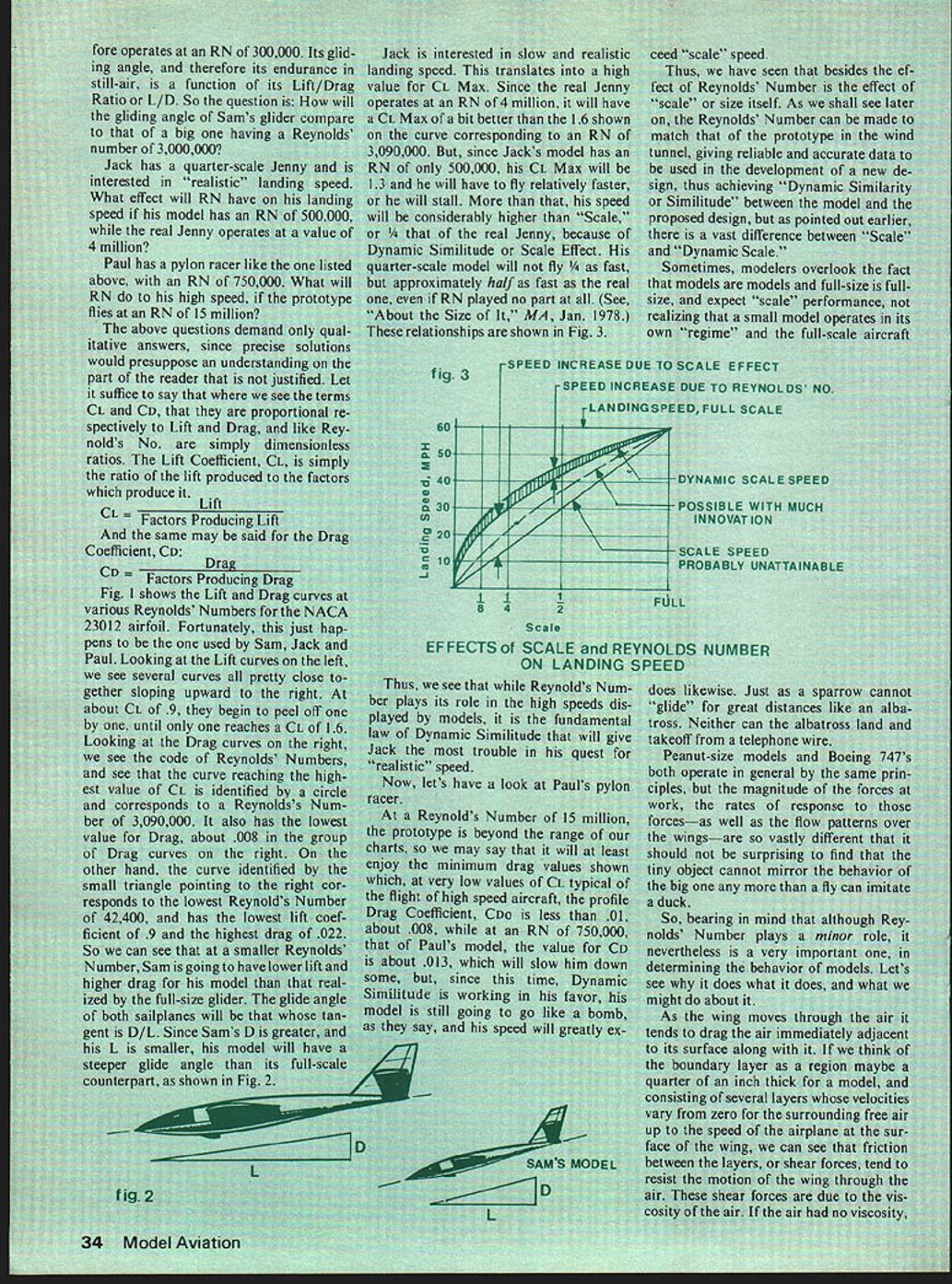
In Fig. 2 (at right) are shown three airfoils in a field of "air particles" represented by uniformly spaced dots (at a greatly exaggerated spacing). The small airfoil at the top is that of my Sig Ryan and has a chord of one foot. The airfoil in the middle has a chord of five feet and represents the full-scale Ryan, and the large airfoil at the bottom might be that of a small airliner having a chord of ten feet. A large modern airliner, such as the DC-10, has a chord of around 26 feet and, if it were shown, would be over two and one half times as long as the bottom airfoil.
Under standard conditions, the density of the air is constant and is scarcely affected by objects passing through it. Small changes in pressure in the flow patterns around airfoils may be equated to changes in density, but they are transient and momentary; so we may regard the general air mass as made up of uniformly spaced "air particles." On the other hand, each of the airfoils experiences "different" air. The small airfoil finds itself immersed in a fluid having less "relative density" than do the larger ones. For example, along its chord are only six "air particles" while the middle one has 30, and the bottom one has 60.
Actually, the air particles are disposed in all directions; so if we think of the three airfoils as three wings, each having a span equal to its chord, then the small wing encounters a relative density proportional to 6 × 6 × 6 = 216 air particles; the middle one, 30 × 30 × 30 = 27,000; and the big one at the bottom, 60 × 60 × 60 = 216,000. So the big airfoil finds itself in a fluid having 1,000 times the "relative density" of that experienced by the small airfoil.
The foregoing is true only when the airfoils are at rest or when they are moving at the same speed. If the small airfoil is moved through the air at very high speed compared with that of the large airfoils, it is possible for it to encounter just as many air particles in a unit of time and thus experience comparable "density."
Now, the density (or mass) of the air times its velocity is a measure of the momentum, or strength, of the flow over the wing. As we shall see, flows with high momentum tend to remain established to higher angles of attack without being disrupted than do flows having small momentum. The disruptive factors which tend to impede the flow are adverse pressures and the cohesive forces or viscosity of the air itself.
All fluids and gases have viscosity. Everyone is familiar with the viscosity or "stickiness" of heavy motor oil, honey, molasses, etc. Compared with these, the viscosity of water is quite low, and that of air is very small indeed, but it is nevertheless a factor to be reckoned with. So let's see if we can put these factors into some kind of mathematical relationship.
The flow has to do with density, speed, and size. The resistance has to do with viscosity. So let D represent density, V represent speed or velocity, L represent size or length, and v represent viscosity.
If we increase (or decrease) density, velocity or length, we affect the flow in proportion, so we can say that the flow is the product of these items, or D × V × L. If we relate the flow to the factor which tends to impede the flow, we can write D V L / v and say that it is a useful yardstick for comparing one flow pattern to another. And indeed it is, because if we substitute ρ (rho) for D and μ (mu) for v, we have ρ V L / μ, which is the expression for Reynolds' Number.
So Reynolds' Number may be said to be the ratio of the momentum of the flow to the cohesive or viscous properties which impede the flow. Thus, high values of Reynolds' Number are good, while the small values characteristic of models are not so good. At small values of RN the flow pattern in the boundary layer is very sensitive to the build-up of adverse pressures downstream, so that small wings and propellers are unable to sustain smooth flow to the angles of attack attained by large wings and propellers. This results in smaller values for lift and higher values for drag proportionately. Thus L/D is decreased, which is disheartening to sailplane (endurance and range) buffs. Landing speeds are increased, which is sad news for scale buffs. And high speeds are reduced, which can be depressing to pylon buffs.
First, let's go back to our expression for RN and define each term:
- ρ = Mass density of standard air in slugs per cubic foot.
- μ = Viscosity of standard air in pound-seconds per square foot.
- V = Velocity in mph.
- L = A characteristic dimension, usually the wing chord, in feet.
Under standard conditions, ρ equals 0.002377. For general usage this is usually rounded off to 0.0024. So we can say:
Reynolds' Number ≈ 10,000 × mph × chord (in feet).
Thus, a Peanut scale model having a chord of, say, 2 inches and flying at a speed of 15 mph operates at a Reynolds' Number of 10,000 × 15 × (2/12) ≈ 25,000, while our DC-10 flying at 500 mph and having a mean aerodynamic chord (MAC) of about 26 feet would be operating at a Reynolds' Number in the neighborhood of 130 million.
To better get the "feel" of the values of RN appropriate to models, let's take some more examples:
- 3" chord, 20 mph → Reynolds' Number ≈ 50,000 (Small trainer)
- 6" chord, 30 mph → Reynolds' Number ≈ 150,000 (Small trainer)
- 12" chord, 50 mph → Reynolds' Number ≈ 500,000 (Proctor Antic)
- 2' chord, 75 mph → Reynolds' Number ≈ 937,500 (1/4-scale Nosen)
- 6' chord, 150 mph → Reynolds' Number ≈ 750,000 (Pylon racer)
- 5' chord, 150 mph → Reynolds' Number ≈ 7,500,000 (Full-scale Ryan ST)
So we see that quarter-scale monsters at moderate speeds, and smaller models even at pretty high speeds, have small values for RN compared with a full-scale Ryan, which is itself a "small" airplane by today's standards. Now let's look at some typical situations to see what effects differing values of RN can have.
Sam has a sailplane that flies at around 40 mph and has a chord of 9 in. It therefore operates at a Reynolds' Number of around 300,000. Its gliding angle, and therefore its endurance in still air, is a function of its lift/drag ratio or L/D. How will the gliding angle of Sam's glider compare to that of a big one having a Reynolds' Number of 3,000,000?
Jack has a quarter-scale Jenny and is interested in "realistic" landing speed. What effect will RN have on his landing speed if his model has an RN of 500,000 while the real Jenny operates at a value of 4,000,000?
Paul has a pylon racer like the one listed above, with an RN of 750,000. What will RN do to his high speed if the prototype flies at an RN of 15,000,000?
The above questions demand only qualitative answers, since precise solutions would presuppose an understanding on the part of the reader that is not justified here. Let it suffice to say that where we see the terms CL and CD, they are proportional respectively to lift and drag, and like Reynolds' Number are simply dimensionless ratios.
- CL = Lift / Factors producing lift
- CD = Drag / Factors producing drag
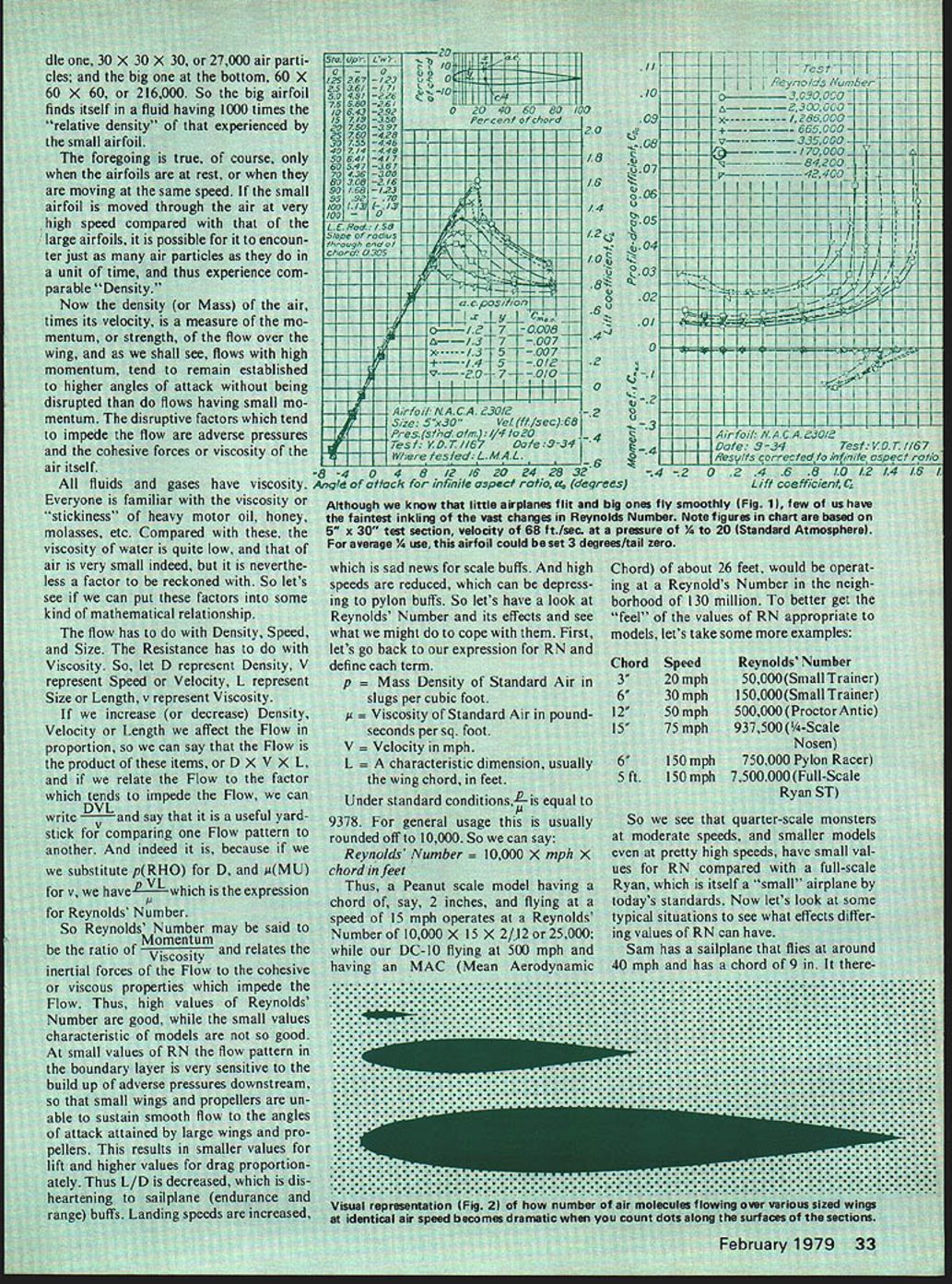
Fig. 1 shows the lift and drag curves at various Reynolds' Numbers for the NACA 23012 airfoil. Fortunately, this just happens to be the one used by Sam, Jack and Paul. Looking at the lift curves on the left, we see several curves all pretty close together sloping upward to the right. At about CL ≈ 0.9 they begin to peel off one by one, until only one reaches a CL of 1.6. Looking at the drag curves on the right, the curve reaching the highest value of CL is identified by a circle and corresponds to a Reynolds' Number of 3,090,000. It also has the lowest value for drag, about 0.008, in the group of drag curves. On the other hand, the curve identified by the small triangle corresponds to the lowest Reynolds' Number of 42,400 and has the lowest lift coefficient (≈ 0.9) and the highest drag (≈ 0.022).
So we can see that at a smaller Reynolds' Number, Sam is going to have lower lift and higher drag for his model than that realized by the full-size glider. The glide angle of both sailplanes will be the angle whose tangent is D/L. Since Sam's D is greater and his L is smaller, his model will have a steeper glide angle than its full-scale counterpart, as shown in Fig. 2.
Jack is interested in slow and realistic landing speed. This translates into a high value for CL,max. Since the real Jenny operates at an RN of 4,000,000, it will have a CL,max a bit better than the 1.6 shown on the curve corresponding to an RN of 3,090,000. But since Jack's model has an RN of only 500,000, his CL,max will be about 1.3 and he will have to fly relatively faster. He will be considered higher than "scale" because of dynamic similitude or scale effect. His quarter-scale model will not fly one quarter as fast, but approximately half as fast as the real one, even if RN played no part at all. (See "About the Size of It," MA, Jan. 1978.) These relationships are shown in Fig. 3.
Thus, while Reynolds' Number plays its role in the high speeds displayed by models, it is the fundamental law of dynamic similitude that will give Jack the most trouble in his quest for "realistic" speed.
Now, Paul's pylon racer: at a Reynolds' Number of 15,000,000, the prototype is beyond the range of our charts. We may say that it will at least enjoy the minimum drag values shown which, at very low values of CL typical of high-speed flight, give CD0 less than 0.01, or about 0.008. At an RN of 750,000 (Paul's model), the value for CD is about 0.013, which will slow him somewhat, but since dynamic similitude is working in his favor, his model is still going to be very fast and will greatly exceed "scale" speed.
Thus, we have seen that besides the effect of Reynolds' Number there is the effect of "scale" or size itself. As we shall see later on, the Reynolds' Number can be made to match that of the prototype in the wind tunnel, giving reliable and accurate data to be used in the development of a new design, thus achieving dynamic similarity between the model and the proposed design. But, as pointed out earlier, there is a vast difference between "scale" and "dynamic scale."
Sometimes modelers overlook the fact that models are models and full-size is full-size, and expect "scale" performance, not realizing that a small model operates in its own regime and the full-scale aircraft does likewise. Just as a sparrow cannot glide for great distances like an albatross, neither can the albatross land and take off from a telephone wire.
Peanut-size models and Boeing 747s both operate by the same principles, but the magnitude of the forces at work, the rates of response to those forces—as well as the flow patterns over the wings—are so vastly different that it should not be surprising to find that the tiny object cannot mirror the behavior of the big one any more than a fly can imitate a duck.
So, bearing in mind that although Reynolds' Number plays a minor role, it nevertheless is a very important one in determining the behavior of models, let's see why it does what it does and what we might do about it.
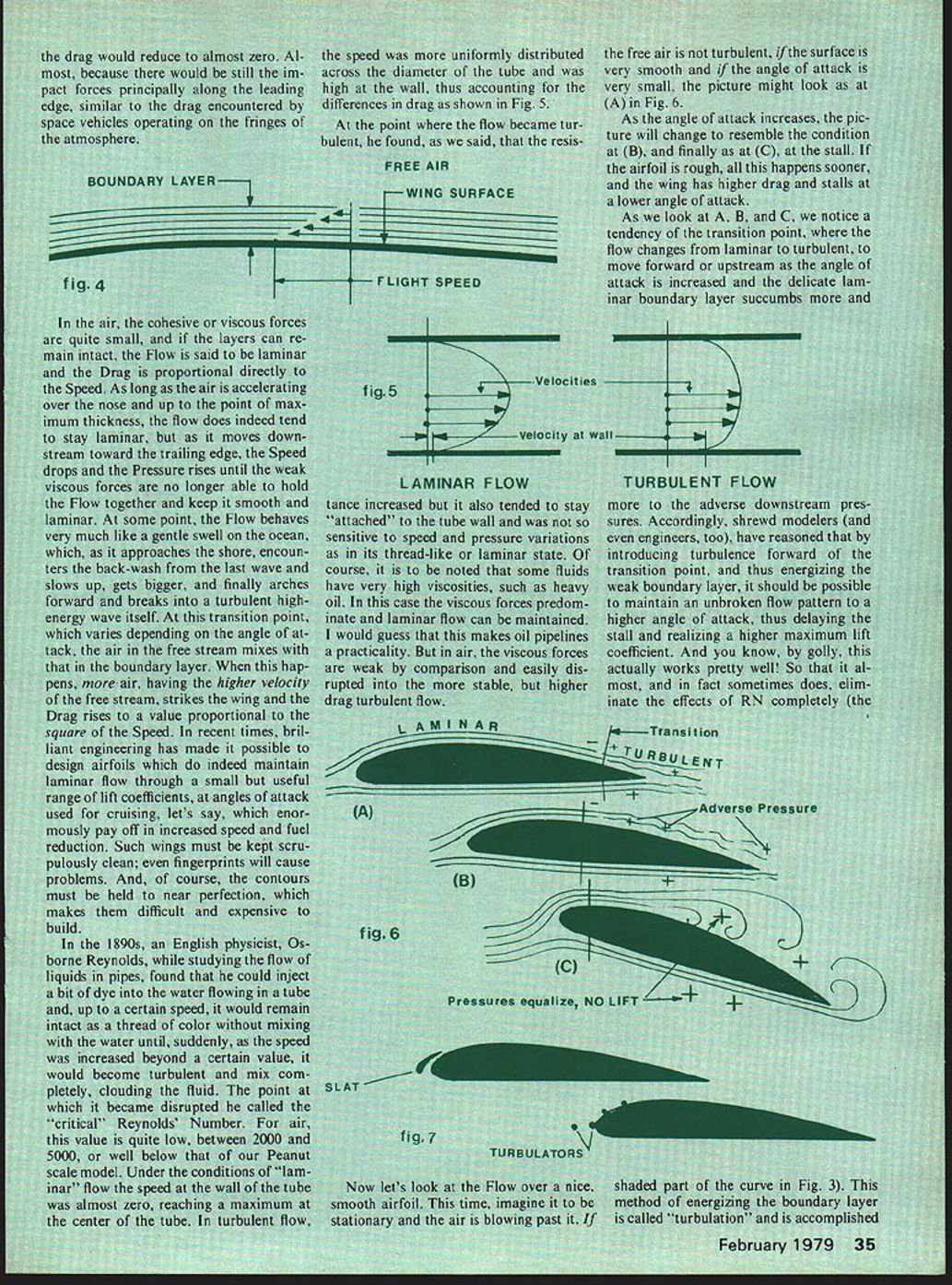
As the wing moves through the air it tends to drag the air immediately adjacent to its surface along with it. If we think of the boundary layer as a region maybe a quarter of an inch thick for a model, consisting of several layers whose velocities vary from zero at the surface up to the speed of the airplane in the free stream, we can see that most of the loss between the layers—or shear forces—tend to resist the motion of the wing through the air. These shear forces are due to the viscosity of the air. If the air had no viscosity, the drag would reduce to almost zero—almost, because there would still be impact forces principally along the leading edge, similar to the drag encountered by space vehicles operating on the fringes of the atmosphere.
In the air, the cohesive or viscous forces are quite small, and if the layers can remain intact, the flow is said to be laminar and the drag is proportional directly to the speed. As long as the air is accelerating over the nose and up to the point of maximum thickness, the flow does indeed tend to stay laminar, but as it moves downstream toward the trailing edge the speed drops and the pressure rises until the weak viscous forces are no longer able to hold the flow together and keep it smooth and laminar.
At some point the flow behaves very much like a swell on the ocean which, as it approaches the shore, encounters the back-wash from the last wave, slows up, grows and finally arches forward and breaks into a turbulent high-energy wave. At this transition point, which varies depending on the angle of attack, the air in the free stream mixes with that in the boundary layer. When this happens, more air having the higher velocity of the free stream strikes the wing and the drag rises to a value proportional to the square of the speed.
In recent times, brilliant engineering has made it possible to design airfoils which do indeed maintain laminar flow through a small but useful range of lift coefficients at cruising angles of attack, which enormously pays off in increased speed and fuel reduction. Such wings must be kept scrupulously clean; even fingerprints will cause problems. And, of course, the contours must be held to near perfection, which makes them difficult and expensive to build.
In the 1890s an English physicist, Osborne Reynolds, while studying the flow of liquids in pipes, found that he could inject a bit of dye into the water flowing in a tube and, up to a certain speed, it would remain intact as a thread of color without mixing with the water until, suddenly, as the speed was increased beyond a certain value, it would become turbulent and mix completely, clouding the fluid. The point at which it became disrupted he called the critical Reynolds' Number. For air this value is quite low—between about 2,000 and 5,000—well below that of our Peanut scale model.
Under laminar-flow conditions the speed at the wall of the tube was almost zero, reaching a maximum at the center of the tube. In turbulent flow the speed was more uniformly distributed across the diameter of the tube and was higher at the wall, thus accounting for the differences in drag.
At the point where the flow became turbulent, Reynolds found that the resistance increased but the flow also tended to stay "attached" to the tube wall and was less sensitive to speed and pressure variations than in its thread-like or laminar state. Of course, some fluids have very high viscosities (such as heavy oil) and in this case the viscous forces predominate and laminar flow can be maintained.
If the free air is not turbulent, if the surface is very smooth and if the angle of attack is very small, the flow over an airfoil may remain laminar as in condition (A) of Fig. 6. As the angle of attack increases, the picture will change to resemble condition (B), and finally to (C) at the stall. If the airfoil is rough, all this happens sooner: the wing has higher drag and stalls at a lower angle of attack.
As we look at A, B and C, we notice a tendency of the transition point—where the flow changes from laminar to turbulent—to move forward (upstream) as the angle of attack increases and the delicate laminar boundary layer succumbs more and more to adverse downstream pressures. Accordingly, shrewd modelers (and engineers, too) have reasoned that by introducing turbulence forward of the transition point, and thus energizing the weak boundary layer, it should be possible to maintain an unbroken flow pattern to a higher angle of attack, thus delaying the stall and realizing a higher maximum lift coefficient. And it actually works pretty well!
This method of energizing the boundary layer is called "turbulation" and is accomplished by several means: from the use of slats to stretching wires (as shown in Fig. 7), or even by the application of fine sandpaper along the nose of the airfoil. While this rules out any hope of low drag due to laminar flow, it increases the chances of realizing slower, more realistic speeds that are the result of higher lift. I know of no precise rules for locating turbulators; it is probably best to experiment a little.
From all this we begin to see that the problem is really one of "keeping the boundary layer moving." There are other ways to do this, and we will look at some of them. The only problem is they may or may not be accepted by purists whose business it is to judge such things. For example, full-span flaps plus turbulators might produce fairly realistic landing speeds, but the judges would say they are not on the prototype and are therefore illegal. Even a ten percent increase in the dimensions of the wing will increase its area over twenty percent and thus permit slower speeds without changing its standoff scale appearance very much—if the judges will allow such hanky-panky.
Countermeasures: What can we do to fight back at the adverse effects of Reynolds' Number?
Porpoises can dive under and swim circles around a power cruiser that is underway at good speed. It is my understanding that they have a built-in "ripple effect" in their surface musculature that sort of "pushes" the boundary layer downstream, thus maintaining laminar flow and its low-drag benefits—i.e., they "keep the boundary layer moving." Besides turbulation, just mentioned, there are other possibilities:
- Pressure: Boundary-layer control by pressure is a way to energize the boundary layer and keep it moving.
- Suction: The boundary layer can be kept moving by relieving the adverse downstream pressures by suction.
For most models such suggestions as boundary-layer control using pressure or suction would be overkill. However, the advent of the "biggies" may bring about a whole new ball game. A quarter-scale model powered by something like a Quadra engine can carry around five pounds or so of payload which might be in the form of a small air pump (such as used to inflate tires and rubber mattresses) and which could derive its power from the rear shaft extension in the case of the Quadra. I haven't given this the thought it deserves and am not aware whether the benefits to be derived are enough to offset the weight of such a device, but it is an idea worth looking into in the interest of achieving more realistic landing speeds for large scale models.
Cheating: As mentioned earlier, "cheating"—increasing wing area slightly, preferably in a spanwise direction to increase aspect ratio—should bring faster benefits with small changes than would small changes in chord to effect small changes in Reynolds' Number.
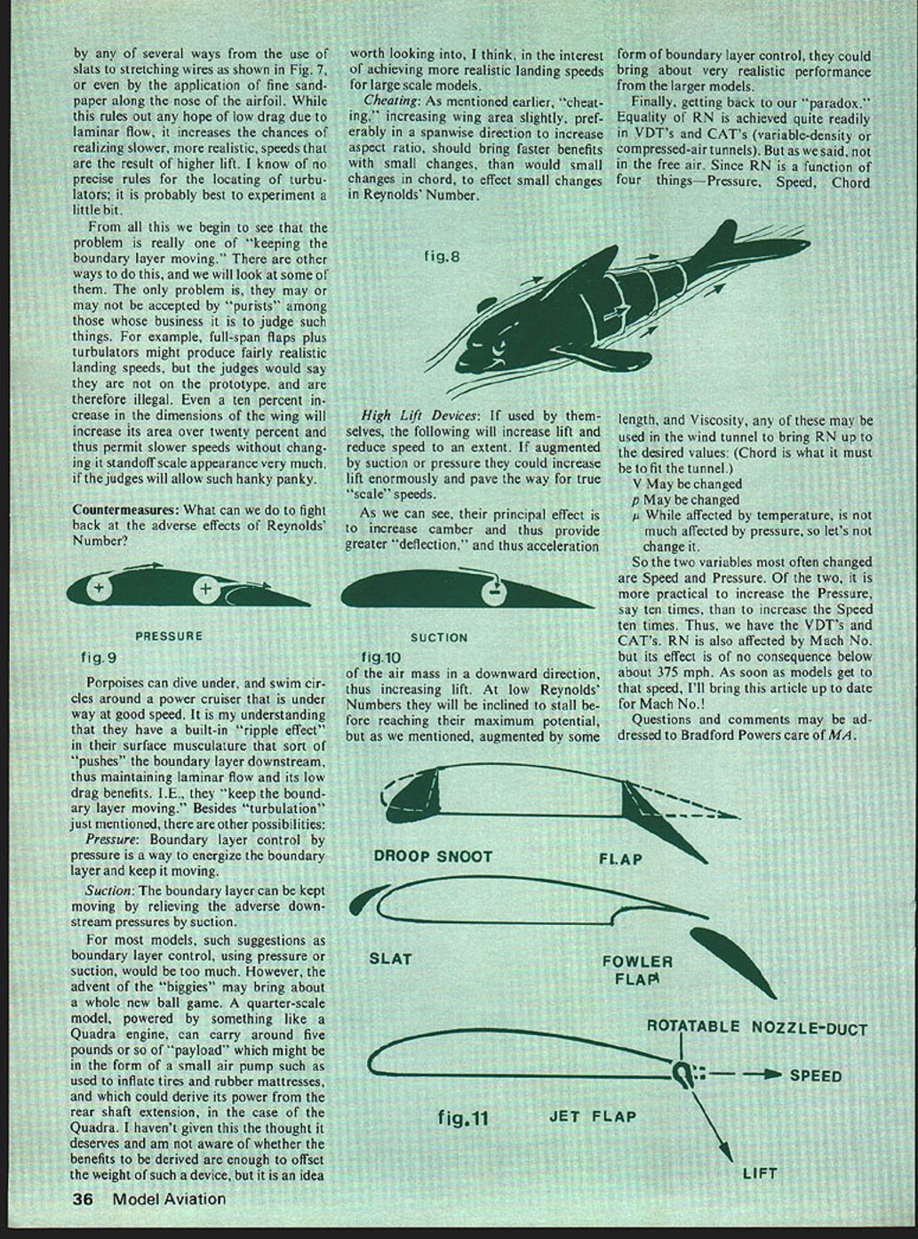
High-lift devices: If used by themselves, the following will increase lift and reduce speed to an extent. If augmented by suction or pressure they could increase lift enormously and pave the way for true "scale" speeds. Their principal effect is to increase camber and thus provide greater deflection and thus acceleration of the air mass in a downward direction, increasing lift. At low Reynolds' Numbers they will be inclined to stall before reaching their maximum potential, but augmented by some form of boundary-layer control they could bring about very realistic performance from the larger models.
Finally, getting back to our "paradox": equality of RN is achieved quite readily in VDTs and CATs (variable-density or compressed-air tunnels), but as we said, not in the free air. Since RN is a function of four things—pressure, speed, chord length and viscosity—any of these may be used in the wind tunnel to bring RN up to the desired values (chord is what it must be to fit the tunnel).
- V may be changed.
- ρ may be changed.
- μ, while affected by temperature, is not much affected by pressure, so let's not change it.
So the two variables most often changed are speed and pressure. Of the two, it is more practical to increase the pressure, say ten times, than to increase the speed ten times. Thus, we have the VDTs and CATs. RN is also affected by Mach number but its effect is of no consequence below about 375 mph. As soon as models get to that speed, I'll bring this article up to date for Mach number!
Questions and comments may be addressed to Bradford Powers care of M.A.
Transcribed from original scans by AI. Minor OCR errors may remain.

