
Letters To The Editor
All letters will be carefully considered; those of general interest will be used. Send to Model Aviation, 1810 Samuel Morse Dr., Reston, VA 22090.
RC History
I have enjoyed reading the recent three-part article on the history of RC flying. I have been a ham for 25 years; however, I have only been involved with RC flying for about two years. I was surprised to see some fairly well-known names in ham radio over the years also involved in RC model aircraft.
I hope that I am able to enjoy this hobby as much as I have enjoyed ham radio.
Keep up the good work.
Glenn R. Kurzenknabe, K3SWZ New Cumberland, PA
Airplane Conversions
I have found several airplanes that have been converted into restaurants, night clubs, and motels around the country. I would like to put together a pamphlet on what and where to find these kinds of airplanes. I'd also have a list of all museums of warplanes and a separate list of warplanes permanently stationed outside. Last, there will be pictures and a brief story of currently existing wartime landmarks. For instance, there is a restored watch tower that was used to spot enemy subs on the East Coast.
If anyone has a picture and/or address of converted airplanes, museums (especially small, unknown ones), warplanes in a field, and wartime landmarks, please let me know.
Michael A. Blaugher 124 E. Foster Parkway Ft. Wayne, IN 46806
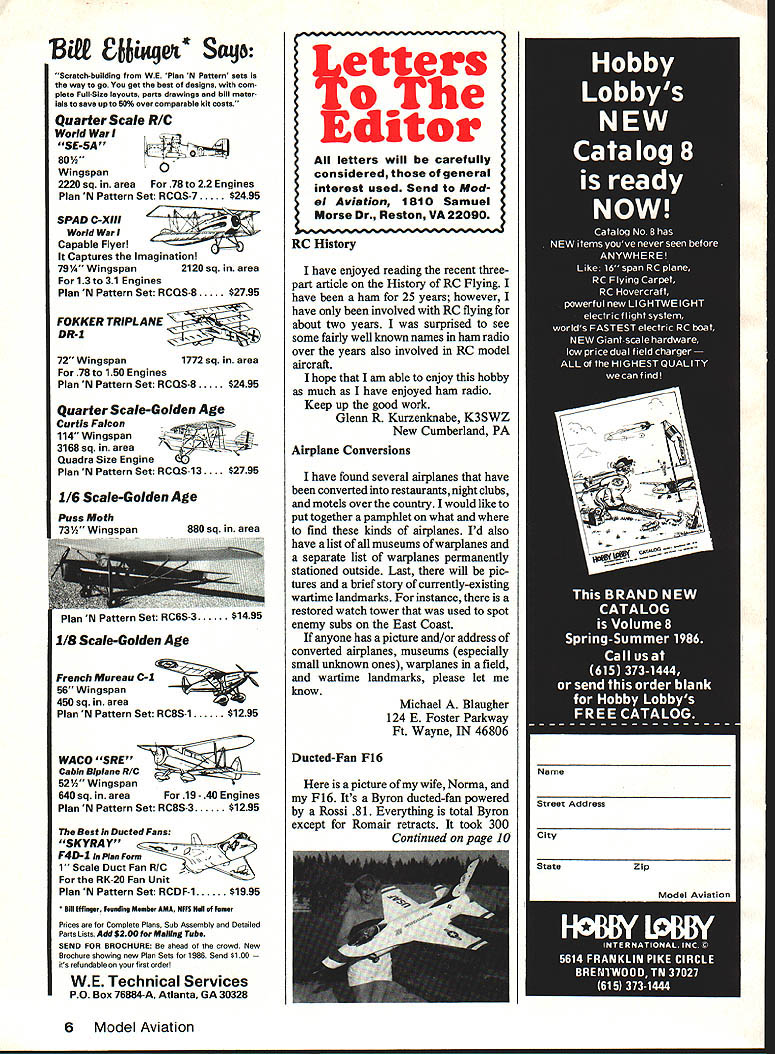
Ducted-Fan F16
Here is a picture of my wife, Norma, and my F16. It's a Byron ducted-fan powered by a Rossi .81. Everything is total Byron except for Romair retracts. It took 300 hours to complete, and it hasn't been flown yet. I've started entering it in model air show static displays, and it took first prize at Coeur d'Alene.
Norma also flies models. She has an Eagle and loves it.
We both belong to the Four Mound Model RC Club in Spokane, WA. Our field is 700 x 350 ft, which should be good for the F16. Wish me luck.
We love your magazine, so keep up the good work.
Jim Posey Nine Mile Falls, WA
Both Correct!
Recent letters concerning airfoils (John Brownlee in the February 1986 issue and Brad Powers in the May 1986 issue) recall a memorable line in a popular film of a few years ago: "What we have here is a failure to communicate." It's a heated argument, but their only difference is one of visualization—how each chooses to understand a rather complex physical phenomenon. Both are right.
I suppose that this is caused by something like a generation gap. From reading his articles, I understand that Brad Powers is, like myself, a retired engineer and probably learned his aerodynamics in the Thirties. Mr. Brownlee, apparently, has also been educated in the same field but perhaps 20 years or so later.
Early NACA (NASA's predecessor) airfoil data always presented "center of pressure" (C.P.) rather than "aerodynamic center" (A.C.) location. C.P. is defined as pitching moment divided by lift. On cambered airfoils, this quantity varies with angle of attack. But thin-airfoil theory predicts, and wind tunnel data verifies, that all cambered sections have a constant pitching moment together with a fixed A.C. (center of lift) over their useful angle of attack range. This apparent paradox—a fixed A.C. and a moving C.P.—has confused both modelers and full-scale aero engineers for 60 years or more. Possibly for this reason, the NACA changed its early format sometime in the Thirties. All airfoil data is now shown in a lift-drag-pitching moment about the A.C. format (note that there is no moment about the C.P.). A.C. is defined as the point about which the pitching moment is constant. With this convention, lift is assumed to act at the A.C., which is what a fixed position on each section (usually between 23% and 26% chord—thickness has some effect on its location).
How do you resolve this "paradox"? There is no paradox. When you divide a fixed moment by a force that varies with angle of attack, obviously you get a C.P. that varies with the same parameter. Simply remember, you cannot speak of A.C. and C.P. simultaneously; they are two different ways of describing the same thing. If you assume lift acts at the C.P., there is no airfoil-produced pitching moment; if you place it at the A.C., there is a constant (almost) pitching moment due to airfoil camber. But it's immaterial which convention is chosen; both concepts are correct.
Their "Clark Y" wing discussion was similar. Both are right in their own context. Powers is right: a short-nosed fuselage, attached to a wing at a positive incidence angle, will add a nose-up moment. But Brownlee was also right: typically, this will not be enough to trim a useful lift coefficient. But give me a long, noseless fuselage shaped like an inverted airfoil, then... On the other hand, while it is correct, Powers' statement that "Clark Y" airfoils with upturned elevons are suitable for tailless designs is a weak argument. That's not a "Clark Y" anymore.
Joe Tschirgi Nanjing, China
With this letter, we'd like to bring this discussion to a close.
Bits and Pieces
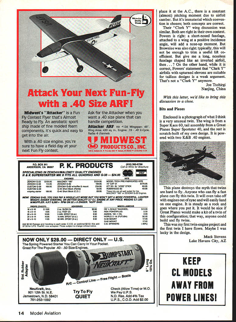
Enclosed is a photograph of what I think is a very unusual twin. The wing is from a Super Kaos 60, the tail assembly from a Great Planes Super Sportster 40, and the rest is scratch-built of my own design. It is powered with two K&B .40 engines.
This plane destroys the myth that twins are hard to fly. Anyone who can fly a fast plane can fly this twin. It will even take off with engines out of sync and will easily land on one engine. It is steady as a rock and goes where you put it. It would be nice if Great Planes would make it a kit of a twin of this configuration; that way, anyone could build and fly twins.
This was my first twin-engine project and the first twin I have flown. Maybe I was lucky in the design.
Mack Stevens Lake Havasu City, AZ
Transcribed from original scans by AI. Minor OCR errors may remain.

