
Letters To The Editor
All letters will be carefully considered; those of general interest will be used. Send to Model Aviation, 1810 Samuel Morse Dr., Reston, VA 22090.
One for Our Side
The Seminole RC Club of Tallahassee, FL, won a big one yesterday (June 9). This was thanks to AMA's help and a two‑year game plan.
First, we got involved in civic affairs. If we got a chance to fly, we flew — parades, mall shows, etc. Once a month we had groups as guests at our field — from Boy Scouts to the Baptist Children's Home. We lobbied our city, county, and state officials and got the facts about landfill closure. We did our homework.
When you get down to brass tacks, it was the club membership as a whole who, in the last week before we went before the commission, got off their duffs to call their commissioners and show up in force at the meeting. Even though the county staff had recommended that we not be on the landfill, we got seven out of seven votes.
It will be a little under two years before we can break ground to allow time for settlement. This will give us time for planning and developing a good design. This will be our home flying field for the next 20 years. There is asphalt in our future!
Thanks again.
(P.S. Flying sites are getting to be like drive‑in movies — hard to find. If you have one, take care of it. We can't have this old saying in our sport: "Here today, gone tomorrow.")
Sonny Branch V.P., Seminole RC Club Tallahassee, FL
Even Sweeter
I have enclosed a picture of my most recent modeling endeavor. This was to be a Midwest Giant Sweet'n Low Stik, but I decided to cosmetically alter it a little bit. I left the wings and horizontal stabilizer in the stock shape but changed the vertical stabilizer and rudder to a more pleasing shape.
The fuselage was built as the kit described. Then, with formers and sheeting, I tapered it from the firewall rearward to allow for an instrument panel and cockpit. The turtleback is of former‑and‑stringer construction. I also included navigational lights and wingtip strobes with form‑fitting butyrate lenses. The cowling was formed using a plug shaped from Styrofoam with Safe‑T‑Poxy and layers of 3‑oz. fiberglass cloth. The spinner, cowling, landing gear, and wheel pants were painted with MonoKote‑matching yellow Perfect Paint. The rest of the airplane was covered with MonoKote in yellow, red, orange, and metallic plum with white lettering.
I think you'll see it's not the average Stik.
Neal L. Martin Davenport, IA
Fierce Arrow Revisited
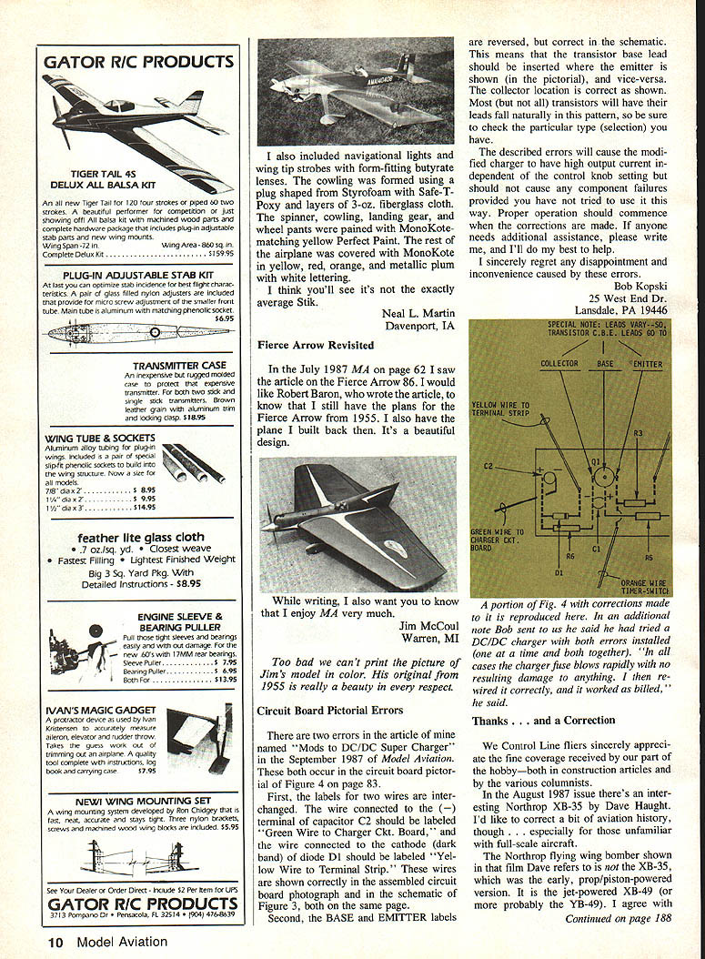
In the July 1987 MA on page 62 I saw the article on the Fierce Arrow 86. I would like Robert Baron, who wrote the article, to know that I still have the plans for the Fierce Arrow from 1955. I also have the plane I built back then. It's a beautiful design.
While writing, I also want you to know that I enjoy MA very much.
Jim McCoul Warren, MI
Circuit Board Pictorial Errors
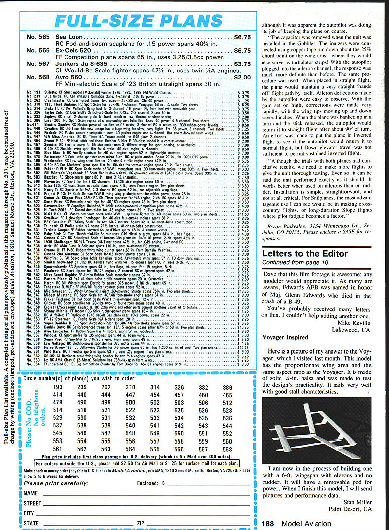
There are two errors in my article "Mods to DC/DC Super Charger" in the September 1987 issue of Model Aviation. Both occur in the circuit board pictorial of Figure 4 on page 83.
First, the labels for two wires are interchanged. The wire connected to the (−) terminal of capacitor C2 should be labeled "Green Wire to Charger Ckt. Board," and the wire connected to the cathode (band) of diode D1 should be labeled "Yellow Wire to Terminal Strip." These wires are shown correctly in the assembled circuit board photograph and in the schematic of Figure 3, both on the same page.
Second, the BASE and EMITTER labels are reversed, but they are correct in the schematic. This means that the transistor base lead should be inserted where the emitter is shown (in the pictorial), and vice versa. The collector location is correct as shown. Most (but not all) transistors will have their leads fall naturally in this pattern, so be sure to check the particular type you have.
The described errors will cause the modified charger to have high output current independent of the control knob setting but should not cause any component failures provided you have not tried to use it this way. Proper operation should commence when the corrections are made. If anyone needs additional assistance, please write me and I'll do my best to help.
I sincerely regret any disappointment and inconvenience caused by these errors.
Bob Kopski 25 West End Dr. Lansdale, PA 19446
Thanks . . . and a Correction
We Control Line fliers sincerely appreciate the fine coverage received by our part of the hobby — both in construction articles and by the various columnists. In the August 1987 issue there's an interesting Northrop flying wing shown by Dave Haught. I'd like to correct a bit of aviation history, especially for those unfamiliar with full‑scale aircraft.
The Northrop flying wing bomber shown in that plate was not the XB‑35, which was the early, prop/piston‑powered version. It is the jet‑powered XB‑49 (or, more probably, the YB‑49).
Autopilot Trials
The capacitor was removed when the unit was installed in the Gobbler. The ionizers were connected using copper tape run down about the 25% chord point on the wingtips — where they would also serve as turbulators strips. With the autopilot plugged into the aileron channel, the response was much more definite than before. When placed in straight flight, the plane would maintain a very straight "hands‑off" flight path by itself. Aileron deflections made by the autopilot were easy to observe. With the gain set on high, corrections were made very quickly, with the wingtips moving up and down several inches. When the plane was banked up in a turn and the stick released, the autopilot would return it to straight flight after about 90° of turn.
An effort was made to put the plane in inverted flight to see if the autopilot would return it to normal flight, but down‑elevator travel was not sufficient to permit sustained inverted flight.
Although the trials with both planes had conclusive results, we need to make more flights to give the unit thorough testing. Even so, it can be said the unit performed exactly as it should. It works better when used on ailerons than on rudder, and installation is simple, straightforward, and not at all critical. For sailplanes, the most advantageous use I can see would be in making cross‑country flights or long‑duration slope flights where pilot fatigue becomes a factor.
Byron Blakeslee 3134 Winnebago Dr. Sedalia, CO 80135 (Please enclose a SASE for responses.)
Film Footage — Edwards AFB
Dave — that film footage is awesome; any modeler would appreciate it. As many are aware, Edwards AFB was named in honor of Maj. Glenn Edwards who died in the crash of a B‑49.
You've probably received many letters on this. I couldn't help adding another one.
Mike Keville Lakewood, CA
Voyager Inspired
Here is a picture of my answer to the Voyager, which I visited last month. This model has the proportionate wing area and the same aspect ratio as the Voyager. It is made of solid 1/4‑in. balsa and was made to test the design's practicality. It sails very well with good stall characteristics.
I am now in the process of building one with a 6‑ft. wingspan with ailerons and no rudder. It will have a removable pod for power. When I finish this model, I will send pictures and performance data.
Stan Miller Palm Desert, CA
Transcribed from original scans by AI. Minor OCR errors may remain.

