
Letters to the Editor
All letters will be carefully considered; those of general interest will be used. Send to Model Aviation, 815 15th St., N.W., Washington, D.C. 20005.
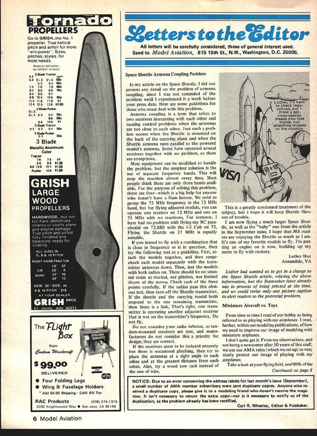
Space Shuttle Antenna Coupling Problem
In my article on the Space Shuttle, I did not present any detail on the problem of antenna coupling, since I was not reminded of the problem until I experienced it a week before your press date. Here are some guidelines for those who must deal with this problem.
Antenna coupling refers to two receivers interacting with each other and causing control problems when the antennas are too close. Just such a problem occurs when the Shuttle is mounted on the back of the carrying plane and the Shuttle antenna runs parallel to the powered model's antenna. Some have operated several receivers together with no problem, so there are exceptions.
Most equipment can be modified to handle the problem, but the simplest solution is the use of separate frequency bands. This will stop the reaction almost every time. Most people think there are only three bands available. For the purpose of solving this problem, there are four—which is a big help for anyone who doesn't have a Ham license. We tend to group the 75 MHz frequency with the 72 MHz band, but for flying adjacent models you can operate one receiver on 72 MHz and one on 75 MHz with no reactions. For instance, I have had no problem flying my RC parachutist on 72.080 MHz with the J-3 Cub on 75 MHz. Flying the Shuttle on 27 MHz is equally suitable.
If you intend to fly with a combination that is close in frequency or is in question, try the following test as a guideline:
- Attach the models together, then range-check each model separately with the transmitter antennas down.
- Test the models with both radios on. There should be no unusual noise at neutral, no glitches, and no limited throw of the servos. Check each of these points carefully.
- If the radios pass this obvious test, turn off the Shuttle transmitter. If the shuttle and the carrying model both respond to the one remaining transmitter, there is a link — one transmitter is operating another adjacent receiver that is not on the transmitter's frequency. Do not fly.
Do not consider your radio inferior; tandem-mounted receivers are rare, and manufacturers do not consider this a priority for design.
If the receivers seem isolated properly but there is occasional glitching, place the antennas at a right angle to each other and at the greatest distance possible. Also try a wood tow rack instead of one made of wire.
This is a greatly condensed treatment of the subject, but I hope it will keep Shuttle fliers out of trouble. I am now flying a much larger Space Shuttle as well as the "baby" one from the article in the September issue. I hope MA readers are enjoying the Shuttle as much as I am. It's one of my favorite models to fly. I'm putting an engine on it now, building up my nerve to fly with rockets.
Luther Hux Annandale, VA
Luther had wanted us to add the above information to the Space Shuttle article, but the September issue was already in the process of being printed; we could only revise one picture caption to alert readers to the potential problem.
Miniature Aircraft vs. Toys
From time to time I read of our hobby being referred to as playing with toy airplanes. I read, further, within our modeling publications, of how we need to improve our image of modeling with miniature airplanes.
I don't quite get it. From my observations, and not being a newcomer after 50 years of this stuff, we use our AMA rules (which we set up) to very nicely protect our image of playing with toy airplanes.
Take a look at your flying field, and 90% of the planes have a wing and stab that resemble a real airplane—little else that does. To upgrade the image of modeling miniature airplanes, just take an SE-5, AT-6, or even a P-51 and enter Masters Pattern... man, the toy airplanes will eat you alive.
Even in events like Scale, you just use scaled power in a breeze—and get bumped around just like real scale bumps—and then watch that upgraded, powerful, toy-like Scale miniature airplane give you fits.
Like it or not, we have created the image of toy airplanes with our rules, and that is just what we deserve. Fun, isn't it!
Eldon Wilson San Angelo, TX
How Propellers Work
There appear to be two principal schools of thought as to how propellers work, geometric pitch providing a handy dividing line between them. One holds that thrust is equal to the rate of change of momentum of the air upon which the propeller acts, and that the effective pitch must fall short of the ideal (geometric) pitch to the extent of the various losses resulting from this exchange. The other holds that, as a lifting surface that happens to rotate, the propeller can and does exceed geometric pitch.
In the first case, impetus is seen as a reaction to air thrust rearward by a vane; in the second (at least partially) by the drawing forward due to lift forces of the kind we commonly associate with a wing.
I would like to communicate with anyone who has ideas or evidence to support either of these views, or any qualifications to the manner in which I have attempted to describe them.
Richard Miller 1368 Rock Springs Rd. Escondido, CA 92026
Some interesting points will come out here, no doubt. Please communicate directly with Mr. Miller.
Baker's B-25
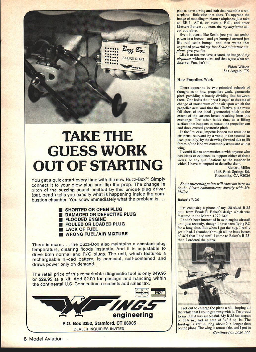
I'm enclosing a photo of my .20-sized B-25 built from Frank B. Baker's design which was featured in the March 1979 MA.
I hadn't been interested in twin-engine aircraft until just recently, though I have been flying RC for a long time. But when I got the bug, I really got it bad. I thumbed through all the back issues of MA that I had until I came to Baker's B-25; then I ordered the plans.
I set out to enlarge the plans a bit—hoping all the while that I could get away with it. I'm proud to say that it was successful. My B-25 has a span of 53 1/8 in. and an area of 343.6 sq. in. The fuselage is 37 5/8 in. long, about 2 in. longer than on the plans. The wing is removable, and I put in a steerable nose wheel coupled to the ailerons. I use two OS .10s for power, with an Ace three-channel for guidance. She weighs in at 4 1/4 lb.
(Continued from page 8)
The color scheme (olive drab) and the plane's name and numbers were taken from a Squadron/Signal publication on the B-25. By sheer coincidence, the name on the plane happened to be my wife's name (Patricia Ann). Talk about running up some points—at least a hundred, I'd say!
The whole project took about three weeks to construct, then there was another four to five weeks of waiting for the wind to quit blowing. Finally, it was test-flown successfully on May 25, 1981. I'm proud to say it's a great flying machine and very realistic. By the way, that's Patricia Ann in the picture with her namesake.
Enjoy your magazine very much. Keep up the good work.
A. R. Kawczynski Duncan, OK
Jill Kittel and the Airchild
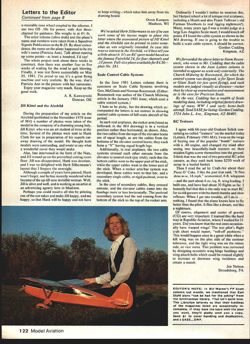
During the preparation of my article on the Airchild (published in the November 1979 issue of MA) a number of photos were taken of the model in the company of a charming young lady, Jill Kittel, who was an art student of mine at the time. Several of the photos were sent to Hank Clark for use in preparation of his superb cutaway drawing of the model. He thought both models were outstanding and wrote to say what a wonderful cover they would make.
Alas, fate interfered in the form of the Nats, and Jill wound up on the proverbial cutting room floor. Jill was disappointed, Hank was desolate, and I was so delighted with Herb Silbermann's layout that I forgave the oversight.
Although a couple of years have passed, Hank won't forget, and he has recently wondered what became of the up-till-now invisible woman. Well, Jill is alive and well and is working as an artist at an advertising agency here in Madison.
Perhaps you could resolve all this by printing one of the out-takes and make Jill happy, and me happy, so that Hank will be happy and not have to keep writing—which takes him away from his drawing board.
Owen Kampen Madison, WI
We've asked Herb Silbermann to see if he can work some of his layout magic to place this letter where the associated picture of Jill Kittel and the Airchild can be printed in color somewhat as was originally intended. In case this renews interest in the Airchild, here's a little about it: it's an RC sport model based on the famous Fairchild 24, for four channels and .23 power. Full-size plans available for $4.50—plan No. 281.
Scale Control Cable Systems
In the June 1981 Letters column there is comment on Scale Cable Systems involving Geo. McGinnis and Norman Rosenstock. (Editor: Rosenstock was author of the Church Midwing article in the January 1981 issue, which used a cable control system.)
I hate to be picky, but the drawing which accompanied the letters is not correct in showing control cable systems of full-scale aircraft of the period.
In such real airplanes, the rocker arm (listed as bellcrank in the MA drawing) is in a vertical position rather than horizontal, as shown. Also, the two cables from the tops of the elevator horns are of equal length, as are the cables from the bottoms of the elevator control horns; they each form a "V" having equal-length legs.
Additionally, in real airplanes, the two cable systems crossed each other en route from the elevator to the control stick (joy stick), such that the bottom cables went to the upper part of the stick, while the upper cables went to the lower part of the stick. When a rocker arm/bar system was developed, these cables went to that bar, and a secondary single cable, or rigid pushrod, went to the stick.
In the case of secondary cables, they crossed en route, and the elevator cables came into the fuselage more or less horizontally. The pushrod secondary system had the rod coming from the bottom of the stick to the top of the rocker arm.
Ordinarily I wouldn't bother to mention this, but I helped rebuild a lot of antique real airplanes, including a Heath and Frank Tallman's old Farman Shorthorn (a real rigging nightmare!). Many, many years ago I was a model judge at a large Los Angeles Scale meet; I would knock off points if I found the cable system as shown in the MA drawing. If one is going to the trouble to build a scale cable system, it should be correct.
Gordon Codding Kingman, AZ
We forwarded the above letter to Norm Rosenstock, who wrote to Mr. Codding that the cable system shown in the June Letters column is intended to appear as scale only externally. The Church Midwing by Rosenstock, for which the control system was designed, is for Sport Scale or Giant Scale (or just sport flying), and such models are judged visually at distance—rather than by close-up examination and measurement as is the case for Precision Scale.
By the way, Codding has a wealth of Scale modeling data, including original/factory drawings of many WW I and early home-built aircraft. Send SASE for a listing: Gordon Codding, 3724 John L. Ave., Kingman, AZ 86401.
RC Trainers
I agree with 66-year-old Graham Selick concerning so-called "trainers" on the market today (Letters, February 1981 MA). I was on the verge of buying one of the popular "bomb" trainers with a .40 engine, and changed my mind after seeing two beautifully built trainers on their maiden flights screw themselves into the ground. I think that was the end of two potential RC pilots, as they each took home $250 worth of scrap in a bushel basket.
Then I read the ad by Craft-Air about their Piece O' Cake. I like the part that said, "It flies slow—wk. 16 mph," economical, 6-ft. wingspan—and the part about 6 oz./sq. ft. wing loading. I built one, and have had about 30 flights so far. I honestly feel that this is the only way to start R/C for us old geezers with the dumb thumbs and slow reflexes. When I get into trouble, all I do is nothing. I found that the plane knows how to fly better than the pilot. It flies like a dream, not like a nightmare.
Of course, alignment and center of gravity (CG) are very important. I learned this the hard way in Republic Aviation, where I worked for 31 years. Did you know that the real ones occasionally have warped wings? The test pilot's flight card sheet would report, "roll-off problems." This would happen once in a great while when a left wing was on the plus side of the tolerance, and the right wing was on the minus side, or vice versa. This problem was corrected by designing eccentric wing hinge bushings and wing attach bolts which could be rotated slightly to increase or decrease wing incidence and obtain a match.
Joe Nelson Stroudsburg, PA
EDITOR'S NOTE: In Bill Warner's FF Scale column last month, we mentioned that Earl Stahl plans "can be had for the asking" from the Smithsonian library. That isn't quite true. The Librarian informs us that their holdings of the magazines listed are occasionally incomplete. If they have the issue with the plan you want, they'll gladly send you a copy. Send $1 to cover handling and duplication, and a SASE.... DRP
Transcribed from original scans by AI. Minor OCR errors may remain.

