
Canard Controversy
I appreciated Charles A. Bair, Jr.'s article entitled "The Case for the Canard." However, he neglected to point out one of the most important aerodynamic cases against the canard. That is that the forward mounted stabilizer, which must operate at a higher lift coefficient than the wing, produces downwash. The downwash affects quite a large portion of the center section of the main wing and reduces its L/D measurably.
Also, if I remember my Aero. Engineering lectures properly, I believe the canard is less sensitive to a wider range of center of gravity movement. This, of course, is an advantage for the canard, especially if you have to carry a "shifty" cargo like, say, a crop duster might.
Jim Noffsinger, AMA 95919 Lynchburg, VA
I would like to offer some comments about the article, "The Case for the Canard." Although Mr. Bair is somewhat dismayed by the fact that engineers haven't done more with the canard configuration, he should consider the following:
- The canard is not well suited to handling the powerful negative moment produced by flaps. (The SAAB SF37, being a delta, has no flaps.) In a conventional configuration (tail aft) the flaps produce a sizeable downwash increment which loads the horizontal tail to produce a favorable moment to balance that of the flap.
- Stability varies pretty much as the square of the tail moment arm about the CG. In the case of the canard the directional stability is therefore greatly reduced since the distance from the CG to the fin is very small by comparison.
- The long forebody is destabilizing in both pitch and yaw.
Real aircraft are designed with one criterion paramount above all others... safety. His comments regarding the desirability of placing the CG aft of the center of pressure of the wing on a conventional aircraft are absurd. Such an arrangement provides for no recovery from a stall, produces dynamic instability and makes the airplane extremely difficult to fly.
Finally, he should review his French.... canard means "duck" in French. The canard configuration is so named because it resembles a duck with its long outstretched neck and broad bill.
Bradford W. Powers, AMA 66044 San Diego, CA
Mr. Powers is a former Senior Design Engineer, Preliminary Design, with Convair. Both Mr. Bair, author of the "Case for the Canard" and Mr. Sanders, codesigner of the Zonker with Mr. Bair, are prominent aeronautical engineers. Both of them respond below to Mr. Powers' and Mr. Noffsinger's comments. As to the correct definition of the word "canard" in a caption our own French dictionary shows us on firm ground.
Reader letters give everyone an opportunity for feedback and a better insight into the world of aerodynamics. Actually, very little in aerodynamics is black and white. One can find advantages and disadvantages for any configuration, canard or otherwise. A designer makes trade-offs to try and get the best performance for the intended use of his design. Which is better: an F-4, or a Diamant sailplane?
In answer to Jim Noffsinger, the canard stabilizer indeed operates at a higher lift coefficient. That is a requirement for a stable airframe. Also the forward stabilizer does immerse the center section of the wing in downwash. The L/D of the wing most probably will decrease, but performance of the aircraft as a whole (wing-body-tail) is the important concept. With both the wing and stabilizer lifting (canard), the aircraft L/D should be higher than an equivalent conventional aircraft where the wing lifts and the tail pushes down. The big question is, "How much is the difference?" Each design will have different effects and must be analyzed or wind tunnel tested to find the relative magnitudes of the differences. We measured an L/D of 13 on one canard design in a wind tunnel test. Sailplanes are 19 and above, while fighters are significantly lower at 3 or 4.
As far as CG range, the same equations and design principles govern both conventional and canard configurations. Results are the same for either type.
In answer to Mr. Powers, flaps can develop a powerful nose down moment depending on deflection, size, and placement on the wing. Flaps are generally used to decrease takeoff and landing distances, and to help keep jet engines at a higher thrust level during landing. Airplanes with low wing loadings (general aviation and model aircraft) handle very nicely without flaps and could benefit from a canard configuration. The canard can also handle flaps within the limits of its control power.
In the stability equations, directional stability depends on what is called the vertical tail volume (product of vertical tail area times distance from the CG). When the CG is moved, the stability varies linearly with the distance, not the square of the distance. This does not present a problem to the canard even if that distance to the CG is as small as half that on a conventional design. The solution is to increase a dimension of the vertical tail to keep the tail volume unchanged and retain the same degree of directional stability.
In general, anything in front of the CG (including the prop) has a destabilizing influence. A canard simply has more destabilizing surface area in front of the CG. Using stability equations, the vertical tail volume is sized to provide the required degree of directional stability, and the CG is located forward to provide sufficient longitudinal stability.
If Mr. Powers will take a close look at his longitudinal static stability equation, he will find that as he increases horizontal tail volume, the aircraft neutral point moves rearward (conventional airplane). It can even move to the trailing edge of the wing. The center of pressure on a symmetrical wing is located very near the quarter chord. With the neutral point on the trailing edge, the CG could be located at the 3/4 chord which would provide a 25% static margin (quite stable) while having the CG behind the center of pressure. Some model designs have flown this way for quite some time to take advantage of an upload on the tail rather than the normal download. These airplanes are quite stable, even through a stall. The uploaded tail provides the stabilizing influence.
Regarding the word "canard," Cassell's New French Dictionary lists several meanings, among which are: duck, drake, false news, hoax. A canard resembles a duck with its long outstretched neck, but also many people (especially in the Wright Brothers' time) don't believe canards fly—hence either definition fits well. The Frenchman who originated the term would be the best source for accuracy; however, in his absence the choice is yours.
Milt Sanders Fairborn, OH
Milt Sanders was kind enough to answer the questions about my canard article while I was on a business trip. Here are a few of my own comments:
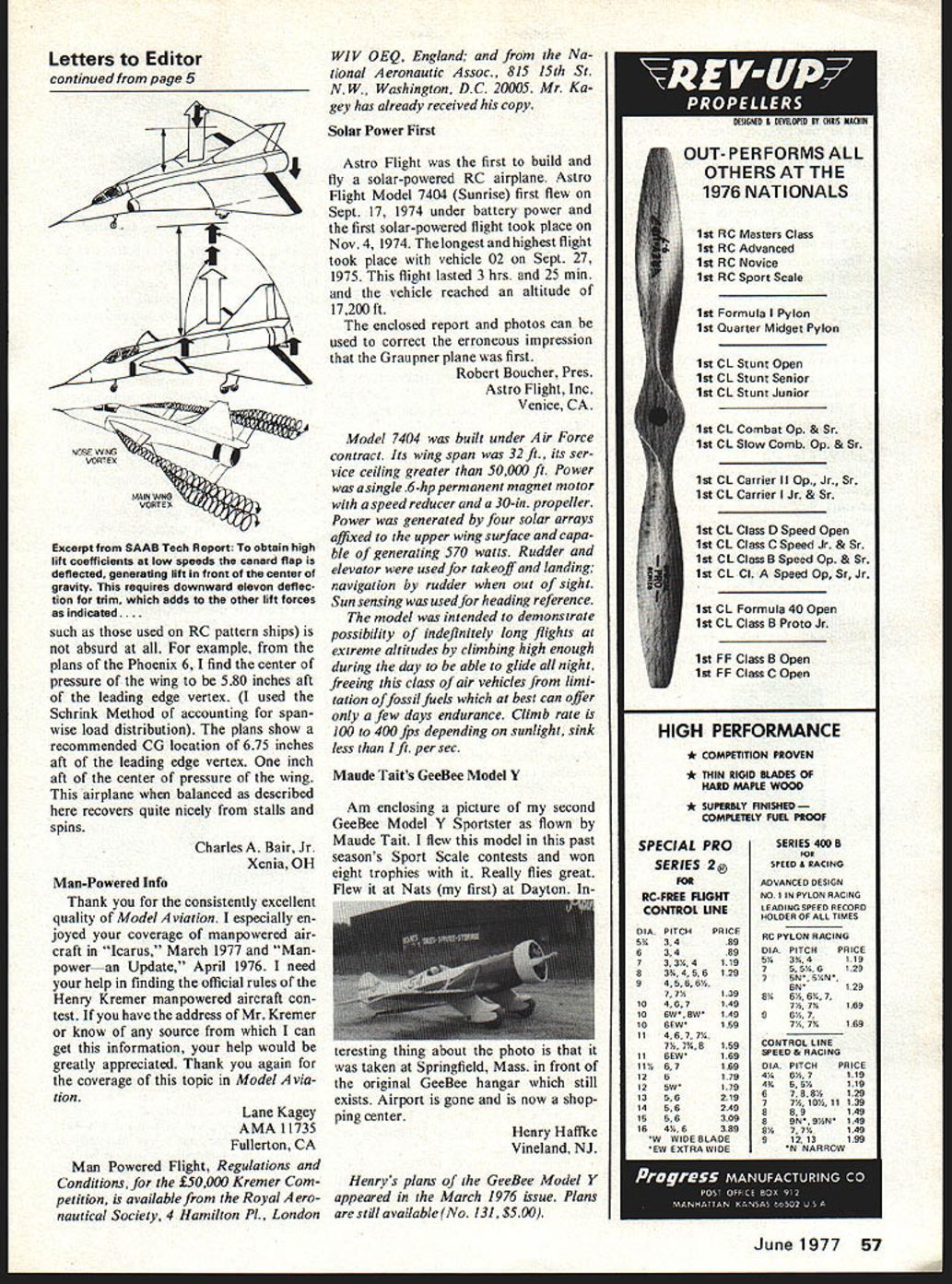
In response to Jim Noffsinger's letter, I would like to add that the canard downwash and tip vortex can interact advantageously with the wing flow field. (See attached information from SAAB.)
In response to Bradford Powers' letter:
- The SAAB Viggen does have elevons on its delta wings, which function as flaps in the landing configuration (both sides deflect down). A reference from SAAB is attached.
- The formula for yaw stiffness (Cnβ) contributed by the vertical stabilizer alone is
Cnβ = a_v S_v l_v / S_w b_w · η_t (1 − dσ/dβ)
where:
- a_v = lift curve slope of the vertical stabilizer.
- S_v = area of the vertical stabilizer.
- l_v = distance from the CG to the center of pressure of the vertical stabilizer.
- S_w = area of the wing.
- b_w = span of the wing.
- η_t = tail efficiency.
1 − dσ/dβ = a correction for sidewash.
The point to be made here is that l_v is a linear term. It is not squared.
- Bradford Powers is correct. However, a canard airplane can be designed to be stable in both pitch and yaw. One must consider the entire airplane, not just the destabilizing components.
Placing the center of gravity of a conventional airplane aft of the center of pressure of the wing (25% mean aerodynamic chord for an untwisted symmetric wing such as those used on RC pattern ships) is not absurd at all. For example, from the plans of the Phoenix 6, I find the center of pressure of the wing to be 5.80 inches aft of the leading-edge vertex. (I used the Schrenk Method of accounting for spanwise load distribution.) The plans show a recommended CG location of 6.75 inches aft of the leading-edge vertex — one inch aft of the center of pressure of the wing. This airplane, when balanced as described here, recovers quite nicely from stalls and spins.
Charles A. Bair, Jr. Xenia, OH
Transcribed from original scans by AI. Minor OCR errors may remain.

