
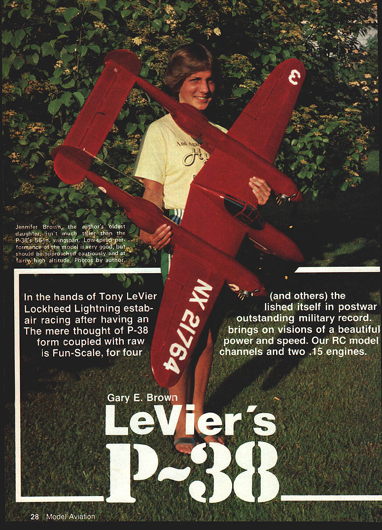
LeVier's P-38
Gary E. Brown
In the hands of Tony LeVier (and others) the Lockheed Lightning established itself in postwar air racing after an outstanding military record. Our RC model is fun-scale: four channels and two .15 engines. To be a really good flier the model must be built lightly; ready-to-fly weight should not exceed 4-1/2 lb.
Introduction and history
Even casual acquaintances with fighter aircraft can easily picture this off-the-beaten-design-path bird. In 1937 Lockheed designers Hall Hibbard and Clarence “Kelly” Johnson produced the distinctive lines of the P-38 in response to Army specifications for a high-performance pursuit fighter. Lockheed won the competition and built the first XP-38.
Notable and, for 1937, radical features included:
- Twin-boom layout with a central pod (nacelle) for the pilot and armament
- Tricycle landing gear, made practical by the pod and lack of engine in the nose
- Twin turbo-supercharged V-1710 Allison liquid-cooled engines with counter-rotating propellers to cancel torque
- Nose-mounted guns in the pod, firing straight ahead
Early in 1939 the XP-38 crashed during a speed-record attempt and had flown only about 12 hours; nevertheless the Army ordered 13 aircraft. During WWII the P-38 served as a fighter, bomber escort and one of the most successful photo-reconnaissance aircraft, using superior speed to outrun adversaries.
After WWII the National Air Races reopened (1946). War-surplus fighters dominated the races. Tony LeVier, a Lockheed test pilot and experienced racer, campaigned a refined P-38L in the Nationals. LeVier’s P-38L had superchargers and trailing-edge intakes removed and faired over, with increased fuel capacity. Some racing results:
- 1946: 2nd place, Thompson Trophy Race, average 370.2 mph
- 1947: 5th place, Thompson Trophy Race, average 357.5 mph
- 1947: 1st place, Sohio Trophy Race, average 360.9 mph
Construction
The project's goal is a lightweight built-up twin-engine fun-scale model with good flying characteristics and eye appeal. Keep the structure light; plan on no more than 4-1/2 lb ready-to-fly. Use two identical engines from the same manufacturer and ensure both run flawlessly before attempting any flight.
Notes from the build:
- The original model required added lead to each tail boom to correct nose-heaviness; if desired, sheet tail surfaces can be used instead of built-up to gain tail weight and save time.
- All subassemblies should be cut out and prepared before final assembly to ensure accuracy and alignment.
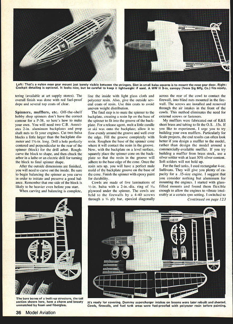
Photos / workshop notes
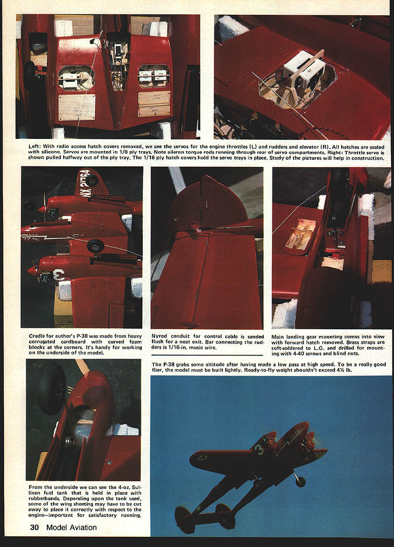
- Servos: With radio access hatch covers removed you can see servos for engine throttles (left) and rudders/elevator (right). All hatches are sealed with silicone. Servos are mounted in 1/8-ply trays; aileron torque rods run through the rear of the servo compartments. 1/16-ply hatch covers hold servo trays in place.
- Cradle: A cradle made from heavy corrugated cardboard with curved foam blocks at the corners is handy for working on the underside of the model.
- Control runs: Nyrod conduit for control cable should be sanded flush for a neat exit. The bar connecting the rudders is 1/16-in. music wire.
- Main gear: Brass straps are soft-soldered to the landing gear and drilled for mounting with 4-40 screws and blind nuts.
- Fuel tank: A 4-oz Sullivan tank shown held with rubber bands; depending on tank used some wing sheeting may need cutting for correct placement relative to the engine.
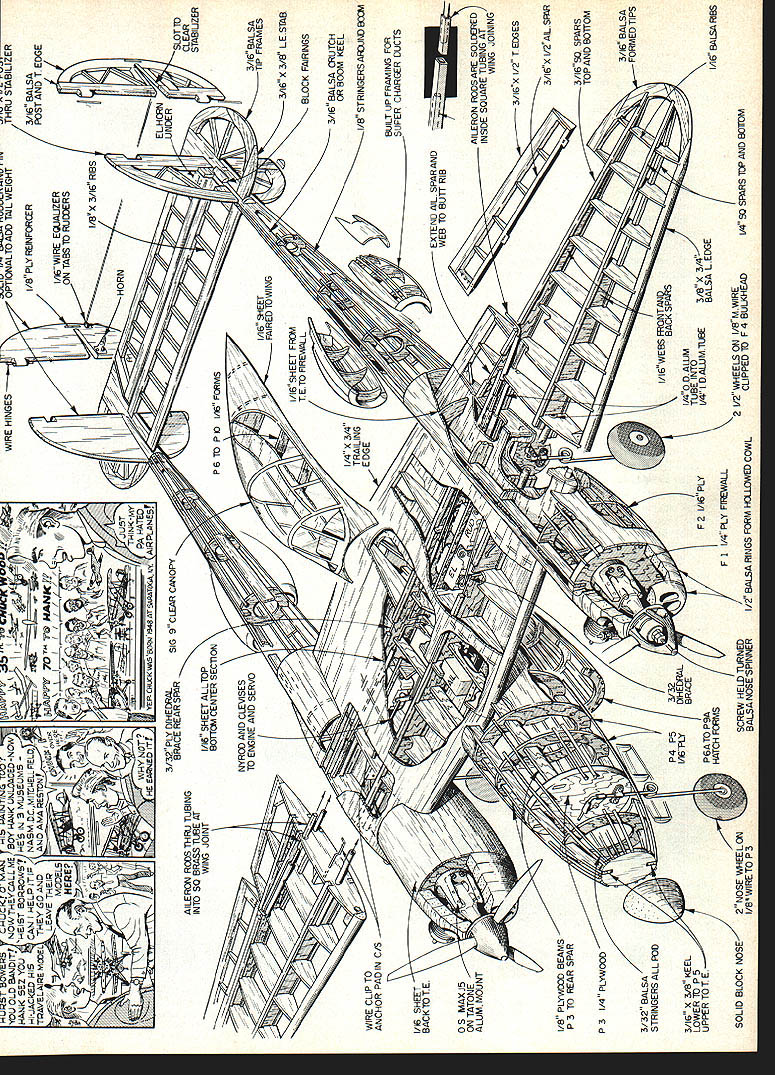
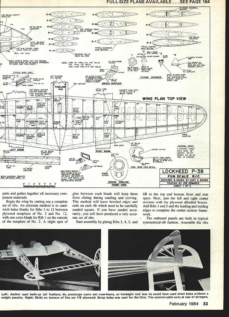
Wing
The wing is in three parts: center section and two outboard panels. The build centers on the center section front and rear spars; accuracy and alignment are critical because all flight and landing loads tie into this unit.
Key construction points:
- Join halves using 1/4-in. o.d. brass tubing at the front spar and 3/16-in. o.d. brass tubing at the rear spar. The brass tubing telescopes into aluminum tubing of the same i.d. epoxied between top and bottom spars.
- Aileron torque rods pass through the wing joint via square brass tubing of the same i.d./o.d. (5/16-in. o.d. in outboard panels).
- Outboard panels include 5/16-in. music wire hooks that snap through a hole in a 3/32-in. plywood plate mounted in the wing root. Hooks are engaged/released by reaching through main gear openings with a screwdriver.
- Begin by cutting a complete set of ribs. An alternate method: sandwich balsa blanks for Ribs 3–12 between plywood templates for Nos. 2 and 12 (with an extra blank for Rib 1). Glue spots between blanks keep them from shifting while sanding. Sand beveled edges square for accurate ribs.
- Glue Ribs 3, 4, 5, and 6B to top and bottom front and rear spars. Join left and right center sections with plywood dihedral braces. Add Ribs 1 and 2 and leading and trailing edges to complete center section framework.
- Outboard panels: assemble ribs, glue front and rear spars, sheet top surfaces. Install aileron torque tubes and any control tubing before sheeting undersurfaces. Sand, fillet joints and check dihedral and alignment before final covering.
- Join halves: cut shims to space aluminum tubes evenly between spars; make sure the aluminum tubes in front and rear spars are perfectly parallel horizontally and vertically. Join outboards to center while epoxy is wet with brace tubes in place for exact alignment.
- Add 1/8-in. plywood beams that carry the formers for the pod forward of the wing leading edge to the 3/16-in. plywood bulkhead that mounts the nose wheel. Incorporate 1° positive wing incidence by setting the beams 1° below centerline of the airfoil before epoxying to plywood dihedral braces.
- Sheet the wing center section with 1/16-in. balsa except for radio hatches. Wing servo hatch covers are cut from 1/16-in. plywood and held with four corner screws.
- Ailerons are built as separate units. Before covering and painting, add about 1/4-in. of washout in the tips (see Covering and finish).
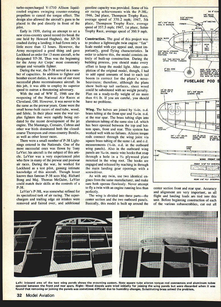
Booms
- Assemble 3/16-in. keel and backbone pieces over the plans. Mount Formers 5–10 and firewall. If desired, angle each firewall outward a couple of degrees to provide engine out-thrust (may aid control with one engine out).
- Glue all stringers from Formers 6–10 and notch ends to accept forward flush 1/16-in. sheeting. Spruce stringers were used but balsa stringers are recommended now to save weight.
- Glue booms to wing center section, ensuring booms are parallel horizontally and vertically and set to 1° positive wing incidence. Add remaining formers to top and bottom of the wing.
- Drill landing gear mounting holes for main gear in Former 4 before gluing it in place. Sheet booms with 1/16-in. balsa forward of Former 6.
- Add small fillets where booms and pod join wing—Spackling compound or Sig Expoxolite work well.
- Engines may be mounted horizontally or in another orientation; mount fuel tanks so their centerlines are just below carburetor needle valves for reliable feeding. Fuel-proof tank area and firewall with epoxy or polyester resin.
- Air intakes are built up of 1/16-in. balsa pieces between the boom stringers to provide a gluing base. Add intakes after covering booms.
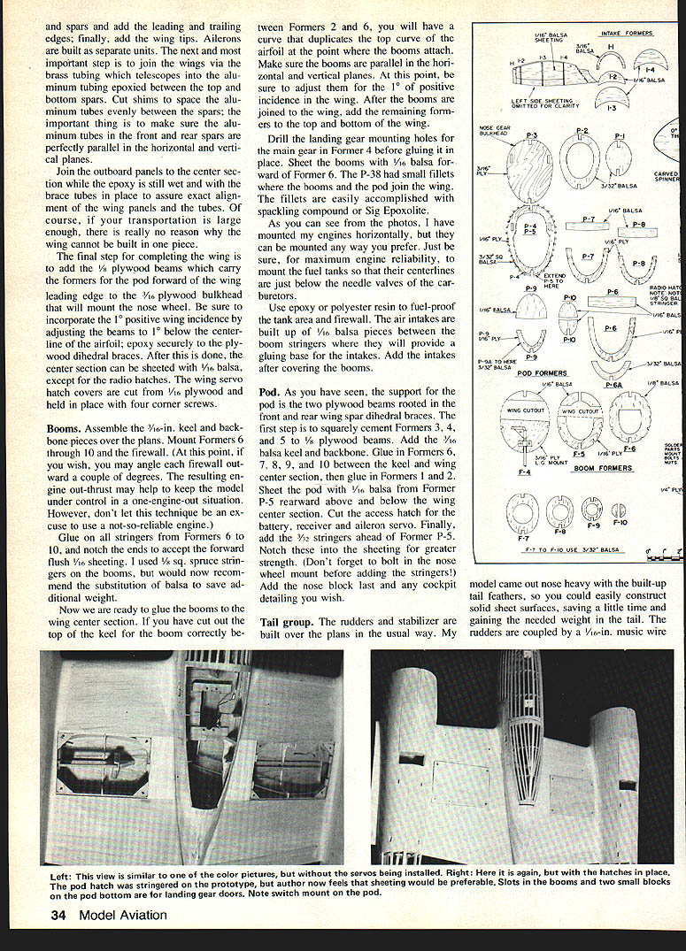
Pod
- Pod support is provided by two plywood beams rooted in the front and rear wing spar dihedral braces.
- Squarely cement Formers 3, 4 and 5 to 1/8-in. plywood beams. Add 1/16-in. balsa keel and backbone. Glue in Formers 6–10 between keel and wing center section, then glue in Formers 1 and 2.
- Sheet pod with 1/16-in. balsa from Former P-5 rearward above and below wing center section. Cut access hatch for battery, receiver and aileron servo.
- Add 3/32-in. stringers ahead of Former P-5, notched into sheeting for strength. Bolt in nose wheel mount before adding these stringers. Add nose block and any cockpit detailing last.
Tail group
- Rudders and stabilizer are built over plans in the usual way. The model ran nose-heavy with built-up tail surfaces; solid sheet surfaces can be used instead to save time and add needed tail weight.
- Rudders are coupled by a 1/16-in. music wire pushrod which avoids extra internal cable work. Alternatively, run cables to both rudders and synchronize them if you prefer the cleaner look.
Covering and finish
- Carefully sand the entire framework before covering. Silkspan (medium weight) was used on the original.
- After wing panels are covered and before painting, introduce about 1/4-in. washout in the tips: hold the framework over steaming water for several minutes, twist the tips, and hold slightly more twist until the covering dries. Ensure equal washout in each tip; re-steam if needed.
- Other lightweight finishes can be used in place of silkspan.
- Lettering: MonoKote Trim was used for some lettering; "Tony LeVier" on the pod was hand-lettered with brush and dope; “Fox of the Skyways” used transfer letters.
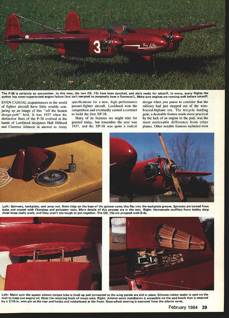
Spinners, mufflers, cowls, fuel tanks
Spinners:
- Off-the-shelf spinners do not match P-38 contour. Use two C.P.C. Associates 2-in. aluminum backplates and matching prop shaft nuts.
- Cut two balsa blocks slightly larger than backplate diameter, 1-1/2 in. long. Drill a centered hole for the drill arbor, rough-carve and turn on a lathe or electric drill to final shape.
- Carve inside, balance as you go. Line inside with light glass cloth and polyester resin; coat outside with several thin coats of resin to avoid weight imbalance.
- Mate spinner to backplate: melt candle or ski wax onto the backplate as a release agent; fill the groove with resin; roughen the base of the cone; place cone on backplate while resin is level to create a male mold on the cone’s base. Finish with epoxy paint.
Cowls:
- Constructed from five laminations of 1/2-in. balsa with a 2-in.-dia. 1/8-in. plywood ring under spinner.
- Cowls are attached to firewalls by a 4-40 screw through a 1/4-in. ply bar epoxied diagonally across the rear of the cowl into blind nuts in the firewall. Screws are installed/removed through the air intakes to avoid external fasteners.
Mufflers:
- Mufflers fabricated from K&S sheet brass and tubing fit O.S. .15s. For custom brass mufflers use silver solder with at least 30% silver content; soft solders will not hold up.
Fuel tanks and engine mounts:
- Rectangular 4-oz Sullivan tanks give adequate capacity for .15 engines.
- Use aluminum engine mounts. Glass-filled mounts can be too flexible and allow excessive vibration at certain RPMs; aluminum prevents that.
Flight characteristics and handling
- Surface movements (approximate):
- Rudders: 3/8 in. both ways
- Ailerons: 1/4 in. both ways
- Elevator: 5/16 in. both ways, with a bit of up trim to start
- Aileron response is positive but roll rate is slow (like the full-size aircraft). In the author’s model ailerons and rudders needed no trim adjustments; elevator required some up-trim to offset nose-heaviness.
- Landings are not Cub-like, but full throttle is not required. On first flights make several landing approaches well before fuel runs low to learn sink rate. Keep the nose level or slightly down until just before touchdown, then flare slightly.
- Low-speed testing (at safe altitude) shows the model hangs without stalling surprisingly well.
- Sync both engines and make sure they run perfectly before takeoff. The author never experienced an engine failure in many flights and does not recommend attempting a flameout.
If you’ve wanted to try a twin but dislike boxy add-an-engine designs, this racy P-38 is rewarding both on the ground and in the air.
Transcribed from original scans by AI. Minor OCR errors may remain.

