

Life with the Monsters
Kirby Crawford
The Bealton Scene
The scene is a sunny fall morning out in the Virginia countryside at the DC/RC Bealton scale contest last September. The aircraft is a 26-lb. Curtiss Gulfhawk with a 1.9 cu. in. chainsaw engine up front swinging a 22-in. prop. You can hear the engine unload as the big orange biplane descends in a final turn onto the runway heading. The smoke switch is flipped on and billows of blue smoke pour from the big exhaust pipe. The nose is pulled up slightly then full ailerons are applied. The big biplane does a graceful 1930s vintage roll with airshow smoke. You can hear the seasoned scale judges say, "Wow."
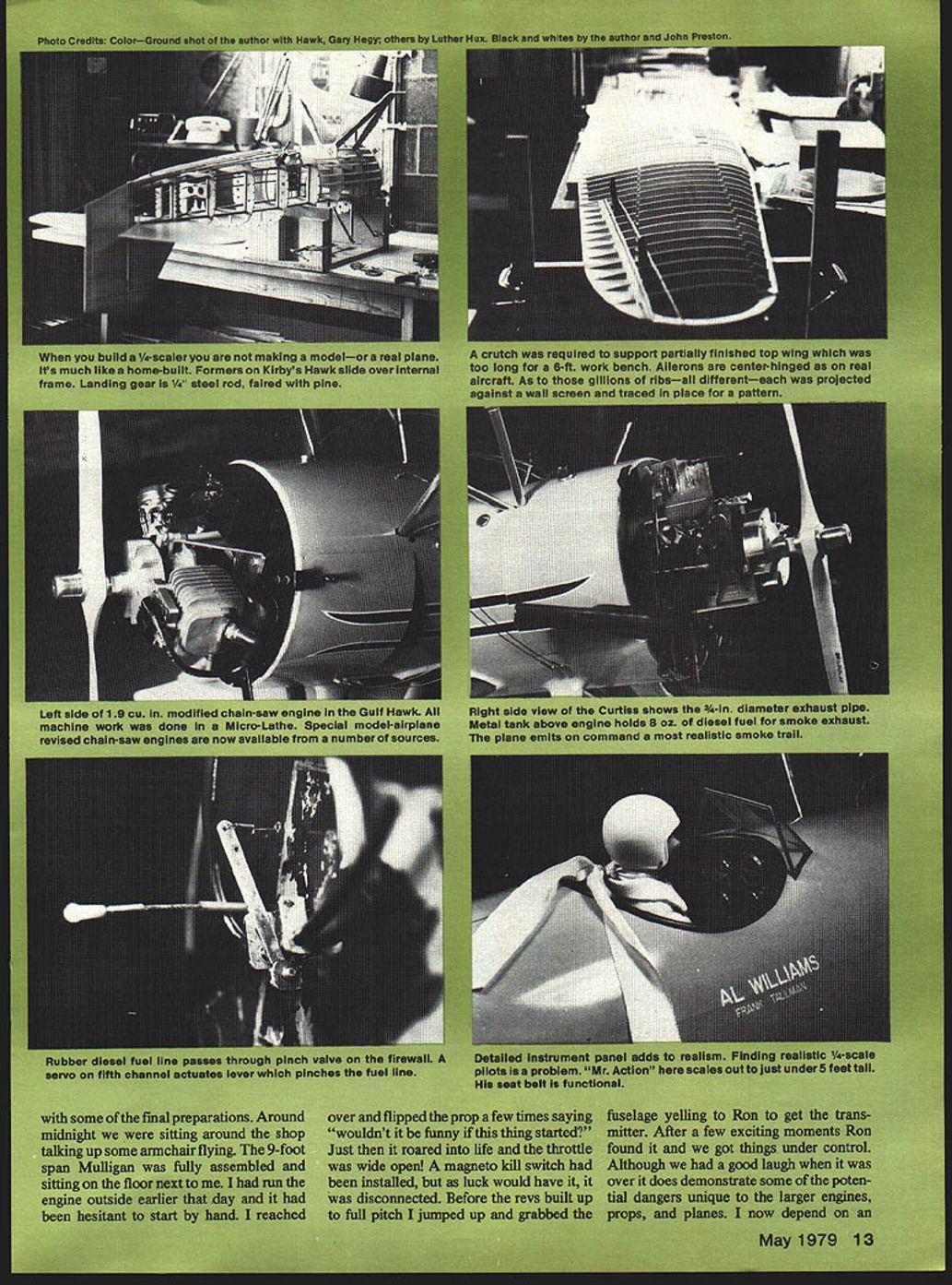
All this started for me several years ago when I was inspired by an article written by Dick Phillips in one of the popular model magazines. In that article Dick briefly described the factory modifications to the 1.9 cu. in. Quadra engine which was scheduled for production for model aircraft use. He also described a J-3 Cub project to handle the large engine. Having some knowledge of metal lathe work, I felt that the engine modifications could be done on an inexpensive hobbyist's lathe. This has proven to be true as all of my engine work has been done on a Taig Micro-lathe.
Engine selection and modification
I like to do things in the hobby that are innovative and challenging. I was fascinated by the idea of modifying a relatively inexpensive off-the-shelf chainsaw engine to make it fly. Some time was spent in hardware stores pecking inside of chainsaws, checking for such things as general engine layout, carburetor and exhaust location, and how it could be adapted to firewall mounting. Several makes were found to be usable. I finally decided on the 1.6 Homelite XL for two reasons. Firstly, a friend who has used chainsaws for years recommended Homelite; and secondly, a local hardware chain had them on sale for $65.00.
So one Saturday morning I went out and bought one, took it home to the shop and proceeded to remove all those parts that were not needed for flying. I must say that I had serious second thoughts about this whole thing while sawing away at this brand-new chainsaw with a hacksaw. The modification was in fact quite simple and successful. Now that several ready-to-fly engines of this type are on the market, the modeler can get into large-scale flying without having to develop his own engine.
The Homelite has proven to be a good performer. With stock magneto ignition, 20:1 gas/oil mix and a 20 x 5 Kolb Korp prop it will pull a 24-lb. aircraft through large aerobatic maneuvers with speed.
Choosing a test bed: Mr. Mulligan
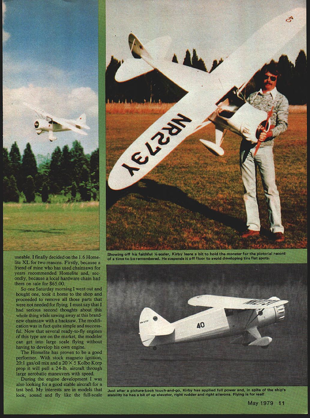
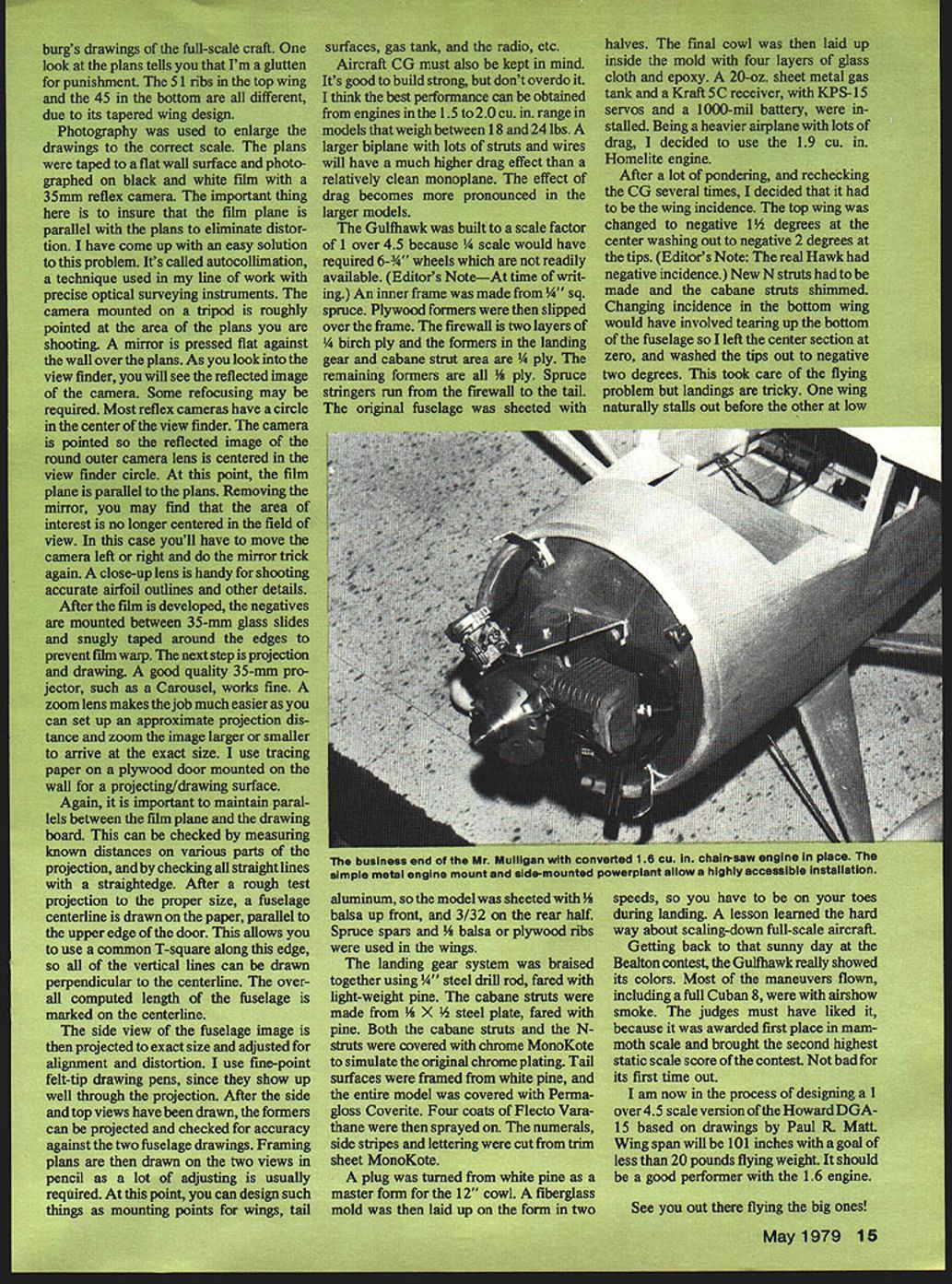
During the engine development I was also looking for a good stable aircraft for a test bed. My interests are in models that look, sound and fly like the full-scale variety. One problem with the larger engines is getting them inside of scale cowlings. The nose on Mr. Mulligan in the ads appeared to fit all of my requirements. I called Bud in Two Harbors and asked him what the diameter and depth was on the Mulligan cowl. He said about 12 inches diameter by 6 inches deep. That was plenty of room so I ordered one.
The kit was brought to one of our Northern Virginia Radio Control club meetings for show-and-tell. It took two of us to hold up the plans so all could see. Quarter-scale airplanes are not only big, but they generate tremendous interest. During the months of building that followed my basement became a local curiosity with club members, friends and their families visiting regularly to check on progress.
Modifying the kit for the larger engine
A lot of time was spent designing the modifications to the kit for the larger engine. Problems to be considered begin with the additional four pounds of engine weight in the nose. Structural integrity must be increased to handle heavier engine vibration and greater G forces in flight.
Key structural changes included:
- Firewall: 3/8" birch ply laminated with a layer of 1/8" aircraft ply.
- Longerons and stringers: made from pine or spruce using the original balsa dimensions.
- Formers in the landing gear area: 1/4" or 3/8" ply in place of 1/8" lightweight ply.
- Landing gear: heavier music wire for struts and an 18-oz. galvanized sheet-metal gas tank fabricated and installed on the landing gear mounting plate over the CG.
- Cabin sides: laminated balsa and light ply replaced with 1/4" birch ply.
- Tail surfaces: pine replaced all balsa construction.
- Wing reinforcement: balsa ribs replaced with 1/8" aircraft ply in high-stress areas (wing roots and strut attachment locations); lots of gussets and webbing used throughout.
These engines have a diaphragm fuel pump in the carb so fuel draw is no problem. A Kraft 5C receiver, with KPS-15 servos, was installed in the rear of the cabin area.
The building technique in these larger models is quite different than what we're used to. I remember having a 1/4" electric drill and both hands up to the elbows inside the cabin area to drill some holes.
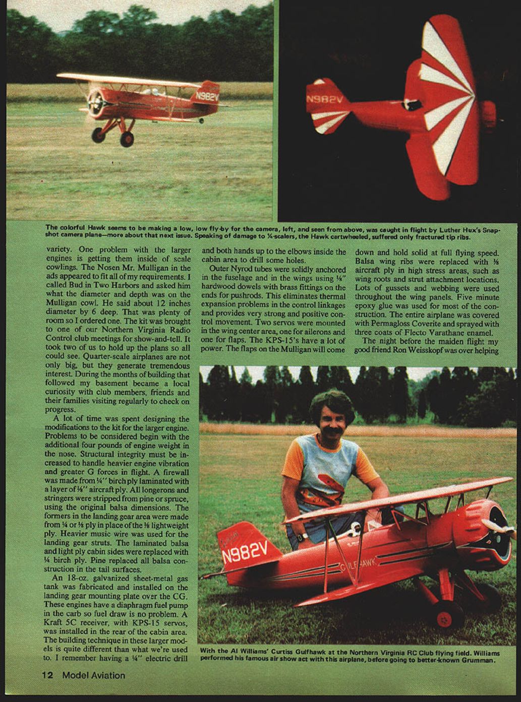
Outer Nyrod tubes were solidly anchored in the fuselage and in the wings using 1/4" hardwood dowels with brass fittings on the ends for pushrods. This eliminates thermal expansion problems in the control linkages and provides very strong and positive control movement. Two servos were mounted in the wing center area, one for ailerons and one for flaps. The KPS-15s have a lot of power. The flaps on the Mulligan will come down and hold solid at full flying speed. Five-minute epoxy glue was used for most of the construction. The entire airplane was covered with Permagloss Coverite and sprayed with three coats of Flecto Varathane enamel.
A late-night scare and safety lessons
The night before the maiden flight my good friend Ron Weisskopf was over helping with some of the final preparations. Around midnight we were sitting around the shop talking up some armchair flying. The 9-foot-span Mulligan was fully assembled and sitting on the floor next to me. I had run the engine outside earlier that day and it had been hesitant to start by hand. I reached over and flipped the prop a few times saying, "Wouldn't it be funny if this thing started?" Just then it roared into life and the throttle was wide open!
A magneto kill switch had been installed, but as luck would have it, it was disconnected. Before the revs built up to full pitch I jumped up and grabbed the fuselage yelling to Ron to get the transmitter. After a few exciting moments Ron found it and we got things under control. Although we had a good laugh when it was over, it does demonstrate some of the potential dangers unique to the larger engines, props and planes. I now depend on an external choke lever to kill a runaway engine on the ground. A 20° prop turning 7,000 rpm can do a lot of damage. Safety should always be the first consideration in designing and flying these biggies. The throttle control system must be goof-proof. I use steel plate for the throttle control arm on the carb; it is bolted to the butterfly shaft and silver-soldered in place. Heavy-duty steel cable is used for throttle control linkage.
Maiden flight and handling
Being an experimental aircraft and engine, the maiden flight was not widely announced, both for safety reasons and, perhaps, to save face in case it was a complete flop.
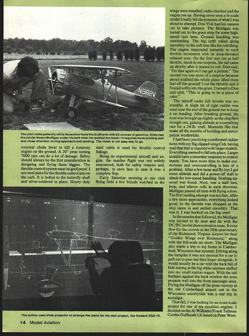
Early Saturday morning at our club flying field a few friends watched as the wings were installed, radio checked and the engine run up. Having never seen a 1/4-scale model I really felt the pressure of what I was about to attempt. Don Vick had his camera out to take pictures. The Mulligan was taxied out to the grass strip for some high-speed taxi tests. Ground handling was outstanding. The big craft rolled along smoothly on the soft tires like the real thing. The engine responded instantly to each throttle movement with its deep-throated exhaust note.
On the first taxi run at half throttle, much to our surprise, the tail came up shortly after it started to roll. Don said, "Do that again so I can get a picture." The second run was more of a surprise because about midfield the whole plane lifted three feet off the ground! I cut the throttle and it floated softly into the grass. I turned to Don and said, "This is going to be a piece of cake."
The takeoff under full throttle was uneventful. A slight bit of right rudder was used near the end of the ground run to keep it on heading. After breaking ground, the nose was brought up slightly as the ship flew straight out, gaining altitude at a surprising rate for a 24-lb. craft. Moments like that make all the months of building and anticipation worthwhile.
I had been practicing coordinated rudder turns with my Sig clipped-wing Cub, having read that this is required with larger models. Everything seemed to fall into place. Larger models have a smoother response to control inputs. You have more time to make corrections and overcontrolling is less of a problem. After a few turns and fly-bys I got some altitude and did a power-off stall to check for low-speed handling. Nothing unusual was found. Next was a stall turn, loop, and aileron rolls in each direction. Mulligan passed all tests with flying colors. The first landing attempt was too fast. After a few more approaches, everything looked good, so the throttle was chopped as the ship came in and it settled smoothly. That was it. I was hooked on the big ones!
Demonstrations and road trips
In the months that followed, the Mulligan was invited to fly near and far with the DC/RC model demonstration team. It even flew for the crowds at the 50th anniversary of the Richmond, Virginia Airport for their "Golden Wings over Richmond" along with the full-scale air show. The Mulligan also made a trip to my home in Cumberland, Wisconsin that summer. Driving along the turnpike it was not unusual for a car to pull out to pass but then linger alongside. It would usually be a car with the back full of kids staring at the big white airplane stuffed into my small station wagon. With the tail feathers against the back window the nose projects well into the front passenger area. Flying the Mulligan off the grass runway at the old Cumberland airport out in the Wisconsin countryside was a real trip in nostalgia.
Gulfhawk: scaling and construction
That fall, I was looking for an exact scale project for one of my modified engines. I decided on the Al Williams/Frank Tallman Curtiss Gulfhawk 1A based on Peter Westburg's drawings of the full-scale craft. One look at the plans tells you that I'm a glutton for punishment. The 51 ribs in the top wing and the 45 in the bottom are all different, due to its tapered wing design.
Photography was used to enlarge the drawings to the correct scale. The plans were taped to a flat wall surface and photographed on black-and-white film with a 35-mm reflex camera. The important thing here is to ensure that the film plane is parallel with the plans to eliminate distortion. I have come up with an easy solution to this problem. It's called autocollimation, a technique used in my line of work with precise optical surveying instruments.
The camera mounted on a tripod is roughly pointed at the area of the plans you are shooting. A mirror is pressed flat against the wall over the plans. As you look into the viewfinder you will see the reflected image of the camera. Some refocusing may be required. Most reflex cameras have a circle in the center of the viewfinder. The camera is pointed so the reflected image of the round outer camera lens is centered in the viewfinder circle. At this point, the film plane is parallel to the plans. Removing the mirror, you may find that the area of interest is no longer centered in the field of view. In this case you'll have to move the camera left or right and do the mirror trick again. A close-up lens is handy for shooting accurate airfoil outlines and other details.
After the film is developed, the negatives are mounted between 35-mm glass slides and snugly taped around the edges to prevent film warp. The next step is projection and drawing. A good-quality 35-mm projector, such as a Carousel, works fine. A zoom lens makes the job much easier as you can set up an approximate projection distance and zoom the image larger or smaller to arrive at the exact size. I use tracing paper on a plywood door mounted on the wall for a projecting/drawing surface.
Again, it is important to maintain parallels between the film plane and the drawing board. This can be checked by measuring known distances on various parts of the projection, and by checking all straight lines with a straightedge. After a rough test projection to the proper size, a fuselage centerline is drawn on the paper, parallel to the upper edge of the door. This allows you to use a common T-square along this edge so all of the vertical lines can be drawn perpendicular to the centerline. The overall computed length of the fuselage is marked on the centerline.
The side view of the fuselage image is then projected to exact size and adjusted for alignment and distortion. I use fine-point felt-tip drawing pens, since they show up well through the projection. After the side and top views have been drawn, the formers can be projected and checked for accuracy against the two fuselage drawings. Framing plans are then drawn on the two views in pencil as a lot of adjusting is usually required. At this point, you can design such things as mounting points for wings, tail surfaces, gas tank, and the radio, etc.
Aircraft CG must also be kept in mind. It's good to build strong, but don't overdo it. I think the best performance can be obtained from engines in the 1.5 to 2.0 cu. in. range in models that weigh between 18 and 24 lbs. A larger biplane with lots of struts and wires will have a much higher drag effect than a relatively clean monoplane. The effect of drag becomes more pronounced in the larger models.
The Gulfhawk was built to a scale factor of 1 over 4.5 because 1/4 scale would have required 6-1/2-inch wheels which are not readily available.
(Editor's construction notes)
- An inner frame was made from 1/4" sq. spruce. Plywood formers were slipped over the frame.
- The firewall is two layers of 1/8" birch ply and the formers in the landing gear and cabane strut area are 1/4" ply. The remaining formers are all 3/16" ply.
- Spruce stringers run from the firewall to the tail. The original fuselage was sheeted with aluminum, so the model was sheeted with 1/8" balsa up front, and 3/32" on the rear half.
- Spruce spars and 1/8" balsa or plywood ribs were used in the wings.
- The landing gear system was brazed together using 1/4" steel drill rod, faired with lightweight pine. The cabane struts were made from 5/32" x 1/2" steel plate, faired with pine.
- Cabane struts and N-struts were covered with chrome MonoKote to simulate the original chrome plating. Tail surfaces were framed from white pine, and the entire model was covered with Permagloss Coverite. Four coats of Flecto Varathane were then sprayed on. The numerals, side stripes and lettering were cut from trim-sheet MonoKote.
- A plug was turned from white pine as a master form for the 12" cowl. A fiberglass mold was then laid up on the form in two halves. The final cowl was then laid up inside the mold with four layers of glass cloth and epoxy.
- A 20-oz. sheet metal gas tank, a Kraft 5C receiver with KPS-15 servos and a 1000-ma battery were installed.
- Being a heavier airplane with lots of drag, I decided to use the 1.9 cu. in. Homelite engine.
After a lot of pondering, and rechecking the CG several times, I decided that it had to be the wing incidence. The top wing was changed to negative 1-1/2 degrees at the center, washing out to negative 2 degrees at the tips. (The real Hawk had negative incidence.) New N-struts had to be made and the cabane struts shimmed. Changing incidence in the bottom wing would have involved tearing up the bottom of the fuselage, so I left the center section at zero and washed the tips out to negative 2 degrees. This took care of the flying problem but landings are tricky. One wing naturally stalls out before the other at low speeds, so you have to be on your toes during landing. A lesson learned the hard way about scaling down full-scale aircraft.
Bealton contest and awards
Getting back to that sunny day at the Bealton contest, the Gulfhawk really showed its colors. Most of the maneuvers flown, including a full Cuban 8, were with airshow smoke. The judges must have liked it, because it was awarded first place in mammoth scale and brought the second highest static scale score of the contest. Not bad for its first time out.
What's next
I am now in the process of designing a 1 over 4.5 scale version of the Howard DGA-15 based on drawings by Paul R. Matt. Wingspan will be 101 inches with a goal of less than 20 pounds flying weight. It should be a good performer with the 1.6 engine.
See you out there flying the big ones!
Transcribed from original scans by AI. Minor OCR errors may remain.

