
Lil' Bit
Scott and Olin Brown
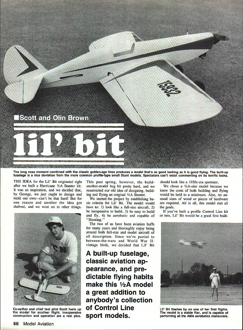
The long-nose moment combined with the classic golden-age lines produces a model that's as good looking as it is good flying. The built-up fuselage is a nice deviation from the more common profile-type small stunt models. Spectators can't resist commenting on its terrific looks.
THE IDEA
Lil' Bit originated right after we built a Hurricane 1/2A Stunter kit. Inspiration struck, and we decided we ought to design and build our own. For one reason or another the idea got shelved and we went on to other things. This past spring the build-another-model bug bit again, and we resurrected the idea of designing, building and flying an original 1/2A stunter.
We started the project by establishing basic criteria for Lil' Bit. The model would have to:
- Look like a full-size aircraft
- Be inexpensive to build
- Be easy to build and fly
- Be aerobatic and capable of stunting
We're partial to between-the-wars and World War II vintage birds, so we decided Lil' Bit should look like a 1930s-era sportster. We chose a 1/2A-size model to keep building and flying costs to a minimum and to avoid unusual wood sizes or hardware. A built-up fuselage, classic aviation appearance, and predictable flying habits make this 1/2A model a great addition to any control-line sport collection. If you've built a profile control-line kit, Lil' Bit would be a good first built-up plane.
Construction
First, study the plans and read the text carefully to get an idea of the work sequence and materials you'll use. We tackle the wing first, since it's the part most folks dread. The wing is built directly over the plans on a flat building board (2 x 4 ft.) soft enough to accept pins, such as Celotex. Use wax paper or clear plastic wrap over the plan so the finished wing won't be glued to the paper.
We used aliphatic-resin glue throughout the model except for two applications—the landing gear and tail-skid installations. It's safe, nontoxic, cleans up with water, dries quickly, is inexpensive, and is very strong (Elmer's Carpenter's Wood Glue, Franklin's Tite Bond, Sig Bond, etc.). Use a thin coating on mating surfaces and hold/clamp/pin parts while glue dries.
Another useful product is ZAR Latex Wood Patch (United Gilsonite Laboratories). It's an excellent wood filler that spreads well, dries quickly, sands smooth, and takes dope.
Wing
Fashion a jig directly over the plans to ensure a strong, straight structure. Trace the wing-spar jig piece from the plan onto paper, glue it to a rectangular piece of 1/16-in. sheet balsa slightly larger than the pattern, and cut out five more identical rectangles. Tack-glue the six pieces into a stack, let the glue dry, then cut all six jig pieces at once using the paper pattern on top as a guide. Split the stack apart carefully to get six identical jig pieces.
Make the main wing ribs using templates (thin sheet aluminum, brass, or plywood). Drill two 1/8-in. dia. holes—one at each end of the horizontal slot in the rib. Cut out 12 W-1 rectangular rib blanks slightly oversize, tack-glue them into a stack, and drill 1/8-in. holes through the stack using the rib templates for position. Bolt the templates to the stack, saw/carve/sand the stack to finished rib shape, remove bolts, split the ribs apart, and cut the center slots.
From 1/16-in. sheet cut four W-2 ribs, four wing tip ribs, and four wing tip gussets. From 3/32-in. sheet cut the wing tips and the two flap halves. Cut the flap joiner from 3/32 x 1/4-in. hardwood.
Pin the wing plan to the building board and cover it with wax paper. Pin the six wing-spar jig pieces upright on the dotted-line positions shown on the plan, with their square spar slots at the top. Use two pins on each side of each jig piece to hold them securely.
Cut two 1/16 x 3/4-in. trailing edge (TE) strips, two 1/8-in. sq. spars, and a 1/4-in.-sq. leading edge (LE) to length per the plan. Pin a TE strip over the TE on the plan and lay one 1/4-in.-sq. spar into the jig slots, aligning it with the plan.
Glue the main wing ribs (W-1 outboard, W-2 center) into place. Apply a little glue to the rear edge of each rib where it contacts the TE and into the square spar slot, then press the rib into place. Check alignment with a small square or drafting triangle to ensure ribs are vertical.
Assemble the flaps: inset the joiner strip into the leading edges of the flap halves, pin the flap halves to the plan, and glue the joiner strip. Pin or weight the assembly flat while it dries.
Install the control system in the wing. The total pull of a flying control-line model is borne by the control system—handle, flying wires, lead-out lines, bellcrank and mounting. Rig the system securely; a failure almost always results in a crash. Check flying wires, lead-outs, control horn and pushrod connections before every flight.
Attach lead-out lines to the bellcrank or flying-wire clips to the outboard ends of the lead-outs. Cut a 1 x 3/8-in. rectangle from 1/8-in. plywood for the bellcrank mounting platform. Drill the bellcrank mounting hole per plan, glue the mount in place in the W-2 and on top of the lower spar. Thread the three ends of the lead-out lines through the slots in the ribs of the left wing, position and install the bellcrank, then glue the upper spar in place, pinning it to the ribs.
Bevel the mating surfaces of both TE strips slightly to give a flat gluing surface about 1/16-in. wide. Pin and glue the upper TE strip to the ribs and to the lower TE strip at their rear edges. After the glue sets, remove pins and lift the wing off the jig.
Install wing tips with the wing standing on end. Glue tips to the outermost ribs and add tip gussets. Cut two 1/8-in. brass tubing lead-out guides to length, slip them over the outboard ends of the lead-out lines, and glue them to the top of the left wing at the plan locations—take care not to glue the lead-outs to the guides. These locations produce enough flying-line sweepback to keep Lil' Bit tight on the lines. Install flying-wire clips to the outboard ends of the lead-outs using the AMA rule-book method. Make the two lead-out lines as nearly the same total length as possible.
Glue the tip ribs onto the top and bottom sheeting of the wing tips. The top tip rib on the left wing needs notches for the lead-out guides. Cover the tip and bottom of the wing center section with soft 1/16-in. sheet balsa with the grain running spanwise. Cut out the pushrod clearance opening in the top sheeting and finish with sandpaper.
Sand wing surfaces with 100-grit garnet paper on a long sanding block (we use a 30-in. straight 1 x 2-in. pine block with 100 and 200-grit paper adhered). Hold the sanding block spanwise and work in small strokes to achieve a smooth, continuously curving, symmetrical wing profile.
Fuselage
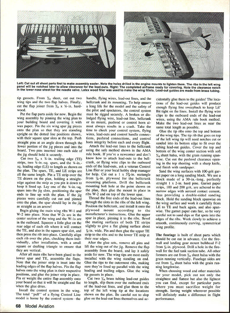
Cut the firewall and landing-gear mount bulkhead from 1/8-in. plywood. Drill a hole in the firewall for the fuel-tank suction tube. All other formers are cut from 3/32-in. sheet balsa with the grain running vertically. Fuselage sides are cut from 1/16-in. sheet balsa with the grain running lengthwise.
Choose the straightest, flattest, and lightest wood possible, except where strength requires heavier stock. Cut out openings for the wing, the pushrod exit slot in the right fuselage side, and the small pieces from each side just below the flap joiner strip—save these last two pieces to reinstall after flap installation.
Cut engine mounts from 1/4-in.-sq. hardwood (hard pine is acceptable). Drill lightening holes as shown on the plans and carve the notch in the left-hand mount for clearance of the upper fuel-tank vent tube. Glue engine mounts in place, aligning their top edges with the top edges of the fuselage sides. Note the two fuselage sides differ—follow the plans carefully. The mounts extend back to former F-3 to transfer engine vibration to the main wire airframe.
Lay the right fuselage side down on the board with the mount facing up, glue the firewall and formers F-3 and F-5 (but not F-1) to it, and check that formers are perpendicular to the side.
Fuel Tank Installation
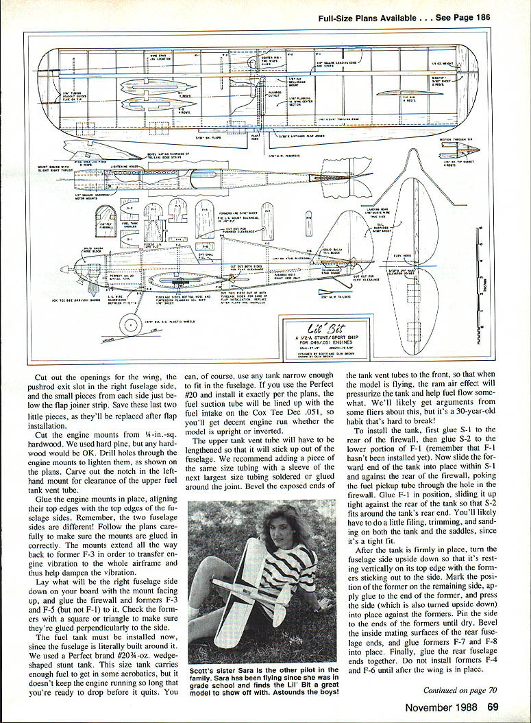
The fuel tank must be installed before closing the fuselage, since the fuselage is built around it. We used a Perfect #203 1-oz. wedge-shaped stunt tank. Install a tank narrow enough to fit the fuselage; if you use the Perfect #203 and position it per the plans, the suction tube will line up with the fuel intake on the Cox Tee Dee .051 for decent runs upright or inverted.
Lengthen the upper tank vent tube so it sticks up out of the fuselage. Add a piece of tubing with a sleeve of the next larger tubing soldered or glued around the joint. Bevel exposed ends of the tank vent tubes to the rear so rear airflow will help pressurize the tank.
Glue S-1 to the rear of the firewall, glue S-2 to the lower portion of F-1 (F-1 not installed yet), slide the tank forward into S-1 and against the firewall with the pickup tube through the firewall hole, then glue F-1 in position tight against the rear of the tank so S-2 fits around the tank's rear. Expect some fitting, filing and sanding for a tight fit.
After the tank is in place, turn the fuselage side upside down, mark positions and glue the other fuselage side to the formers, pin until dry. Bevel inside mating surfaces of the rear fuselage edges, glue formers F-7 and F-8 into place, and glue the rear fuselage ends together. Do not install formers F-4 and F-6 until after the wing is in place.
Power Plant
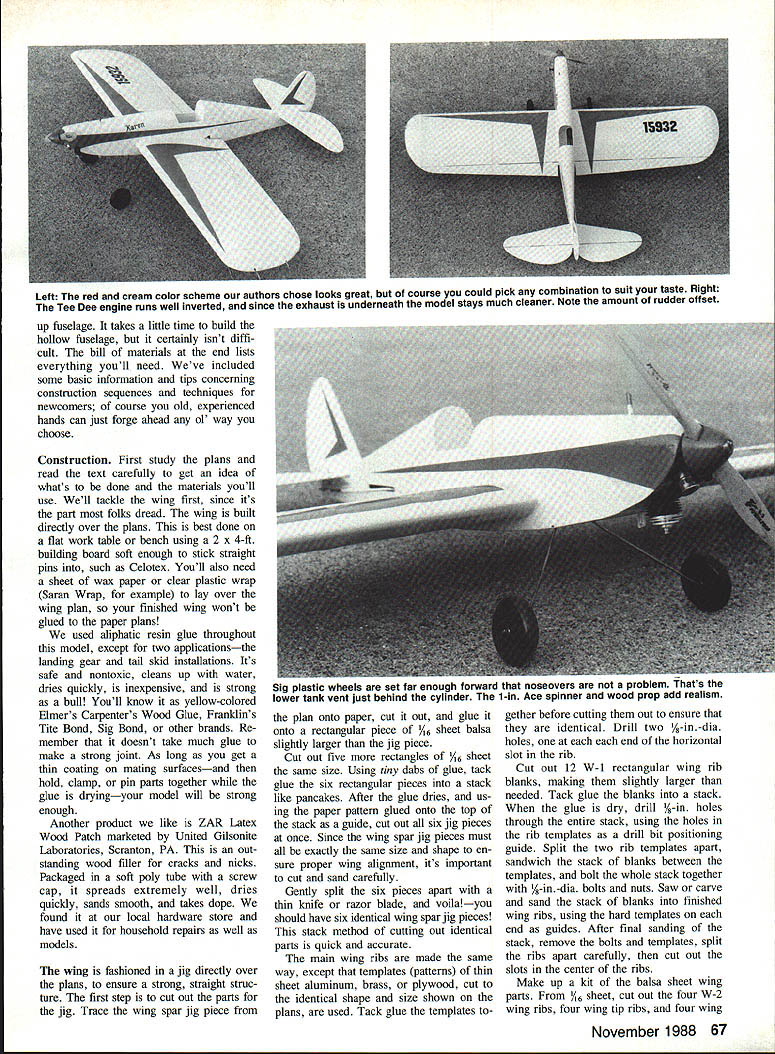
Cox .049 engines are powerful for their size. We had a Tee Dee .051 and designed the airframe around it and the tank. We inverted the engine for appearance; it runs fine inverted. The landing gear is far enough forward to keep the glow plug from scraping the ground in a nose-over.
With the fuselage upside down, position the engine on the mounts, turn it slightly toward the right side for a bit of out-thrust, and mark the four bolt-hole locations (remember the fuselage is upside down when marking). Drill holes for 2-56 x 3/8-in. bolts and bolt the engine in place with bolt heads up (so nuts and washers are below and won’t poke through the nose block). Install the fuel line and plug the tank vents with tape while sanding to keep out balsa dust. Wrap the engine with a cloth to keep it clean during construction.
Landing Gear
Bend the landing gear from 1/16-in. music wire following the full-size layout on the plan. Bend the gear legs forward as shown on the fuselage-side view. Install 1-1/8-in. lightweight Sig hollow-plastic wheels on axles and secure with setscrew wheel collars or epoxied washers on axle tips.
Lay the upper portion of the landing gear on former F-2, trace its outline, rout a groove in F-2 so the gear can be recessed, then epoxy the gear into the groove making sure the legs are angled upward so they'll be canted forward after installation. After epoxy sets, glue F-2 into the fuselage against the back of F-1 and clamp until dry.
Wing and Flap Installation
Slide the wing through the fuselage and center it so equal wing projects from each side. Square the wing to the fuselage—ensure the wing leading edge is perpendicular to the fuselage when viewed from above. When aligned, run a bead of glue inside and outside the fuselage at the wing-fuselage junction and where the bottoms of F-3 and F-5 contact the wing.
Cut 1/8-in. fabric flaps and hinge strips per the plan and glue them to the flap assembly. Glue the flap horn to the flap joiner strip. Slide the flap assembly into position against the wing TE (ensure the control horn sticks up) and glue the free hinge ends to the wing TE. Reinstall the two small cutout pieces into the fuselage sides and glue formers F-4 and F-6 into place.
Cut flap and elevator pushrods from 1/16-in. music wire. Slide wire keepers on the pushrods and bend right angles in the ends. Install pushrods in the bellcrank and flap horn and snap keepers into place. Wait until the elevator is installed before bending the elevator pushrod end.
Tail Surfaces
Cut tail surfaces from 3/32-in. sheet balsa. Glue the elevators to the joiner strip and pin/weight the assembly to dry. Glue the control horn to the joiner strip in the down-and-pointing position shown. Cut 1/2-in. fabric hinges and attach them to the stabilizer as with the flaps.
Position and glue the stabilizer in the fuselage. Alignment is critical: make sure the stabilizer is parallel to the wing when viewed from the front and rear, and that the elevator-stabilizer hinge line is parallel to the wing when viewed from above. A good check is to measure from the upper wing spar straight back to the outer stabilizer tip on each side to ensure symmetry.
Glue a short length of triangular stock under each side of the stabilizer where it adjoins the fuselage to reinforce the joint with minimal weight. Glue the vertical stabilizer in place, making sure it is absolutely vertical, and check with a square. Glue the rudder to the vertical stabilizer and rear fuselage, angling it slightly for a little right offset. Bend the tail skid from .032 music wire and epoxy it in place.
Cut nose and tail blocks from soft solid balsa, cut 1/32-in.-wide slots in the tail block for the vertical and horizontal stabilizers, hollow the underside of the nose block to clear the engine crankcase, then glue blocks in place. Cut and install a triangular piece of sheet balsa between the rear fuselage sides to serve as a platform for the stabilizer, then glue the stabilizer tight against the rear of F-8.
Fill cracks or gaps with wood filler, sand blocks to contour, and continue filling and sanding until smooth.
Sheet and Finish
Sheet the upper fuselage sections with soft 1/16-in. sheet balsa. Make stiff paper patterns for the upper forward fuselage and turtledeck, transfer to balsa, cut slightly oversize, soak the sheet with water until pliable, apply glue to the formers, wrap the sheet over the formers, and pin to hold while drying. Score the top surface lightly where the sheet wraps over F-8 to prevent splitting.
Sheet the bottom of the fuselage with sections of 1/8-in. balsa with the grain running crosswise.
Any covering system is satisfactory, including iron-on coverings; we prefer the silkspan-and-dope route. Brush a coat of fuel-proof clear dope on the wing leading and trailing edges and center planking, sand lightly with 400-grit wet-or-dry paper, then cover the wing with lightweight silkspan with the grain spanwise. Dope the silkspan only to the leading and trailing edges and wing-tip edges—do not dope the silkspan to the ribs or the covering won't be able to shrink properly and you'll get sagging.
After dope dries, shrink the silkspan by spraying lightly with water and letting it dry thoroughly. Dry-sand the airframe with 400-grit wet-or-dry paper and apply three coats of Sig sanding sealer, sanding lightly between coats. We chose Sig Diana Cream overall with Stearman Red trim and black numerals. A couple of finish coats of clear dope will add shine. Apply your AMA license number to the upper right wing surface.
Flying
We flew Lil' Bit on Sullivan-brand .012-in. x 35-ft. braided lines after carefully checking all line, pushrod, and horn connections. We also filter Cox fuel through a paper coffee filter to remove debris—small engines are sensitive to dirty fuel.
On the first takeoff Scott chose a full-up-elevator catapult shot. With the Tee Dee wound up, swinging a Cox 6 x 4 plastic prop and an ABC RC 1-in. spinner, Lil' Bit jumped off the ground and climbed rapidly. The initial takeoff was a wingover with some dancing in the circle until order was restored. Lil' Bit flies exceptionally well and is capable of flying the whole pattern. We suggest placing pushrods in the least sensitive control-horn positions until you get the feel of the machine.
Always check the control system, flying wires, lead-outs and handle connections before each flight, and fly safely away from power lines.
Bill of Materials
Sheet Balsa
- 1/16 x 4 x 36 in., soft — fuselage top & bottom coverings, ribs
- 1/16 x 3 x 36 in., soft — fuselage sides, ribs, jig pieces
- 1/8 x 3 x 36 in., soft — formers, flaps, tips, tail surfaces
Other Balsa
- 3/16 x 3 x 36 in., med. — wing LE, spars, stabilizer braces
- 2 — 1/16 x 3/16 x 36 in., soft — wing TEs
- 1 — 1/4 x 1/4 x 4-1/2 in., soft block — nose & tail blocks
Other Wood
- 1 — 3/16 x 1/4 x 19 in. hardwood strip — flap & elevator joiners
- 1/16-in. plywood, approx. 1-1/4 x 7-1/2 in. — firewall, landing gear bulkhead, bellcrank mount
- 1/4 x 1/4 x 13 in. hardwood — motor mounts
Hardware & Materials
- Plans
- Building board
- Straight pins
- Wax paper
- 1 — Cox Tee Dee .049 or .051 engine
- 1 — propeller, 6 x 4, Cox plastic or Top Flite, Zinger wood
- 1 — 1-in. plastic spinner, Ace R/C, Inc.
- 1 — 4-oz. wedge fuel tank, Perfect #20 (or Perfect #203 1-oz. wedge tank as used)
- 1 — 1/8-in. brass tubing — tank vent extension, lead-out guides
- 2 ft. 3/32-in. small plastic flexible fuel line
- 1/8 x 28-in. music wire — pushrods, landing gear
- 1/32 x 4-in. music wire — tail skid
- 1/2-in. bellcrank with mounting hardware, Perfect or comparable
- 36-in. length braided lead-out line, Perfect or comparable
- 1 pair — flying wire clips, Perfect, Du-Bro, or comparable
- 1 pair — 1-1/4-in. dia. plastic wheels, Sig or comparable
- 1 pair — 3/16-in. wheel collars, Perfect, Du-Bro, or comparable
- 4 — 2-56 x 3/8-in. engine mounting bolts with locknuts
- 2 — small control horns, Perfect or comparable — flaps, elevator
- 4 — wire pushrod keepers for 5/32-in. dia. music wire
- 48 in. x 3/4 in. or similar fabric control-surface hinges
- Aliphatic resin glue, Franklin Tite Bond or comparable
- Five-minute epoxy glue, Duro or comparable
- Garnet paper, 100- and 200-grit, Norton or comparable
- Fuel-proof dope — 400-grit, 3M or comparable
- 1 sheet — lightweight silkspan
- Fuel-proof dope — Sig Clear, sanding sealer, Diana Cream and Stearman Red or comparable
- 1 in. numerals for AMA license number
- 1 set — .012-in. x 35-ft. braided steel flying wire, Sullivan or comparable
- 1 — 1/4 A control handle, Sullivan or comparable
- Cox Super Power Glow Fuel
The above parts and materials should be available at your local hobby shop. Control line supplies are still obtainable—don't accept "we can't get that anymore" without checking other sources.
Transcribed from original scans by AI. Minor OCR errors may remain.

