
Lil' Chugger
National Free Flight Society's Small Power Model of the Year
Robert Dunham II
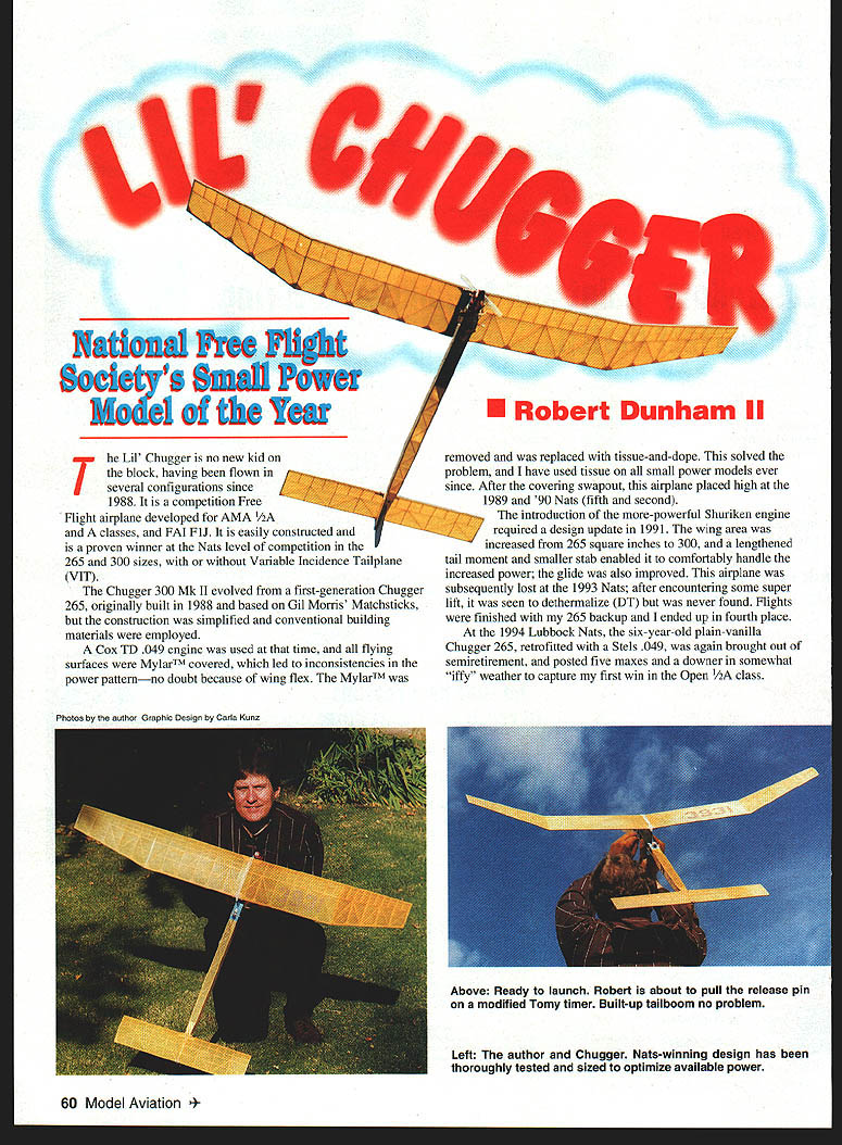
The Lil' Chugger is no new kid on the block, having been flown in several configurations since 1988. It is a competition Free Flight airplane developed for AMA 1/2A and A classes, and FAI F1J. It is easily constructed and is a proven winner at the Nats level of competition in the 265 and 300 sizes, with or without Variable Incidence Tailplane (VIT).
The Chugger 300 Mk II evolved from a first-generation Chugger 265, originally built in 1988 and based on Gil Morris' Matchsticks, but the construction was simplified and conventional building materials were employed.
A Cox TD .049 engine was used at that time, and all flying surfaces were Mylar™ covered, which led to inconsistencies in the power pattern—no doubt because of wing flex. The Mylar was removed and replaced with tissue-and-dope. This solved the problem, and I have used tissue on all small power models ever since. After the covering swapout, this airplane placed high at the 1989 and 1990 Nats (fifth and second).
The introduction of the more-powerful Shuriken engine required a design update in 1991. The wing area was increased from 265 square inches to 300, and a lengthened tail moment and smaller stab enabled it to comfortably handle the increased power; the glide was also improved. This airplane was subsequently lost at the 1993 Nats after encountering some super lift; it was seen to dethermalize (DT) but was never found. Flights were finished with my 265 backup and I ended up in fourth place.
At the 1994 Lubbock Nats, the six-year-old plain-vanilla Chugger 265, retrofitted with a Stels .049, was again brought out of semiretirement and posted five maxes and a downer in somewhat "iffy" weather to capture my first win in the Open 1/2A class.
CONSTRUCTION
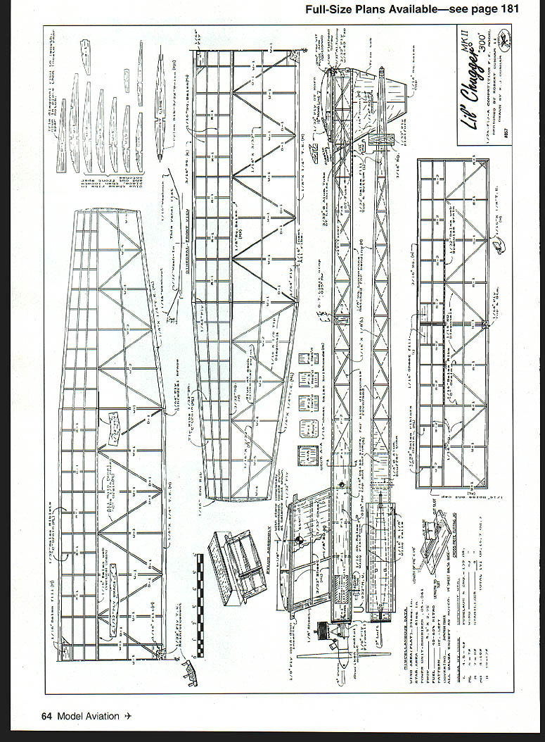
Spend a couple evenings studying the plans before you scratch-build the project. Although it is not difficult, you should have some previous knowledge of working balsa structures and should have built several similarly constructed models. If you have a good Cox TD/AME .049 you wish to use, take the 300 plan to a copy shop and have a print made using a 95% reduction factor — cost will be minimal. The result will be a 265-square-inch flat-wing plan; everything else will be in proper proportion. Wood sizes remain the same. The finished weight combination should exceed 6.25 ounces.
Use Duco cement as the primary glue for balsa construction because of its lightness, repairability, and because it sands well. Cyanoacrylate (CyA) glues and epoxies have applications in heavily fuel-wetted areas but should be used sparingly on primary structure. For quick-fix field repairs, CyA can be your best friend.
Fuselage
- If there are any skeptics about the merits of stick-and-tissue tailbooms, my four Chuggers have logged several hundred flights and none has had a boom broken for any reason. Small, lightly loaded power models descend slowly in the DT mode and land without much fuss. The fabricated wooden structure seems forgiving and flexes without breaking.
- The main 1/8" square longerons should be matched as closely as possible for grain, stiffness, and hardness. If you use prestripped stock this can be difficult; consider building, borrowing, or buying a balsa stripper and cut your own strips from sheet stock. Produce four good square-sided strips and tag one end so you can keep track of how they came off the sheet. Pin to the plan with the heavy end at the nose.
- Install the 1/16" sheet side panels and position the vertical uprights as shown on the plan. Add the diagonals; a simple cutting jig can be helpful to produce them en masse with minimal effort.
- Repeat for the companion side, which I construct directly on top of the one just completed. Remember, the diagonals on this side run to opposite corners, which makes the structure fully geodetic when finished.
- Remove the sides from the plan and separate them; lightly block-sand front and back to remove glue bumps and other irregularities.
- Carefully prepare the 1/16" bulkheads from six-pound balsa, making sure they are cut accurately with square corners. Lay the right-side structure flat on the building board and glue in the bulkheads at the appropriate positions, keeping them vertical until set. Glue the left side to the vertical bulkheads, two positions at a time, beginning at F-1 and working back to F-3, keeping everything aligned and true.
- Lift the basic fuselage frame from the building board, then drop in and glue the forward fuselage bottom panels (grain the long way) and top panel (cross-grain). Install all cross-members and diagonals from F-3 forward, and let everything set for at least an hour.
- Bring the fuselage sides together at the rear. Before gluing, cut former F-4 to width to retain the curvature you have chosen. When satisfied with the symmetrical appearance, glue everything together and install the top and bottom braces, followed by the diagonals.
- The front firewall is 1/8" plywood; the engine mounting method will depend on the power plant selected. You can probably purchase a machined radial-mount adapter ring, which replaces the engine backplate and simplifies mounting. Blind mounting nuts are installed on the back side of the plywood to accept the ring, and the firewall is slow-cure-epoxied in place on the fuselage with thrust offsets as shown on the plan.
Timer and cutoff
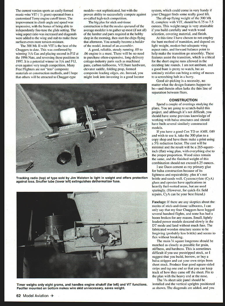
- I have used modified Tomy timers for the engine cutoff and VIT activation on small power models for many years. I find them reliable, steady-running, and minimally affected by engine vibration; they also tolerate a reasonable amount of disc loading.
- Most timer malfunctions are centered around pilot error — not activating the start button, incorrect disc positioning, wrong line hookups, etc. They happen to everyone.
- The manufacturer continually introduces new figures with different articulations and shaft takeoffs. I never know until disassembly whether the toy will be suited to my application, but I was fortunate to find a Tomy motorboat with the attributes required and purchased a dozen of them.
- I will not elaborate on modification procedures here; several good articles have been published in U.S. and British magazines. Note the Tomy's eight-gram finished weight, low cost, and entertaining motion prior to modification.
- The crossover wire system makes it unnecessary to slow down the pawl, reducing the chance of stalling the action. If this happens, the end result is a total disaster and you will need to bring in another load of balsa.
- If you don't want to try your luck with a Tomy, purchase a Texas Timer 1/2A Mini or Seelig four-function 1/2A timer. Both are dependable and require no modification, but weigh 16–20 grams. Line hookups will require some improvisation depending on whether you run the lines internally or externally, and whether you choose VIT or locked-up. Remember the 9–12 gram weight penalty rides along on every flight.
Pylon
- Build the wing pylon in halves. Prepare the 1/8" x 1/2" leading and trailing edges with the 1/8" plywood hold-down inserts epoxied in place.
- Cut three pylon ribs from 3/32" balsa sheet; two are cut in half lengthwise and match-marked.
- Pin the LE and TE pieces on the plan and glue in only the bottom and middle half-ribs. Remove from the plan and attach the companion half-ribs and the full top rib. Fit and glue the 1/8" square vertical stiffener. Add 1/32" sheet sides and trim edges.
- Piece the 1/16" sheet wing platform together and cut to length and width. Add the 1/16" x 1/8" hard edge runners, then glue the completed platform to the pylon with careful alignment. Set aside until final assembly; when the airplane is completely assembled, locate the pylon with the CG at 66% chord.
Wing
- The wing is constructed in separate panels. Choose wood near the density and grain indicated; an accurate gram scale helps.
- Make a 1/16" plywood cutting template of center panel rib W-1. Push straight pins through the template at two positions (just barely protruding) and CyA it in place. The pins keep the template steady while slicing ribs from light 1/16" C-grain balsa sheet. Locate the spar notches during this operation.
- Choose the trailing edge from warp-free medium-weight 1/8" x 1/4" strip stock. Locate and cut the rib inset notches (about 1/4" deep) with a Dremel scroll saw. These inserts greatly strengthen the rib attachment point and should be a tight fit. The TE has a very slight taper to conform with the top camber slope; a sanding block or mini razor-plane will do this job if you are careful.
- Pin the LE, TE, and 1/8" square bottom spar on the plan and lay in the full straight ribs. Install the 1/16" vertical shear webs flush with the back edge of the bottom spar. Install the half-ribs, followed by the 1/8" square top spar. Cut and install diagonal ribs from C-grain sheet. Omit the rear spar notches for now; they can be located more accurately after the panels are joined.
- Tip panels use 1/16" x 1/8" diagonals between full straight ribs. At each crossover point the diagonals should be glued to the rear spar. If the crossover doesn't touch the spar, bridge the gap with short scrap balsa pieces. These glue points add torsional stiffness and help prevent high-speed flutter and twisting.
- Prepare completed panels for polyhedral by carefully trimming and sanding LE, TE, and main spars so abutments are tight. Use epoxy and overlapping 1/32" plywood braces. Embed small 1/8" plywood keepers where the TE has limited gluing area. When carving the LE to shape, introduce a small amount (3/32") of entry camber to the bottom side.
- Add TE wing rubber plywood reinforcement, LE balsa fill, and slanted 3/32" tip ribs. Sand the whole structure smooth and prepare for covering.
Stabilizer
- Construction is similar to the wing, but the trailing edge is an L-shaped cross-section using 1/16" x 1/8" medium balsa. Use light wood throughout; target finished weight is 9–11 grams.
- Construct and install the stab mount. A slight amount of left-turn tilt (3/16") should be visible, which translates to the left tip being high when viewed from the rear.
Covering and finish
- Japanese tissue is the recommended covering material, principally because of its light weight and tautness. Give all structures and edges that contact the covering a coat of unthinned butyrate dope; lightly sand with 200-grit paper to remove fuzz and raised grain. Apply tissue with the same dope and spray with water to tighten.
- Apply two coats of thinned clear dope to the flying surfaces and the boom portion of the fuselage. Double-cover the bottom side of the first three inboard bays of the wing with tissue, water-shrink, and dope. Spray a colored dope or paint to the front of the fuselage starting just behind the pylon to protect against fuel spray and handling.
- Introduce a small amount (3/32" or less) of washout (trailing edge high, viewed from the rear) into the tip panels by holding them in position until the dope has dried. Over-wrapping is generally needed since the structure tends to return to its original shape; aim to retain about 1/16" washout. Use the same method to apply about 1/8" washin to the right main wing panel.
- Check these intentional warps periodically, especially in damp conditions and before competition flights. They are best induced during the covering operation rather than built into the open-structured surfaces.
Preflight and trimming
- Complete all detail work and prove out flight systems before going to the field. The wing is keyed with short lengths of 1/8" square balsa, resulting in a slide fit on the wing platform.
- Locate the center of gravity (CG) within the range of 62–66% of the wing chord; the fuselage ballast will make corrections. Do not let the CG be rearward of 66%, or flight adjustments could become complicated.
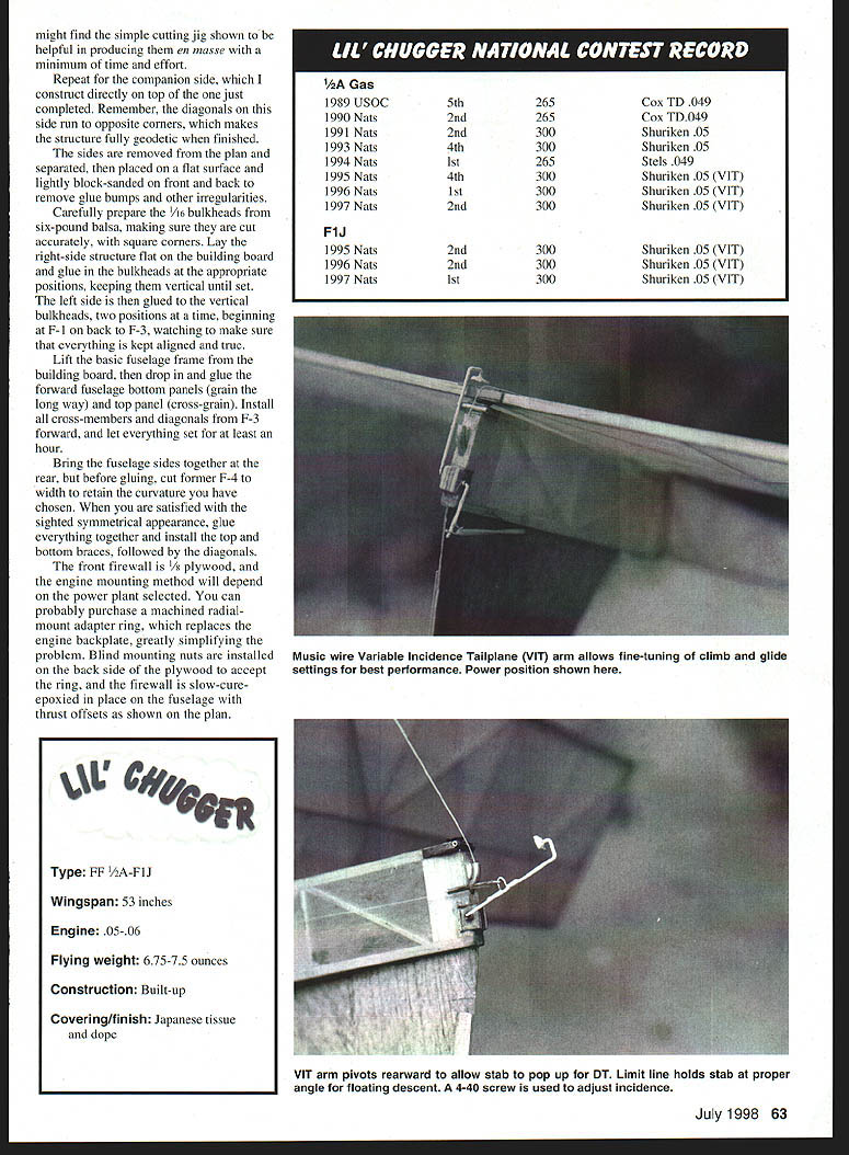
- Ensure the VIT/engine cutoff timer disc is not overloaded so that it will run steadily, but it must withstand sufficient rubber band tension to keep the stab firmly seated in the power mode.
- Ensure the fuel pinchoff mechanism (a Reid Simpson gadget) is close to the engine needle valve, closes securely, and is foolproof. Check this with the engine running and observe the rotational speed of the timer disc; mark the three-second location for initial test flights.
- Maiden-test hop procedure:
- Test-glide over high grass with the stab in the glide position and the prop removed. The optimum glide is a slight left bank with no stall tendency.
- Correct any stall or dive by adjusting the wire VIT arm with needle-nose pliers or by adding 1/64" plywood shims to the stab top or bottom rubber plates.
- For initial power setting, lower the stab TE about 1.5 turns of the 4-40 adjusting screw. Never fly without a fuse—install a short fuse with the end charred for easy lighting. Set the engine timer for no more than three seconds.
- Start and needle the engine to nearly full power using mild fuel (30% nitro). Light the fuse and gently launch the Chugger straight up, keeping the wings level. It should accelerate rapidly in a nearly vertical right spiral and be about 200 feet high when the engine cuts. Observe the glide before DT and correct any dive or stall by adjusting the wire VIT arm.
- If the Chugger heads for a vertical loop under power, it is overelevated—lower the stab adjustment screw 1/4–1/2 turn depending on severity. If the power pattern is flat (arcs over toward the ground), it is underelevated—raise the screw 1/4–1/2 turn.
- Adjust the glide circle with stab tilt to approximately 150 feet in diameter. Adjust the power turn with small rudder-tab changes; these changes have magnified effect during high-speed climb. If engine thrust offsets are built in correctly, no further adjustments should be required.
- On long engine runs you may observe a gentle left roll combined with the right turn. This is acceptable unless excessive. The right-wing wash-in becomes effective at high speed, helping lift against the right-turn induced by prop wash impinging on the pylon and underslung rudder while keeping the nose up during the climb.
- As climb and glide patterns are optimized, gradually increase fuel nitro and engine run up to seven seconds. Longer gliding flights can be observed before DT. This may take a dozen flights and more than one test session.
Flyoff Tactics
- The Chugger should be capable of consistently making AMA Cat. III seven-second engine runs and two-minute max flights. It is more difficult to be consistently successful with the four-second engine run, 2-1/2-minute max. When you reach this plateau, observations and careful attention to detail are required before each official flight.
- Perform a ground (and possibly air) check of the engine run; second attempts are not allowed. Back off the engine timer slightly to allow for sound travel and timekeeper reaction delays.
- Time management is important late in the day when only a few fliers remain. Few airplanes with short engine runs are being flown late, so you may need other means (bubbles, streamers, or thermistors) to monitor air quality.
- Flyoffs commonly occur in the waning hours of the meet when the air is cooling. If you are more than one flight behind and less than an hour remains, consider assembling a backup model so flights can be put up in rapid succession. Preparing a second airplane can sometimes unsettle opponents.
- Arrange chasing help so you can remain on the flightline and get airborne again quickly.
- In F1J, rounds for the first five flights are followed by progressively longer maxes for the flyoff. Under some conditions, long flights introduce the timer's eyesight into the equation; always supply the timer with a good pair of binoculars and ask him to focus in well in advance of the airplane disappearing. Have him spot the airplane down and mark the line with a terrain feature.
LIL' CHUGGER NATIONAL CONTEST RECORD
1/2A Gas
- 1989 USOC — 5th — 265 — Cox TD .049
- 1990 Nats — 2nd — 265 — Cox TD .049
- 1991 Nats — 2nd — 300 — Shuriken .05
- 1993 Nats — 4th — 300 — Shuriken .05
- 1994 Nats — 1st — 265 — Stels .049
- 1995 Nats — 4th — 300 — Shuriken .05 (VIT)
- 1996 Nats — 1st — 300 — Shuriken .05 (VIT)
- 1997 Nats — 2nd — 300 — Shuriken .05 (VIT)
F1J
- 1995 Nats — 2nd — 300 — Shuriken .05 (VIT)
- 1996 Nats — 2nd — 300 — Shuriken .05 (VIT)
- 1997 Nats — 1st — 300 — Shuriken .05 (VIT)
LIL' CHUGGER (SPECIFICATIONS)
- Type: FF 1/2A–F1J
- Wingspan: 53 inches
- Engine: .05–.06
- Flying weight: 6.75–7.5 ounces
- Construction: Built-up
- Covering/finish: Japanese tissue and dope
I hope that you build the Lil' Chugger, and that our paths will cross at some future competition. If so, please introduce yourself and relate your experiences with this design. If you have questions or want to confer on a building question, please contact me:
Robert Dunham II Box 904006 Tulsa, OK 74105
Transcribed from original scans by AI. Minor OCR errors may remain.

