
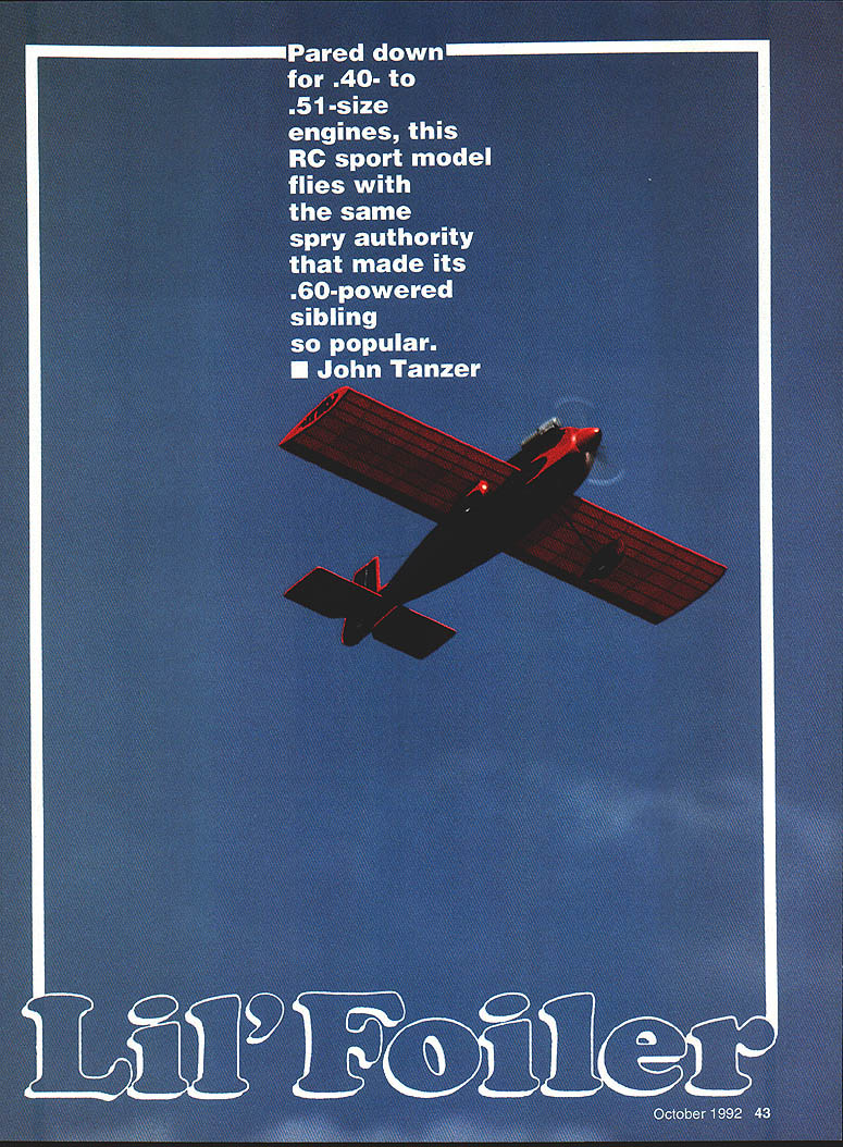
Lil' Foiler
John Tanzer
Pared down for .40- to .51-size engines, this RC sport model flies with the same spry authority that made its .60-powered sibling so popular.
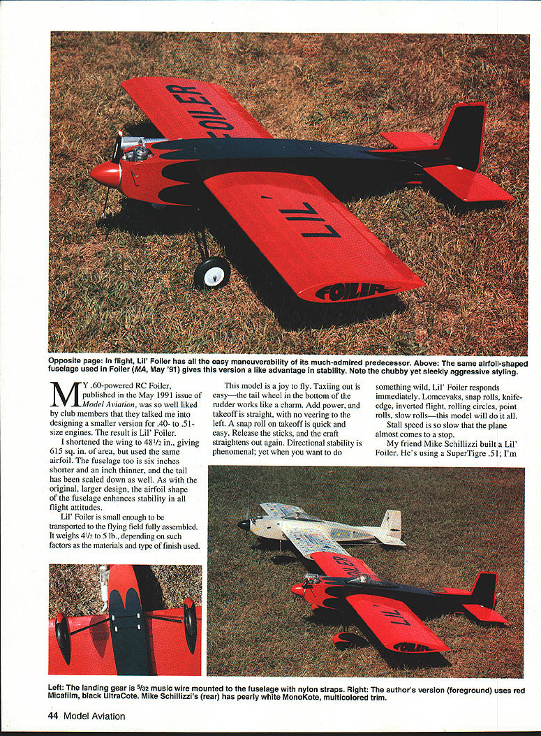
My .60-powered RC Foiler (published in the May 1991 issue of Model Aviation) was so well liked by club members that they talked me into designing a smaller version for .40- to .51-size engines. The result is Lil' Foiler.
I shortened the wing to 48-1/2 in., giving 615 sq. in. of area, but used the same airfoil. The fuselage is six inches shorter and an inch thinner, and the tail has been scaled down as well. As with the original larger design, the fuselage airfoil shape enhances stability in all flight attitudes.
Lil' Foiler is small enough to be transported to the flying field fully assembled. It weighs 4-1/2 to 5 lb., depending on materials and finish.
This model is a joy to fly. Taxiing out is easy—the tail wheel in the bottom of the rudder works like a charm. Add power, and takeoff is straight, with no veering. A snap roll on takeoff is quick and easy; release the sticks and the craft straightens out again. Directional stability is phenomenal, yet when you want to do something wild Lil' Foiler responds immediately: Lomcevaks, snap rolls, knife-edge, inverted flight, rolling circles, point rolls, slow rolls—this model will do it all. Stall speed is so slow the plane almost comes to a stop.
My friend Mike Schillizzi built a Lil' Foiler using a SuperTigre .51; I'm using a Royal .45 ABC. Both models are quite fast—too fast at full throttle; reduce throttle for calmer flying. The plane can be slowed for spot landings more easily using an 11x6 or 11x5 APC propeller.
The basic structural design of the original Foiler is unchanged, though I added an optional canopy and wheelpants for appearance. Don't be put off by the wing subspars—this construction method is easier, faster, and lighter than a sheeted D-tube with cap strips, and the wing will be warp-free once covered.
Specifications
- Type: Sport
- Wingspan: 48-1/2 in.
- Wing area: 615 sq. in.
- Recommended engine: .40–.51 cu. in. two-stroke
- Recommended RC channels: Four
- Expected flying weight: 4-1/2 to 5 lb.
- Construction: Built-up
- Covering/finish: MonoKote or Micafilm on wings and stabilizer; UltraCote on fuselage and rudder
Construction
Wing
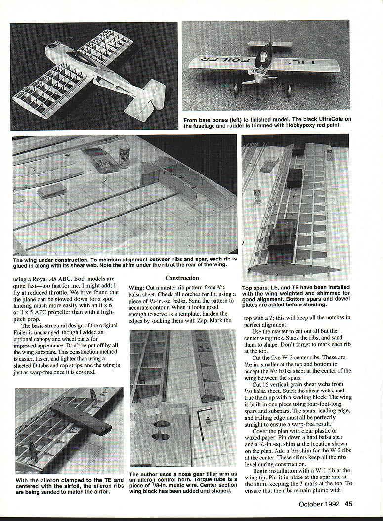
- Cut a master rib pattern from 3/32-in. balsa sheet. Check notch fit using a piece of 1/4-in.-sq. balsa. Sand the pattern to an accurate contour, harden the edges with Zap (CA glue), and mark the top with a "T" to keep notches aligned.
- Use the master to cut out all ribs except the center wing ribs. Stack ribs and sand to shape; mark the top of each rib.
- Cut five W-2 center ribs from 3/32-in. balsa. The top and bottom of these center ribs are reduced to accept 3/32-in. balsa sheet that will be fitted between the spars at the center of the wing.
- Cut 16 vertical-grain shear webs from 3/32-in. balsa sheet. Stack and true them up with a sanding block.
- The wing is built as one piece using four-foot-long spars and subspars. Ensure spars, subspars, leading edge (LE), and trailing edge (TE) are perfectly straight for a warp-free wing.
- Cover the plan with clear plastic or waxed paper. Pin down a hard balsa spar and a 1/4-in.-sq. shim at the location shown on the plan. Add 1/32-in. shims at the W-2 ribs to keep ribs level during construction.
- Begin installation with a W-1 rib at the wing tip. Pin it in place at the spar and the shim, keeping the "T" mark on top. Work toward the center, gluing each rib to its shear web with Zap as you go. Leave the center rib out. Repeat for the second panel, again leaving the center rib out.
- If ribs don't align exactly with the plan, don't worry—some shear webs may be slightly longer or shorter. If the center bays are narrower than shown, cut down two webs to fit the center rib.
- Add 1/4-in.-sq. hard balsa subspars. Cut a 1/4 x 1/8-in. trailing edge oversize so it extends equally above and below the rear ribs; it will be sanded flush later. Zap the trailing edge in place where necessary and true the panel.
- Glue in the 3/8-in.-sq. balsa leading edge. Remove the wing from the plan, turn it over, pin and shim it, and glue in the remaining bottom spars. Install 1/8-in. plywood dowel plates at the leading edge.
Center section and sheeting
- Cut 3/32-in. balsa sheeting to width for the center section. Hold sheeting against a spar and mark each end of the adjacent spar with a No. 11 X-Acto blade, then cut to final width using a metal straightedge. Light sanding may be required to fit.
- Remove the center shim, pin or weight the wing on one of the 1/4-in. spars, and finish sheeting the center.
- Cut two wing tips from 1/4-in. balsa sheet and glue them in place. Sand the trailing edge flush with the ribs and plane/sand the leading edge to a round radius—sharp leading edges cause abrupt stalls and pitch sensitivity.
Ailerons and torque rods
- Make two aileron torque rods from 1/8-in. music wire. Use plastic, aluminum, or brass tubing as bearings and glue the bearings to the trailing edge.
- Glue a balsa block to the trailing edge with a groove for the aileron bushings and holes for the aileron horns. I use two nose-gear steering arms for aileron horns because they can be removed easily while the wing is being covered.
- Clamp the aileron at the trailing edge to center it in the airfoil. Cut 3/32-in. balsa rib tails and glue them top and bottom at the proper locations. Use 80-grit paper for rough sanding and a sanding block to fair the aileron ribs into the aileron.
- Plane and sand the ailerons. Cut them from 3/32-in. balsa sheet and glue 3/32 x 1/2-in. balsa sticks to the front of the ailerons top and bottom.
- Install balsa blocks to secure the torque rods. Drill a 1/8-in. hole in the end blocks for the torque rod. Use Sig Easy Hinges for the ailerons; cut slots in the wing sheeting for the hinges. Do not glue the hinges yet. Install the aileron servo and check operation before covering. After covering, use a drop of Zap to prevent aileron horns from slipping on the torque rods.
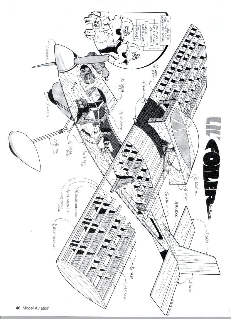
Fuselage
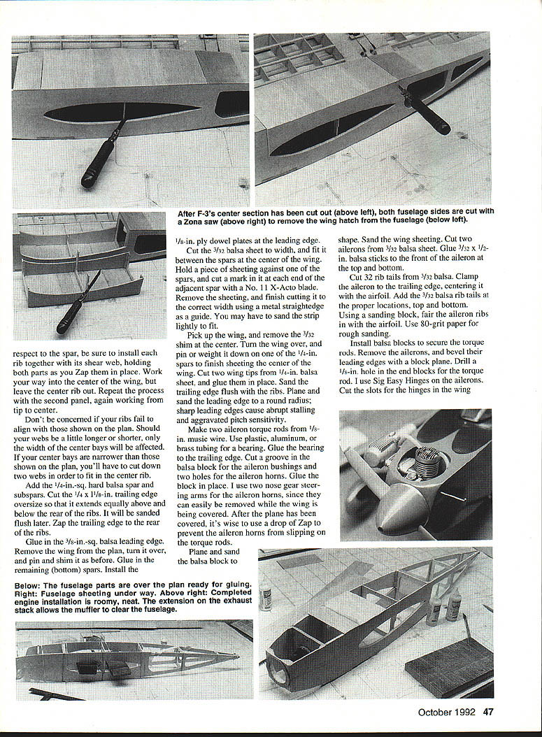
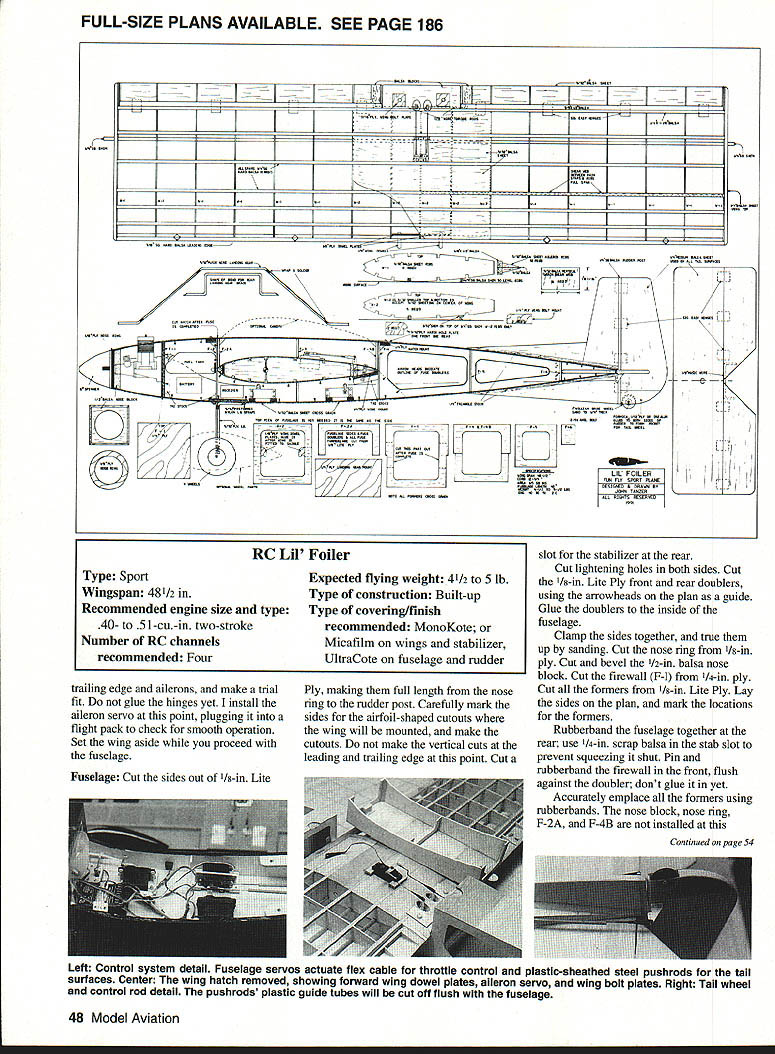
- Cut the fuselage sides from 1/8-in. Lite Ply, full length from nose ring to rudder post. Mark and cut airfoil-shaped wing saddle cutouts; do not make the vertical cuts at the LE and TE yet. Cut a slot for the stabilizer at the rear. Cut lightening holes in both sides.
- Cut 1/8-in. Lite Ply front and rear doublers and glue them to the inside of the fuselage sides per the plan.
- Clamp the sides together, true them up by sanding, and prepare the nose ring from 1/8-in. ply. Cut and bevel the 1/2-in. balsa nose block. Cut firewall (F-1) from 1/4-in. ply and all formers from 1/8-in. Lite Ply. Lay the sides on the plan and mark former locations.
- Rubberband the fuselage together at the rear and use scrap balsa in the stab slot to prevent squeezing it shut. Pin and rubberband the firewall in front (flush against the doubler) but do not glue it yet. Emplace all formers with rubberbands—a number of formers (nose block, nose ring, F-2A, F-4B) are not installed at this stage.
- Place the rubberbanded fuselage on the plan side view and weight it down. When straight and aligned, Zap all the joints, pull the front together, glue in the nose block, and add the nose ring.
- Glue in F-2A and F-4B hatch formers, keeping them separated from F-2 and F-4 with spacer strips cut from a plastic jug. Extend spacers above the formers to separate them from the sheeting.
- Turn the fuselage over and glue in the 1/4-in. ply landing gear plate. Reinforce joints with triangular stock where indicated on the plan.
- Sheet the top and bottom of the fuselage with 3/32-in. cross-grained balsa, leaving the front open from a point 1 in. forward of F-2 for engine installation.
- Cut the center wing section from F-3, remove plastic spacers, and cut down both fuselage sides with a Zona saw to remove the hatch. Glue in the 1/4-in. ply wing bolt mounts.
- Fit the wing in the saddle and check alignment. Mark the leading edge for 1/4-in. wing dowels that will mate with F-2. Remove the wing, drill 1/4-in. holes in the leading edge, and glue in the dowels.
- Replace the wing and glue in the 1/8-in. ply dowel plates. Glue the 1/16-in. ply wing bolt plate to the top of the wing block at bolt location.
- Drill holes through wing and 1/4-in. ply wing bolt mounts using a #7 (13/64-in.) drill. Remove wing and tap ply mounts for 1/4-20 plastic bolts; harden threads with Zap. Redrill wing holes to 1/4 in.
- Glue 1/4-in. ply hatch screw blocks to the fuselage formers. Install the wing and bolt it down securely.
- Trial-fit the wing hatch, recessing it for the 3/32-in. ply hold-down plates and glue the plates in place. Use panhead screws to secure the hatch.
- With the top front fuselage still un-sheeted, install engine mount, engine, fuel tank, and throttle cable. Finish sheeting the fuselage, leaving an opening just large enough to remove the engine through the top. A muffler extension will likely be required to move the muffler outboard clear of the fuselage side.
- Fair the nose block into the spinner.
Landing gear
- Bend landing gear and doubler from 5/32-in. music wire using the plan as a guide. Mount to the fuselage with preformed 5/32-in. nylon landing gear straps.
- Wrap the gear pieces together with copper wire and solder them.
- I do not recommend substituting aluminum or fiberglass gear. Hard landings are common at fun flies; wire gear will bend rather than shear off and break the wing or tail, and can be bent back to fly again.
Tail surfaces
- Cut all tail parts from medium 1/4-in. balsa sheet.
- Join the elevators with 1/8-in. music wire glued in place. Bevel the front of the elevators and temporarily insert Sig Easy Hinges; do not glue hinges yet.
- Glue the stabilizer into the rear slot, making sure it is at 0° incidence with respect to the wing.
- Pin the rudder, fin, subfin, and 1/4-in. rudder post to the fuselage, check alignment, and glue in place.
- Glue 1/4-in. triangular balsa stock to both sides of the rudder, fin, and subfin where indicated on the plan.
- Cut a hole in the bottom of the rudder and glue Formica, 1/32-in. ply, or .032-in. aluminum to both sides to create a pocket for the 1-in. tail wheel. Sand the tail wheel down to 1/4-in. thickness and cut a brass tubing bushing slightly wider than the wheel hub. Use a 2-56 bolt as an axle.
- Cut slots for Sig Easy Hinges in the rudder and rudder post and check alignment by temporarily inserting the hinges. Do not glue them yet.
- All control surfaces will be mounted after covering; the rudder post will be cut for proper elevator travel.
- Mount fuselage servos on their sides under the wing. Use a flex cable for throttle control. Steel pushrods encased in plastic tubing operate the tail surfaces.
Control throws and balance
- Aileron travel: 5/8 in. up and down.
- Elevator travel: 3/4 in. up and down.
- Rudder: as much travel as possible.
- The center-of-gravity coincides with the main spar location. Both Mike's model and mine balance without added weight.
Finishing
- Mike covered his model with pearly white MonoKote and multicolored trim. I used red Micafilm on the wings and stabilizer and black UltraCote on the fuselage and rudder.
- I trimmed the UltraCote with Hobbypoxy red paint. This paint adheres well to plastic film—wipe the film with alcohol beforehand and remove masking tape immediately after spraying.
Flying
- Lots of fun! Takeoffs are easy and the model tracks straight without rudder correction.
- Lil' Foiler is very responsive but can be docile. Do not feel tempted to move up to a .60 engine—Lil' Foiler doesn't need it.
- Landings are easy. Using a low-pitch prop you can walk the model in nose-high and set it down where you want it.
Happy landings!
Transcribed from original scans by AI. Minor OCR errors may remain.

