
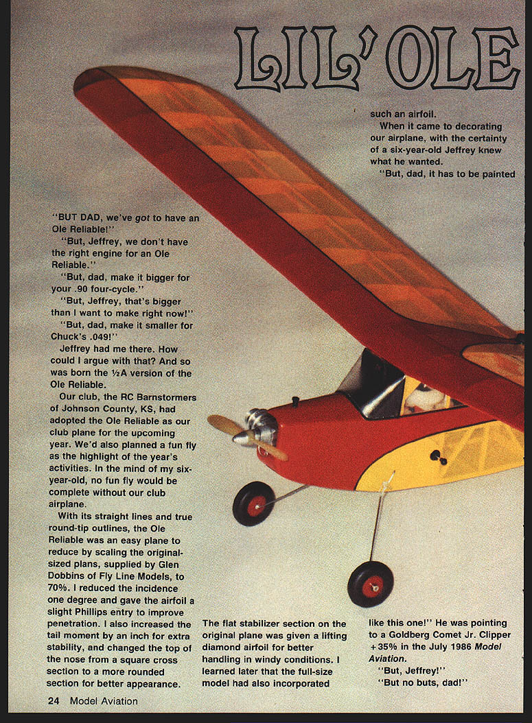
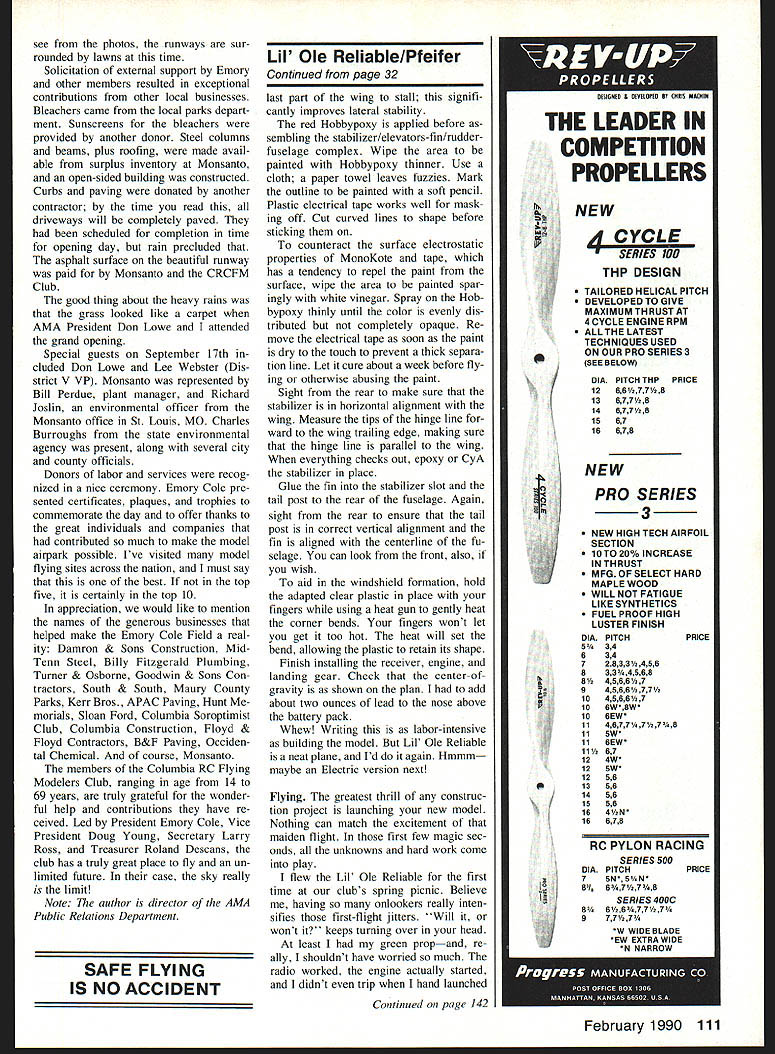
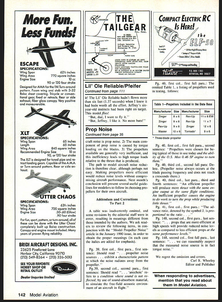
Lil' Ole Reliable
"But Dad, we've got to have an Ole Reliable!"
"But, Jeffrey, we don't have the right engine for an Ole Reliable."
"But, Dad, make it bigger for your .90 four-cycle."
"But, Jeffrey, that's bigger than I want to make right now!"
"But, Dad, make it smaller for Chuck's .049!"
Jeffrey had me there. How could I argue with that? And so was born the 1/2A version of the Ole Reliable.
Our club, the RC Barnstormers of Johnson County, KS, had adopted the Ole Reliable as our club plane for the upcoming year. We'd also planned a fun fly as the highlight of the year's activities. In the mind of my six-year-old, no fun fly would be complete without our club airplane.
With its straight lines and true round-tip outlines, the Ole Reliable was easy to reduce by scaling the original plans (supplied by Glen Dobbins of Fly Line Models) to 70%. I reduced the incidence by one degree and gave the airfoil a slight Phillips entry to improve penetration. I also increased the tail moment by an inch for extra stability and changed the top of the nose from a square cross section to a more rounded section for better appearance.
The flat stabilizer section on the original plane was given a lifting diamond airfoil for better handling in windy conditions. I later learned the full-size model had also incorporated such an airfoil.
When it came to decorating our airplane, Jeffrey knew what he wanted.
"But, Dad, it has to be painted like this one!" He was pointing to a Goldberg Comet Jr. Clipper +35% in the July 1986 Model Aviation.
"No buts, Dad!"
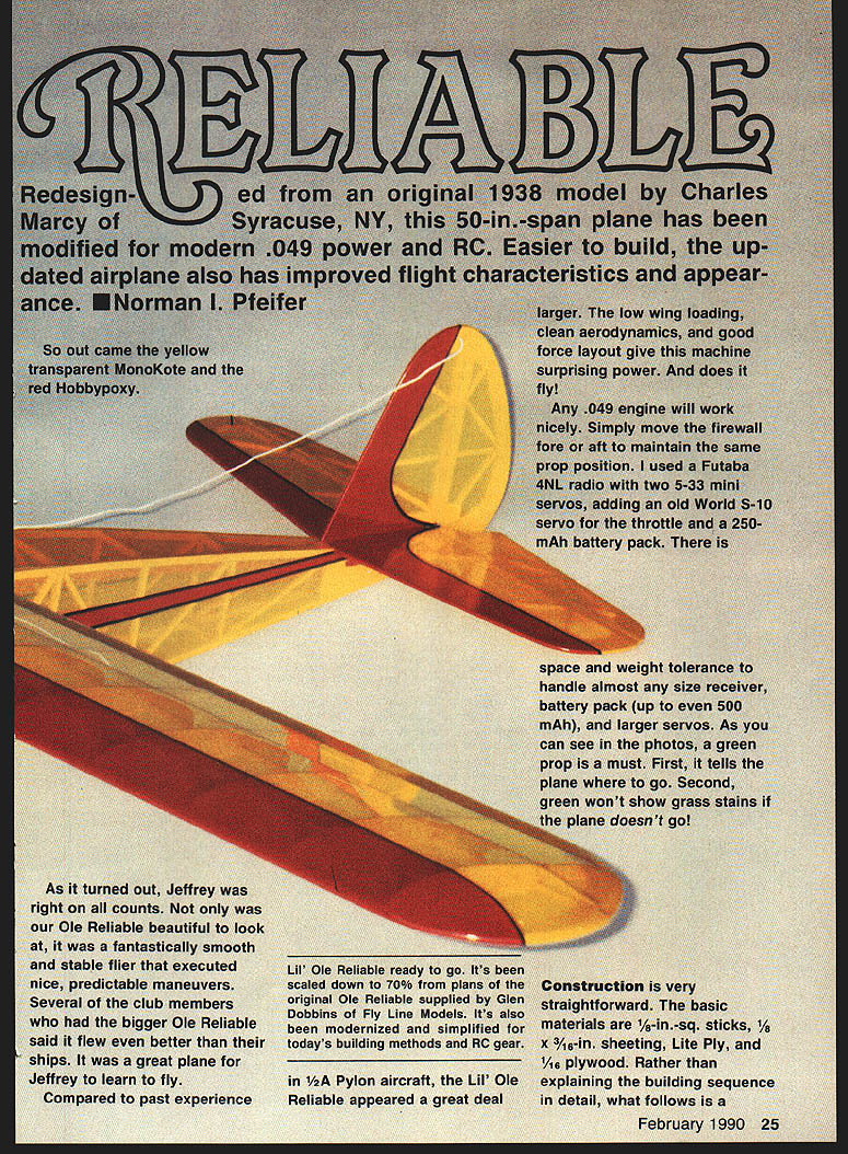
Out came the yellow transparent MonoKote and the red Hobbypoxy. Jeffrey was right: our Lil' Ole Reliable was beautiful to look at and a fantastically smooth, stable flier that executed predictable maneuvers. Several club members with larger Ole Reliables said it flew even better than their ships. It was a great plane for Jeffrey to learn to fly.
Any .049 engine will work nicely. Simply move the firewall fore or aft to maintain the same prop position. I used a Futaba 4NL radio with two 5-33 mini servos, adding an old World S-10 servo for the throttle and a 250‑mAh battery pack. There is space and weight tolerance to handle almost any receiver, battery pack (up to even 500 mAh), and larger servos. As you can see in the photos, a green prop is a must: first, it tells the plane where to go; second, green won't show grass stains if the plane doesn't go!
Lil' Ole Reliable ready to go. It's been scaled to 70% from the original Ole Reliable plans and modernized for today's building methods and RC gear.
Construction
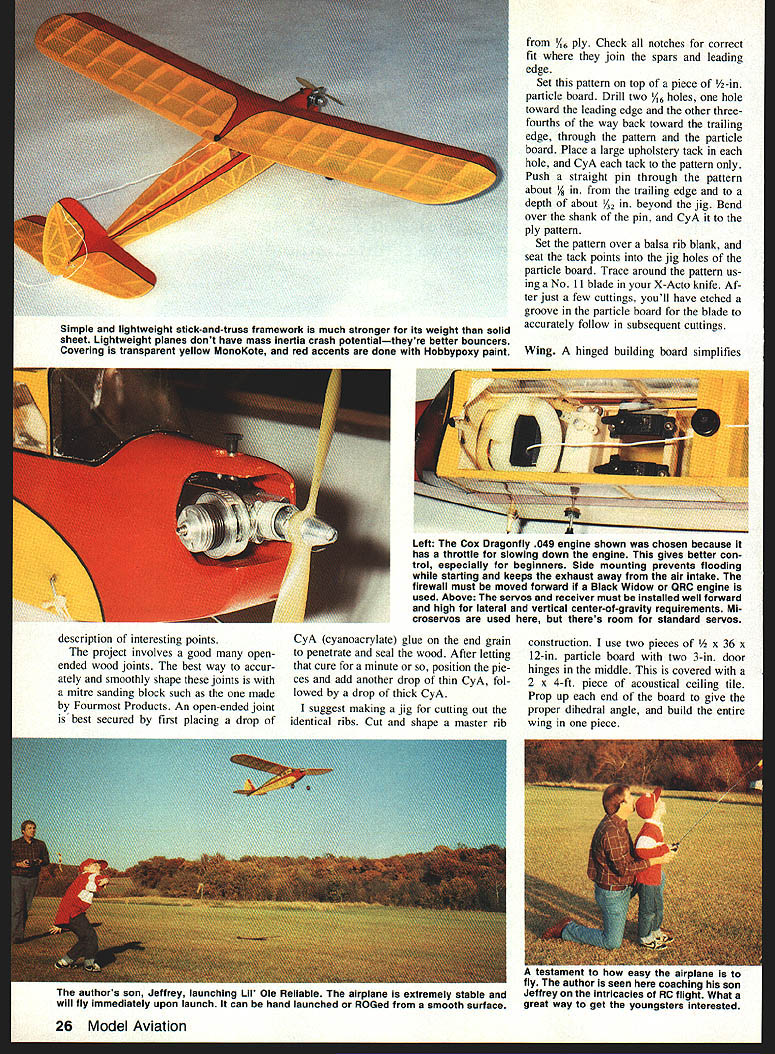
Construction is straightforward. The basic structure is a simple, lightweight stick-and-truss framework that is much stronger for its weight than a solid-sheet structure. Lightweight planes have less mass/inertia in a crash—they're better bouncers.
Materials and tools (typical)
- 1/8-in. sq. sticks
- 1/8 x 3/16-in. sheeting
- 1/16-in. ply
- Lite Ply and 1/16-in. ply firewall
- 1/8-in. sheet balsa
- 1/4-in. dowel (for wing hold-down)
- 1/8 x 1/2-in. spruce trailing-edge blocks
- 1/4-in. quarter-round cabinet molding (leading edge)
- 1/2-in. particle board for rib pattern/jig
- Acoustical ceiling tile (building board cover)
- CA (cyanoacrylate) glue — thin and thick
- Epoxy (for firewall)
- Standard hobby tools: X-Acto knife (No. 11), mitre/ miter sanding block, hacksaw blades, pins, upholstery tacks, small drill bits
Pattern and rib jig
- Set the rib pattern on 1/2-in. particle board.
- Drill two holes through the pattern and particle board: one toward the leading edge and the other about three-fourths back toward the trailing edge. Push upholstery tacks through these holes and CA the tacks to the pattern only.
- Push a straight pin through the pattern about 1/8–3/16 in. from the trailing edge; the pin tip should extend slightly beyond the jig. Bend the shank over and CA it to the ply pattern.
- Seat the pattern over a balsa rib blank, using the tack points as registration, and trace with a No. 11 blade. After a few cuts you'll have an etched groove in the particle board for accurate repeat cutting.
- Make a master rib from 1/16-in. ply and use it to cut identical ribs in a jig.
Building board
- I use two pieces of 1/2 x 36 x 12-in. particle board joined with two 3-in. door hinges. Cover with a 2 x 4-ft acoustical ceiling tile.
- Prop up each end to give the proper dihedral and build the entire wing in one piece.
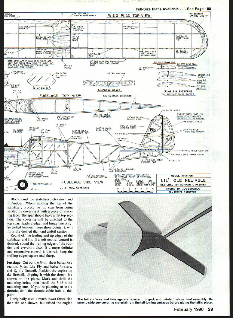
Wing
- Cut out wing parts: ribs, tips, dihedral brace, gussets, and webbing sheets.
- Trailing-edge notches are easily made with two hacksaw blades clamped together.
- Do the rear planking and bottom spars over the plans. Position the ribs and CA them in place. Install the 1/16-in. ply dihedral brace.
- Fit vertical-grained spar webs accurately with no gaps; CA in place. Note the diminishing web thickness toward the tip—this progressively disperses stress and prevents fracture at abrupt structural ends.
- Trim webbing height and CA the top spars into place.
- Use 1/4-in. quarter-round cabinet molding for the leading edge; it's strong, light, dent-proof, and already radiused. Trim the lower contour slightly after CAing it in place.
- Remove the wing from the building board. Add bottom front sheeting, a 3/16-in. dowel support block, and center 1/16-in. gussets.
- Drill a 1/4-in. hole through the dowel support block just under and behind the leading edge, angling up through the webbing above the 1/8-in. spruce bottom spar for the wing hold-down dowel. Fit the dowel but don’t glue it yet—epoxy it later after trial fitting to the fuselage and sanding.
- Fit and CA the top center planking. Block sand the wing and shape the tips. Forward of the front spar make the tips half-rounded to match the leading edge; behind the spar contour to the trailing edge thickness.
Stabilizer, fin and elevators
- Cut 1/8-in. sheet tips and rudder trailing-edge and center pieces. Pin and fit the 1/8 x 1/4-in. leading and trailing edge/hinge-line spars and add 1/8-in.-sq. balsa ribs.
- Build the fin/rudder and stabilizer/elevator flat. Leave the 3/16-in. fin slot in the center of the stabilizer.
- The most challenging part is forming the diamond-shaped lifting airfoil. The end 1/8-in.-sq. rib is notched so the spar can be trimmed and tucked at the inside edge of the 1/16-in. sheet tip, forming a tapered airfoil that transitions into a flat top for easy covering.
- Add 1/8 x 1/2-in. balsa at the center section, carrying it from in front of the spar to the leading edge and from the back edge of the spar to the hinge line. Sand evenly to create the diamond section.
- Block sand the stabilizer, elevator, and fin/rudder. Protect the top spar from sanding (cover with masking tape) so the covering will attach only to the top spar, leading edge, and hinge line. Stretched between these three points the covering will form the diamond airfoil.
- Round leading and tip edges of stabilizer and fin. For softer control round the rudder and elevator trailing edges; for more definitive response keep trailing edges square and sharp.
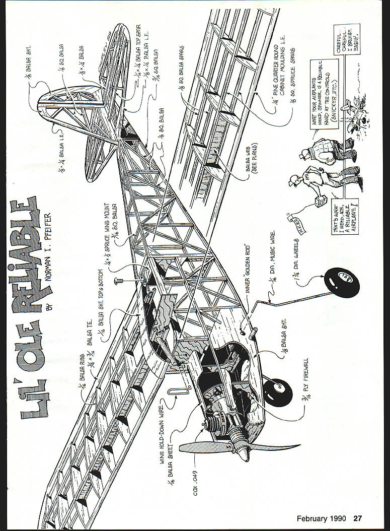
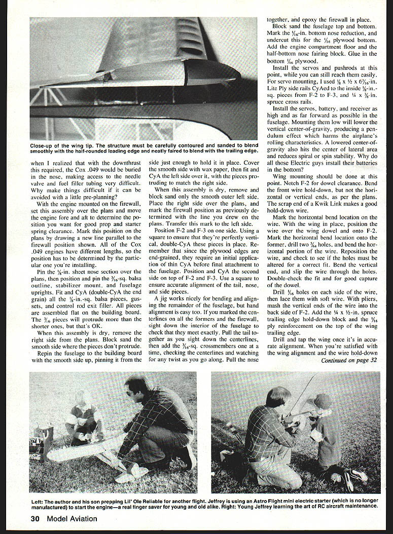
Fuselage
- Cut out the 1/8-in. sheet nose section, 1/8-in. Lite Ply and balsa formers, and 1/16-in. ply firewall.
- Position the engine on the firewall, align with the thrust line shown on the plans, mark and drill mounting holes, and install 3-48 blind nuts. If using a throttle, drill the throttle cable hole now.
- Note: different Cox .049 engines have different lengths. With the engine mounted on the firewall, set the assembly over the plans and slide the engine fore and aft to determine the desired prop and starter-spring clearance. Draw a new line on the plans parallel to the firewall to mark the chosen position.
- Pin the 1/8-in. sheet nose section over the plans. Position and pin the 3/16-in.-sq. balsa outline, stabilizer mount, and fuselage uprights. Fit and CA (double-CA the end grain) all 1/8-in.-sq. balsa pieces, gussets, and control-rod exit filler. Assemble flat on the building board.
- When dry, remove the right side from the plans and block-sand the smooth side. Repin with the smooth side up, cover it with wax paper, and fit and CA the left side over it so protruding pieces match.
- Transfer firewall position mark to the left side. Position F-2 and F-3 on one side, ensure they're perfectly vertical with a square, and double-CA them in place. CA requires an initial application of thin CA on end-grained plywood before final attachment. Position and CA the second side onto F-2 and F-3; check alignment with a square.
- Use a jig or hand alignment to bend and align the rest of the fuselage. Marked centerlines on formers and firewall help ensure everything meets exactly. Pull the tail together while adding 3/16-in.-sq. crossmembers one at a time, checking for twist. Pull the nose together and epoxy the firewall in place.
- Block-sand the fuselage top and bottom. Mark the 1/16-in. bottom nose reduction and undercut for the 1/16-in. plywood bottom. Add the engine compartment floor and half-bottom nose fairing block. Glue in the bottom 1/8-in. plywood.
- Install servos and pushrods now while access is easy. I used 5/8 x 1/2 x 6-1/2-in. Lite Ply side rails CAed to the inside 1/8-in.-sq. pieces from F-2 to F-3, and 1/4 x 3/8-in. spruce cross rails for servo mounting.
- Install servos, battery, and receiver as high and as far forward as possible. Mounting them low lowers the vertical center-of-gravity, producing a pendulum effect that harms rolling characteristics and reduces spiral/spin stability.
- Fit the wing and notch F-2 for dowel clearance. Bend the front wire hold-down per the plans but do not bend the horizontal or vertical ends until fitted. A scrap Kwik Link end can make a good hold-down.
- Mark the horizontal bend location on the wire with the wing in place, drill two 3/32-in. holes, and bend the horizontal portion. Reposition and adjust holes if necessary, then bend the vertical end and slip the wire through the holes. Drill two 1/16-in. holes on each side of the wire and lace with soft wire. With pliers mash the vertical ends into the back side of F-2.
- Add a 1/8 x 1/2-in. spruce trailing-edge hold-down block and 1/16-in. ply reinforcement on top of the wing trailing edge.
- Once alignment is correct, apply a coat of thin CA to penetrate, followed by thick CA to fillet the wire in place.
- Finish the top of the nose and the wing fairing block. Add F‑2A and 1/16-in. balsa planking. Add triangle stock pieces (modified from 3/8-in. triangle stock) and the top 3/8-in. block. Sand and shape the fuselage.
Landing gear
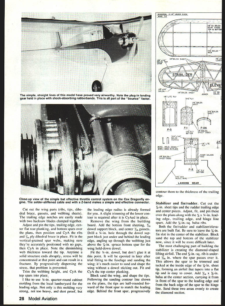
- The plug-in landing gear simplifies covering and repair. Rubber bands are good shock absorbers—on grass without rubber bands the plane would flip often; with rubber bands it flips far less. Use no more than two small light rubber bands per side.
- Bend the gear wire as shown on the plans, adjusting axle length for wheel thickness.
- Drill two holes in the fuselage sides: a 1/8-in. hole toward the top, flush with the back of F-2, and a 1/4-in. hole below it, flush with the front of F-2.
- Place a piece of yellow No. 10 inner Golden Rod through the fuselage and CA it in place to the sides and back of F-2. Choose a piece longer than needed to prevent CA from getting inside. Insert a piece of wire inside the Golden Rod and CA it to keep it straight. Trim the Golden Rod flush with the fuselage sides.
- The 1/4-in. dowel is CAed in place after covering.
Covering and final assembly
- Final sand all subassemblies until quite smooth.
- Cover the model with yellow transparent MonoKote; seams will nearly disappear.
- Use a MonoKote hinge on the elevators and rudder. On the stabilizer hinge line leave the trailing edge square; bevel the leading edge of the elevator on the bottom only (about 45°) to facilitate movement.
- Temporarily tape the top of the hinge line with masking tape to hold the elevator folded back for covering the bottom. Cover the bottom first with the elevator folded back over the hinge onto the stabilizer. Remove the temporary tape and then cover the top section with the elevator deflected down to create a good, sealed hinge.
- For painting red Hobbypoxy accents:
- Wipe the area with Hobbypoxy thinner (use a cloth, not paper towels).
- Mask with plastic electrical tape; cut curves before sticking on.
- To counteract electrostatic repulsion from MonoKote and tape, wipe sparingly with white vinegar.
- Spray Hobbypoxy thinly until color is evenly distributed but not fully opaque. Remove electrical tape as soon as paint is dry to the touch to avoid a thick separation line.
- Let paint cure about a week before flying or other abuse.
- When covering the lower portion of the tail post leave about 1/8-in. forward overhang free; after gluing the tail post the overhang is ironed onto the fuselage for a neat joint.
- Check wing and tail surfaces for warps and straighten as needed. To set washout, block up the trailing edge 1/8 in. at the tip rib, hold the wing flat to the last main rib, and heat the top covering to produce 1/8-in. washout at the tip. With washout the tips stall first, giving good aileron control at slow speed.
- Sight from the rear to ensure the stabilizer is horizontally aligned with the wing. Measure hinge-line tips forward to the wing trailing edge to confirm parallelism. When aligned, epoxy or CA the stabilizer in place.
- Glue the fin into the stabilizer slot and the tail post to the rear of the fuselage. Sight from the rear (and front if desired) to verify vertical and centerline alignment.
- To form the windshield, hold clear plastic in place and use a hair dryer to gently heat the corners; your fingers will prevent overheating. The heat sets the bends so the plastic retains its shape.
- Finish installing receiver, engine, and landing gear. Check that the center of gravity matches the plan. I had to add about two ounces of lead to the nose above the battery pack.
Power, radio, and installation notes
- Engine: any .049 will work. I chose the Cox Dragonfly .049 because it has a throttle—slowing the engine gives better control for beginners. Side mounting helps prevent flooding on starting and keeps exhaust away from the air intake.
- The Black Widow QRC engine was also used; note the firewall must be moved forward for that installation.
- When downthrust requires moving the engine, check that the needle valve and fuel-filler tubing remain accessible. Mark the desired firewall position on the plans after fitting the engine fore/aft.
- Radio/electrics: Futaba 4NL, two 5-33 mini servos (plus a World S-10 for throttle), 250‑mAh battery pack typical; room for larger batteries (up to ~500 mAh) and larger servos if desired.
- Install servos and receiver well forward and high in the fuselage to meet lateral and vertical center-of-gravity requirements. Low mounting lowers the vertical CG and worsens rolling and spiral/spin stability.
Flying
The greatest thrill is launching a newly finished plane. I flew Lil' Ole Reliable for the first time at our club's spring picnic. With many onlookers, the maiden-flight jitters were intense, but I had my green prop and things went well. The radio worked, the engine started, and I didn't trip on the hand launch. The model flew straight and level. Coordination between elevator and rudder was predictable; Lil' Ole Reliable is very docile.
The plane hadn't flown more than six feet (about 1.37 seconds) when I knew it had been worth the effort. Jeffrey's six-year-old instincts were right on target.
"But, Dad, I want to fly it."
"But, Jeffrey, I like it. No more buts!"
Transcribed from original scans by AI. Minor OCR errors may remain.

