
Limitation
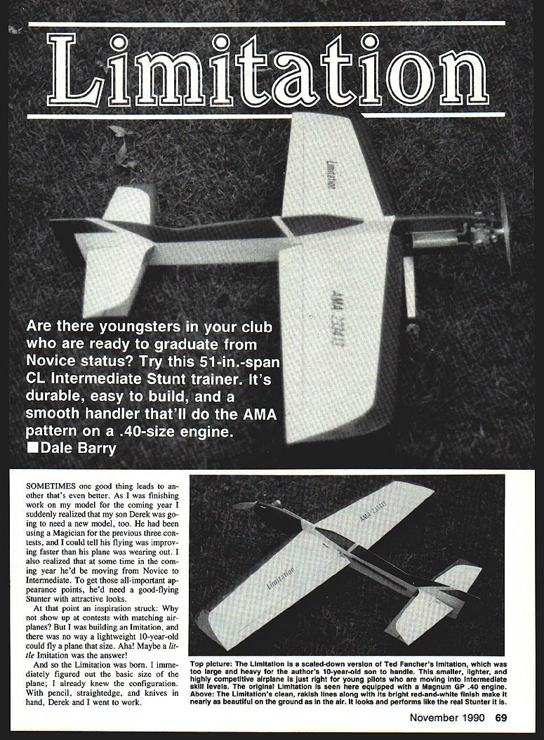
Are there youngsters in your club who are ready to graduate from Novice status? Try this 51-in.-span CL intermediate stunt trainer. It's durable, easy to build, and a smooth handler that'll do the AMA pattern on a .40-size engine.
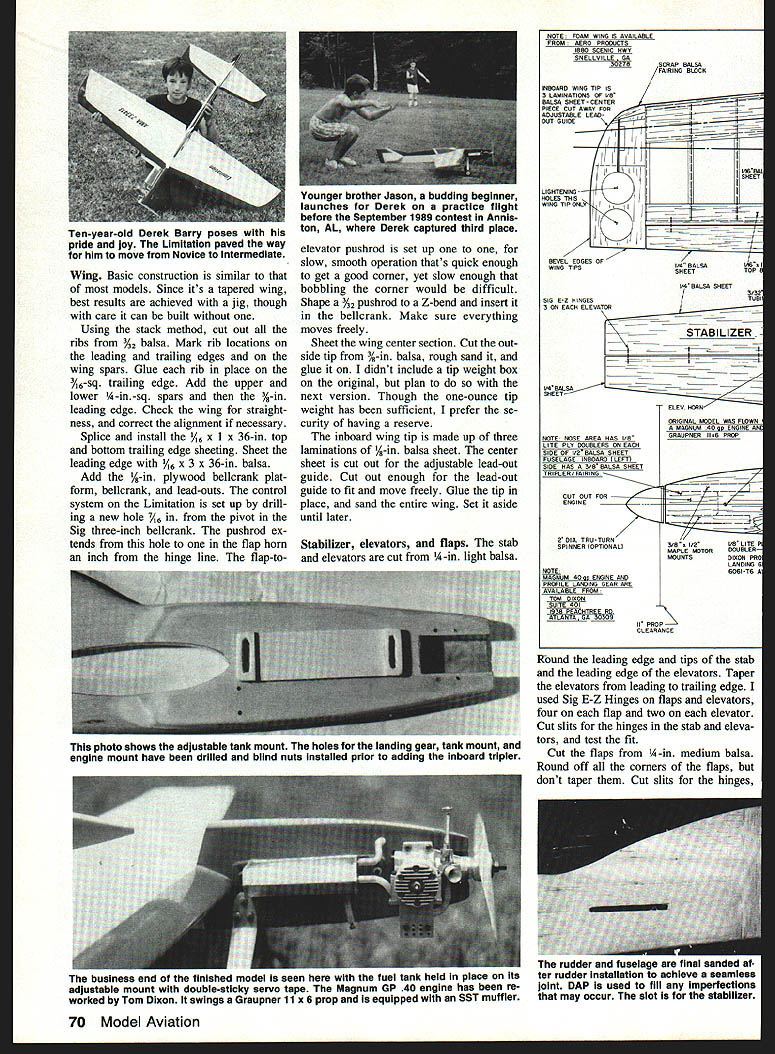
SOMETIMES one good thing leads to another that's even better. As I was finishing work on my model for the coming year I suddenly realized that my son Derek was going to need a new model, too. He had been using a Magician for the previous three contests, and I could tell his flying was improving faster than his plane was wearing out. I also realized that at some time in the coming year he'd be moving from Novice to Intermediate. To get those all-important appearance points, he'd need a good-flying stunter with attractive looks.
At that point an inspiration struck: why not show up at contests with matching airplanes? But I was building an Imitation, and there was no way a lightweight 10-year-old could fly a plane that size. Aha — maybe a little Imitation was the answer!
And so the Limitation was born. I immediately figured out the basic size of the plane; I already knew the configuration. With pencil, straightedge, and knives in hand, Derek and I went to work.
Wing
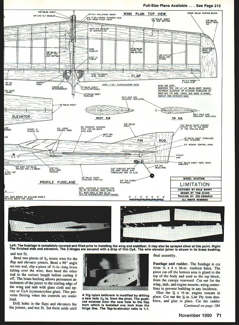
Basic construction is similar to that of most models. Since it's a tapered wing, best results are achieved with a jig, though with care it can be built without one.
Using the stack method, cut out all the ribs from 3/32-in. balsa. Mark rib locations on the leading and trailing edges and on the wing spars. Glue each rib in place on the 3/16-in.-sq. trailing edge. Add the upper and lower 1/4-in.-sq. spars and the 3/16-in. leading edge. Check the wing for straightness and correct the alignment if necessary.
Splice and install the 1/16 x 1 x 36-in. top and bottom trailing-edge sheeting. Sheet the leading edge with 1/16 x 3 x 36-in. balsa. Add the 1/4-in. plywood bellcrank platform, bellcrank, and lead-outs. The control system on the Limitation is set up by drilling a new hole 7/64 in. from the pivot in the Sig 3-inch bellcrank. The pushrod extends from this hole to one in the flap horn an inch from the hinge line. The flap-to-elevator pushrod is set up one-to-one for slow, smooth operation that's quick enough to get a good corner, yet slow enough that bobbling the corner would be difficult.
Shape a 3/32-in. pushrod to a Z-bend and insert it in the bellcrank. Make sure everything moves freely.
Sheet the wing center section. Cut the outside tip from 3/8-in. balsa, rough-sand it, and glue it on. I didn't include a tip weight box on the original, but plan to do so with the next version. Though the one-ounce tip weight has been sufficient, I prefer the security of having a reserve.
The inboard wing tip is made up of three laminations of 1/8-in. balsa sheet. The center sheet is cut out for the adjustable lead-out guide — cut out enough for the lead-out guide to fit and move freely. Glue the tip in place, and sand the entire wing. Set it aside until later.
Stabilizer, elevators, and flaps
The stab and elevators are cut from 1/4-in. light balsa.
Round the leading edge and tips of the stab and the leading edge of the elevators. Taper the elevators from leading to trailing edge. I used Sig E-Z Hinges on flaps and elevators — four on each flap and two on each elevator. Cut slits for the hinges in the stab and elevators, and test the fit.
Cut the flaps from 1/4-in. medium balsa. Round off all the corners of the flaps, but don't taper them. Cut slits for the hinges.
Bend two pieces of 3/32-in. music wire for the flap and elevator joiners. Bend a 90° angle on one end, slip a piece of 1/8-in.-long brass tubing over the wire, then bend the other end to the correct length before cutting it off. The brass bushing allows permanent attachment of the joiner to the trailing edge of the wing and stab with glass cloth and epoxy or CyA (cyanoacrylate glue). This prevents flexing when the controls are under load.
Drill holes in the flaps and elevators for the joiners, and test fit. Set them aside until final assembly.
A Sig nylon bellcrank is modified by drilling a new hole 1/8 in. from the pivot. The pushrod extends from the new hole to the flap horn, which is installed one inch from the hinge line. The flap-to-elevator ratio is 1:1.
Fuselage and rudder
The fuselage is cut from 1/2 x 4 x 36-in. medium balsa. The piece cut off the bottom area is glued to the top of the body and used as the top block from the canopy rearward. Cut out for the wing, stab, and engine mounts, using centerlines to prevent building in any incidence.
Glue the 3/8 x 1/2-in. engine mounts in place. Cut out the 1/8-in. Lite Ply nose doublers, and glue them in place. Glue a piece of 1/8-in. light balsa across the body from the inside to the outside rear to build in offset. Shape the rudder, canopy, and outboard doubler into the body.
If you plan to use an adjustable tank — and I recommend doing so — make a tank from 1/8-in. Lite Ply with doublers at each end. Cut vertical slots in the ends to fit 4-40 bolts. Mark a position on the outboard doubler to allow equal up-and-down adjustment, drill holes, and install the blind nuts.
If you're careful with wood selection, a .35-size engine will fly the Limitation fine. However, I chose a Magnum GP .40, modified for CL by Tom Dixon (Suite 401, 1938 Peachtree Rd., Atlanta, GA 30309). The GP .40 is a great substitute for the Fox .35. It's more powerful, has less vibration, offers good two-/four-cycle reliability, and will do the entire AMA pattern on 2-1/2 oz. of fuel. No, that's not a misprint — my three GP .40s all do the pattern on from 2-1/4 to 2-3/4 oz. of fuel.
At this point a decision on the landing gear must be made. If you're going to use a 1/8-in. wire gear, make and install it now. I use a profile aluminum gear from Tom Dixon. It's lightweight and doesn't flex. Flexing in wire gear can cause bounce while landing. The aluminum gear is also removable, which is very helpful when you're loading the airplane in the back of a minivan. The gear can be installed during final assembly.
Cut a nose tripper from 1/8-in. balsa. Glue the tripper to the inboard side of the fuselage, where it adds strength to the fuselage joint. The nose tripper also hides the blind nuts and allows you to shape the nose into a spinner.
Thoroughly sand and shape the entire fuselage. Cover it with silkspan or 1/2-oz. glass cloth.
Assembly and finishing
Assemble. Trial-fit the wing and stab, sanding wherever necessary. The fit doesn't have to be perfectly snug; keeping the wing and tail in line with zero degrees incidence is what matters. Slide the wing most of the way into the body, and permanently install the tank and engine. Install the bellcrank, leadouts, and control linkages, and make final adjustments to balance and control throws before test flying.
Glue the flap joiner to the center of the trailing edge. Apply slow-curing epoxy to the center of the wing, and slide it all the way into the body. Continually check alignment while the epoxy sets, making certain that the wing is 90° to the body when viewed from in front and above.
After the wing has dried, follow the same steps for the stabilizer. Be sure the stab is parallel to the wing and that they are equidistant from hinge line to hinge line all the way across. Install the flaps and elevators.
Covering and finishing: when all the glue joints are dry, cover the entire model with silkspan. Apply five to ten coats of clear nitrate dope, lightly sanding off fuzz between the first two coats. Form fillets with Epoxolite. When the Epoxolite is dry, sand it smooth and brush on a coat of nitrate clear so the paint will adhere properly.
Spray the entire model silver. Allow a few days for drying, then sand off the silver everywhere but over the rib bays. This will reveal all the dings and dents to be filled and resanded. Spray the entire model silver again, and you're ready to apply color.
I sprayed the entire plane with Sig white dope, mixed with raw white pigment from Pro Stunt Products (9 Union Ave., Little Ferry, NJ 07643). This pigment allows white to cover anything two or three times faster than normal. After the dope had dried, I sprayed on the red trim and then the gray/black canopy. Finally, a quart of thinned clear Lite-Coat was sprayed over the entire model and allowed to dry.
When all painting is complete, install the control horns, pushrod, wheels and landing gear, tank, etc. My Limitation prototype came out at 43 oz. ready to fly. With a better selection of wood, you can easily build it considerably lighter.
Flying results and contact
Derek has used the Limitation in two contests at this writing. The model had only five flights on it when my son took first place in Novice at the spring 1989 contest in Marietta, GA. A little over a month later Derek took second place in his first outing as an Intermediate, in Cincinnati.
This stunt trainer looks good in the air, handles smoothly, turns well, and is fun to fly. Build one and find out. Please write with any questions you might have:
Dale Barry Rt. 2, Box 264D2 Harlem, GA 30814
Transcribed from original scans by AI. Minor OCR errors may remain.

