
A Little History
Aeronca: A Photo History by Hollenbaugh and House is highly recommended to anyone with an interest in Aeroncas. This delightful soft-cover book includes an excellent section on the numerous variations of the T (trainer) series. This was Aeronca's first tandem-seat aircraft, and their first design with a four-longeron box fuselage and aluminum wing ribs.
When the threat of war became apparent in 1939, the US military had a serious shortage of aircraft and an even more alarming undersupply of pilots. The government instituted an emergency program to train a pool of civilians in the basic piloting skills to be activated as aviation cadets when the military training programs were developed.
This program was called Civilian Pilot Training (CPT). It contracted with operators of private pilot training facilities for flight instruction, and with colleges and universities to conduct ground schools. Suddenly, many grass-strip operations went from near-starvation to being overwhelmed with students.
There were very few pilot training operations with large enough facilities or an inventory of suitable training aircraft. Emergency contracts for the production of tandem-seat light training aircraft were issued. The US light-plane industry responded by expanding what few facilities it had and by adding newly designed aircraft.
Actually, there were very few suitable stock aircraft designs anyway. Only Piper had the ability to manufacture more than a few tandem trainers per month. Rearwin, Porterfield, Cessna, Beech, Ryan, Fairchild, etc. had no tandem designs or were producing heavier and higher-powered trainers for the military.
Into this shortage Aeronca introduced the Model T, with the prototype completed February 27, 1940. The design used tail surfaces from the Aeronca Chief and many existing parts from other products.
It was first designated Model T-65 (with a letter corresponding to the engine manufacturer); when the Civilian Pilot Training program came into effect, the designation was changed to TA Defender. Many CPT pilots who first flew in Defenders went on to active military duty and were among the first to complete aviation cadet training programs.
In military use the designation became YO-52, then L-3 (the version I saw on the golf course). Further refinements led to O-58 and L-3A, B, and C designations. The Defender also became the Grasshopper, with a delightful logo designed by Walt Disney.
After the CPT program had completed its mission, a shortage of suitable larger military trainers for the graduates logically developed, so Aeronca then built Fairchild PT-19s and PT-23s under license.
D. B. Mathew
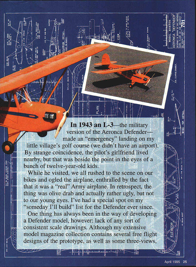
In 1943 an L-3 — the military version of the Aeronca Defender — made an "emergency" landing on my little village's golf course (we didn't have an airport). By strange coincidence, the pilot's girlfriend lived nearby, but that was beside the point in the eyes of a bunch of twelve-year-old kids.
While he visited, we all rushed to the scene on our bikes and ogled the airplane, enthralled by the fact that it was a "real" Army airplane. In retrospect, the thing was olive drab and actually rather ugly, but not to our young eyes. I've had a special spot on my "someday I'll build" list for the Defender ever since.
One thing has always been in the way of developing a Defender model, however: lack of any sort of consistent scale drawings. Although my extensive model-magazine collection contains several free-flight designs of the prototype, as well as some three-views, none of them agree. Perhaps the confusion lies in the numerous variations and identifying numbers, or maybe those free-flight designs were done without three-views.
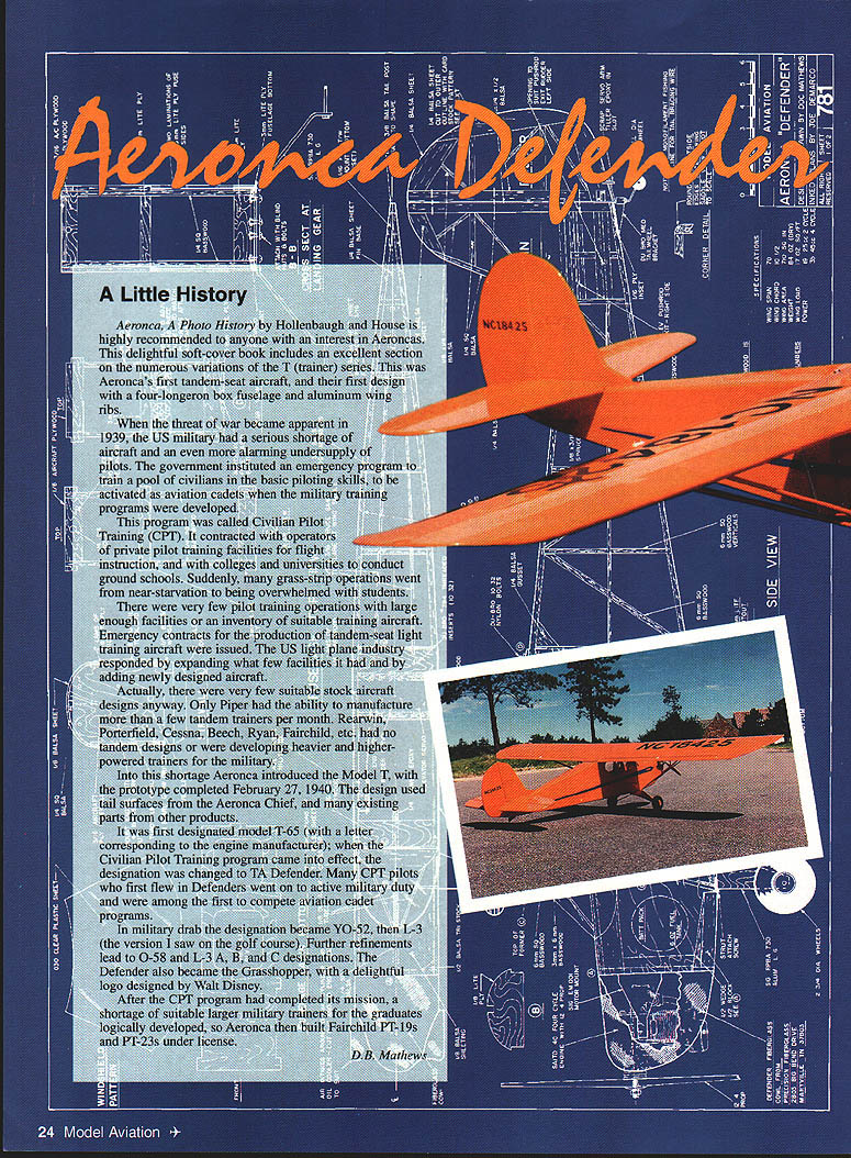
Several years ago I encountered and photographed a delightful orange Defender at Oshkosh, and it set off the desire to finally design and build the model. I wrote to Walt Mooney, asking if he had anything of reasonable reliability on Aeroncas, since he had published several. Walt sent copies of everything he had (most of which duplicated my own material), but he did include a 1941 Aircraft Yearbook drawing, which seems to most closely match the available photos.
In the style of Mooney, the design presented here is not super-scale; compromises have been made in the name of simplicity and flyability. Yet even a casual glance immediately identifies the prototype. Just a few simple touches of scale detail add a lot of charm and "cuteness" to the model without adversely affecting its excellent flying traits (or working the builder to death).
Construction
Materials and adhesives
- Our prototype used some metric-sized basswood in the fuselage. Arrangements have been made with Riley Wooten's Lone Star Balsa (800-687-5555) for a stripwood package.
- Alternately, sand down 1/4" basswood stock to the 6 mm size needed to match the two layers of 3 mm Lite Ply of the fuselage sides. (Although commonly referred to as 1/8 Lite Ply, the material is actually 3 mm thick.)
- Glue balsa-to-hardwood joints with aliphatic resin such as Sig Bond or Titebond.
- Epoxy all hardwood-to-plywood and plywood-to-plywood joints.
- Cyanoacrylate (CyA) adhesives are fine for the remainder of the project.
No unusual tools are required, but a jig saw (Dremel, etc.) or bandsaw is convenient.
Landing gear and cowl
The metal landing gear works very well and is both sturdy and easily maintained. Attach the plywood plates by coarse-sanding them, etching the aluminum with citric acid (lemon juice), and adhering the plywood fairings with thick CyA. If preferred, the bent-wire gear system used in Sig's 1/6 J-3 Cub kit will adapt well.
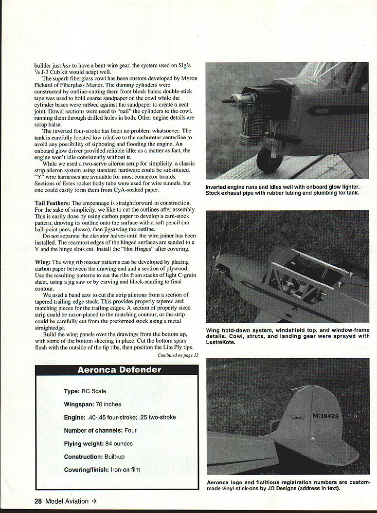
A superb fiberglass cowl has been custom-developed by Myron Pickard. Fiberglass master dummy cylinders are constructed by outline-cutting a block of balsa. Double-stick tape holds coarse sandpaper while the cowl cylinder bases are rubbed against it to create a neat joint. Dowel sections pin the cylinders to the cowl through drilled holes. Other engine details are formed from scrap balsa.
An inverted four-stroke has no problem whatsoever. The fuel tank is carefully located low relative to the carburetor centerline to avoid siphoning and flooding the engine. An on-board glow driver provided a reliable idle; in fact, the engine would not idle consistently without it.
Control system
- A two-servo aileron setup was used for simplicity. A classic strip-aileron system using standard hardware could be substituted.
- Y-harnesses and available connector brands simplify the wiring.
- Sections of Estes rocket body tube were used as wire tunnels; CyA-soaked paper tubes are a simple alternative.
Tail and empennage
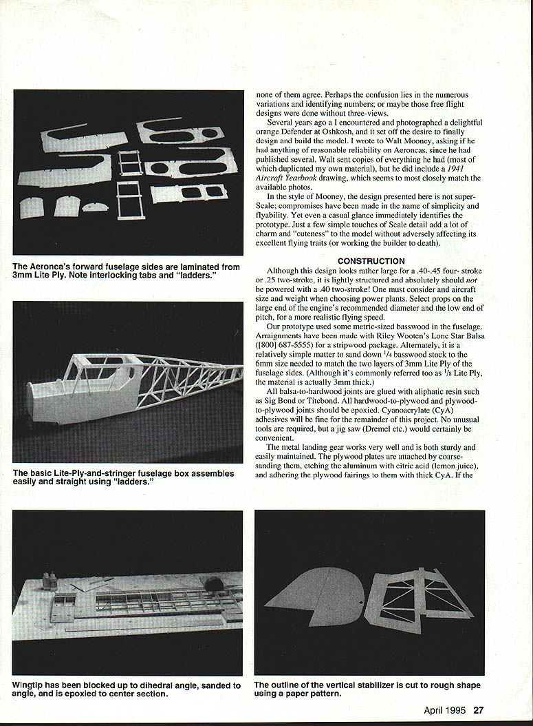
The tail feathers and empennage are straightforward. For simplicity, cut the outlines after assembly by developing a card-stock pattern with carbon paper and transferring it with a soft pencil. Jig-saw the outline and separate the elevator halves only after the wire joiner has been installed. Sand the rearmost edges of the hinged surfaces to a V and cut hinge slots. Install Hot Hinges after covering.
Wing ribs and ailerons
- Develop wing-rib master patterns by placing carbon paper between the drawing and section plywood.
- Use the resulting patterns to cut ribs in stacks from light C-grain sheet using a jig saw, then carve and block-sand to the final contour.
- The strip ailerons were cut from a section of tapered trailing-edge stock using a bandsaw. This provides properly tapered and matching pieces. Alternatively, razor-plane a properly sized strip or carefully cut from preformed stock using a metal straightedge.
Wing assembly
Build the wing panels over the drawings from the bottom up, with some bottom sheeting in place. Cut the bottom spars flush with the outside of the tip ribs, then position the Lite Ply tips.
Cut the top spar extension fillers to match the angle. The center section is built integrally with the right wing, then cut and removed. Space should be left in the top and bottom center-section sheeting to provide access when the "grabber" is installed onto the fuselage hold-down dowel in a later step.
By tilting the inside ribs using the jig, block up the wing panel and sand in the bevel using a table edge and sanding block. This creates a tight joint and requires a minimum of epoxy.
No dihedral gussets were shown on the plans; tight joints combined with epoxy and glass cloth provide superior strength. After the panels have been epoxied together at the rib faces and the "grabber" installed, simply wrap glass and epoxy over the joint.
Rough-sand the leading-edge and tip filler blocks to outline, then finish-sand after the wing is complete.
Fuselage construction
- Develop the fuselage sides using the carbon-paper transfer technique. Note the inside sections have lightening holes.
- Build the sides one atop the other, using scraps of masking tape to keep them from sticking. Fit triangular stock and some gussets after separation. Be sure to build a left and right side!
- Fabricate the "ladders" directly over the drawings. Locate and drill all holes at this time.
Engine and cowling installation
Rough-position the engine in the cowl by laying the engine and mount into it, cutting the appropriate shaft-exit and head-passage holes in the fiberglass unit, then placing the mount onto the precut firewall and adjusting to match the cowl.
When satisfied, spot-glue the mount to the firewall with CyA, remove the cowl, and mark and drill the proper holes for the mounting bolts and blind nuts. Drill other required holes in the firewall at this time.
As with any cowl-mounted engine, there should be a much larger total exit than entry for the cooling air. I cut a hole in the cowl bottom approximately the size of the cylinder head. Entry air is routed through the scale locations and by clearing some glass around the dummy cylinders.
Fuselage assembly and alignment
- Pin the right fuselage side flat over the side view, install the four major forward sections, check for squareness in all planes with a triangle, then join them using medium CyA.
- Insert the left side onto the bulkheads, check for squareness in all planes, then adhere.
- The completed forward fuselage basic box should be strong and true.
Block up the tail post half the fuselage width at the midline and pull the left post down onto the right. Use two clothespins to hold this joint while you check alignment, then CyA the tail post together.
Balsa crosspieces are cut in pairs over the top view and glued in place with the fuselage still pinned down.
The hardwood cabin crossmembers, gussets, etc., should now be added. Moisten the sheeting for the tank area with diluted ammonia, pull it over formers A and B, then release and flow medium CyA on the joints while pulling the sheet down from the sides toward the center strip.
Use a steel straightedge to cut the sheeting, covering half of the center strip. Repeat for the other half, trimming the second sheet until it fits tightly against the first.
The windscreen top is formed of two cross-grain precut pieces of balsa moistened with diluted ammonia and clamped against the bottom of the forward section of the wing. Use masking tape to hold them in place while they dry. Glue the halves together with aliphatic resin and tape them again to the underside of the wing center section. Install onto the fuselage with epoxy.
The three braces inside the windscreen are purely fake: sections of 1/8" aluminum tubing CyAed into holes in the balsa coaming and the windscreen-top unit.
Epoxy the 1/4" dowel onto the front crossmember with the fuselage inverted. This needs to be centered and parallel with the sides.
Wing attachment and landing gear
Place the assembled wing onto the saddles and check alignment using the classic pin-and-string-at-the-tailpost method. Drill the trailing-edge basswood down into the rear crosspiece of the fuselage. Remove the wing and either tap the rear bass for nylon bolts or use threaded inserts.
Bolt the wing onto the fuselage, place the "grabber" flush against the front wing spars using clothespins to hold it. Adjust the grabber for a tight fit into the wing saddle. Epoxy the grabber to the front wing spars, then finish-sheet the center section.
Use the preformed Sig aluminum gear to mark the landing-gear mount for the proper holes and blind nuts. Although not terribly scale, Du-Bro axles work well to mount the wheels. Hubcaps can be made by scribing and popping out the bottoms of aluminum soft-drink cans to the desired diameter and adhering them to the wheel hubs with RC-56 adhesive.
Radio installation, pushrods and stringers
- Radio installation utilizes 3/8" square bass crossmembers for the servos exposed to the pilot. Install the ply sides. The battery pack and fuel tank fit nicely inside the forward compartment; keep the tank as low as possible with an inverted engine.
- Flexible nylon-tube pushrods were used for rudder and elevator, and cable for the throttle. Rough up the pushrods at the point they pass through anti-friction mounts and the tail exit for better adhesion of CyA.
- Spruce side and top contour stringers are glued in the locations shown, blocks sanded to blend them into the sides.
- The 1/4" plywood window frames are larger than the underlying Lite Ply and stringers to provide a sill into which the clear plastic can be adhered with RC-56, using a spot of CyA after the fuselage has been covered.
The side windows are developed by scoring the plastic to the proper outline and breaking at the score marks — do not try to cut through the plastic!
The windscreen will require some trimming to fit perfectly. Install it by cutting a narrow strip of covering material away from the bottom border, slipping the windscreen into the sills, and adhering all edges with RC-56. Use strips of masking tape to hold everything in place overnight. Dress the edges with trim tape as needed.
Struts
Struts are assembled over the drawing using epoxy. Cut slots for the nylon landing-gear straps and Goldberg snap fittings. Sand the struts to an airfoil shape. CyA the straps and fittings into the slots.
Wire jury struts held with female halves of Robart mini hinges can be used, but they were not durable in my experience. The fuselage ends of the struts are snapped into screws mounted just forward of the landing gear; the straps let the struts flex slightly and snap in easily.
Finish
This design benefits from the torsional strength added by stiffer iron-on coverings such as MonoKote, UltraCote, or Oracover.
I sprayed the cowl, wing struts, and landing gear with MonoKote LusterKote, but any matching paint is fine. Black and silver hobby enamels were used on the dummy engines.
For ideas on color and markings variations, contact Bob Banka's Scale Model Research, 3114 Yukon Ave., Costa Mesa, CA 92626 for color photo packs.
The neat Aeronca logo for the tail and the numbers are available from JOE Designs, Rt. 1 Box 225 AAA, Stratford, OK 74672.
Aeronca Defender
- Type: RC Scale
- Wingspan: 70 inches
- Engine: .40–.45 four-stroke; .25 two-stroke
- Number of channels: Four
- Flying weight: 84 ounces
- Construction: Built-up
- Covering/finish: Iron-on film
Flying
If you've ever flown an RC-assist Old-Timer or a lightly loaded high-wing trainer, you'll know what to expect.
The Defender is very light and will take off with virtually no forward roll. There is a tendency for the nose to tuck down when the throttle is slammed open, so bring the throttle up slowly. Feed in only enough up elevator to keep the model level; apply judicious amounts of right rudder and the model will take off very realistically. If too much up is applied, the Defender will be airborne before you are ready.
No thrust settings are shown on the drawings due to alignment variations in construction and wide variations in power and prop combinations.
With a .40 four-stroke and an 11 x 5 prop, the positive incidence built into the wing seems to provide sufficient downthrust. Just a tad of right thrust was used. If a .25 two-stroke and a 9 x 6 prop are used, be prepared to add at least three degrees of down and right thrust.
The .40 four-stroke is run at about half throttle most of the time for casual flying. The model will climb briskly at full throttle and the recommended control throws will be excessive in full-throttle level flight.
Landing is the main challenge: slowing the model enough to stop it from flying. Line it up, cut to low throttle well out, and let it float down. In any breeze, use wheel landings. The Defender is almost easier to land dead-stick; it is a floater, with no tendency to stall and snap.
This is plain old-fashioned flying for fun. The Defender is an attractive alternative to the plethora of Cubs, and has distinctive cuteness and delightful flying characteristics all its own. The Defender was worth the long gestation period, as it is truly an easy model to enjoy!
This article is dedicated to the memory of Walt Mooney. Though Walt is deceased, his legacy of simply built but highly flyable model-airplane designs lives on. Hopefully, this design embodies the spirit of his models.
Transcribed from original scans by AI. Minor OCR errors may remain.

