
little white mouse
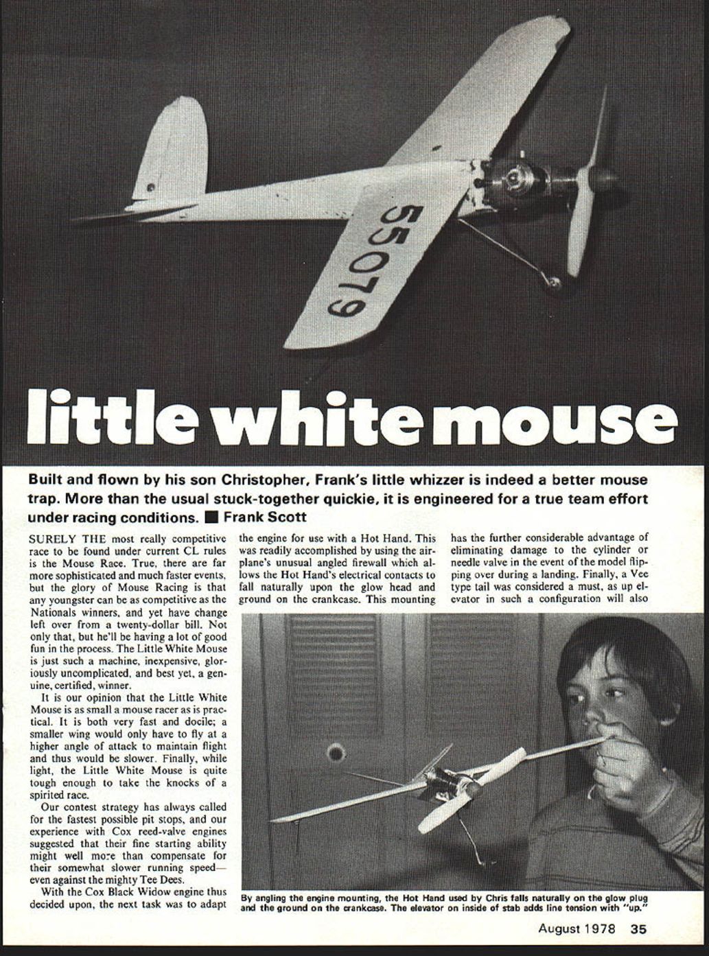
Built and flown by his son Christopher, Frank's little whizzer is indeed a better mouse trap. More than the usual stuck-together quickie, it is engineered for a true team effort under racing conditions. ■ Frank Scott
SURELY THE most really competitive race to be found under current CL rules is the Mouse Race. True, there are far more sophisticated and much faster events, but the glory of Mouse Racing is that any youngster can be as competitive as the Nationals winners, and yet have change left over from a twenty-dollar bill. Not only that, but he'll be having a lot of good fun in the process. The Little White Mouse is just such a machine, inexpensive, gloriously uncomplicated, and best yet, a genuine, certified, winner.
It is our opinion that the Little White Mouse is as small a mouse racer as is practical. It is both very fast and docile; a smaller wing would only have to fly at a higher angle of attack to maintain flight and thus would be slower. Finally, while light, the Little White Mouse is quite tough enough to take the knocks of a spirited race.
Our contest strategy has always called for the fastest possible pit stops, and our experience with Cox reed-valve engines suggested that their fine starting ability might well more than compensate for their somewhat slower running speed—even against the mighty Tee Dees.
With the Cox Black Widow engine thus decided upon, the next task was to adapt the engine for use with a Hot Hand. This was readily accomplished by using the airplane's unusual angled firewall which allows the Hot Hand's electrical contacts to fall naturally upon the glow head and ground on the crankcase. This mounting has the further considerable advantage of eliminating damage to the cylinder or needle valve in the event of the model flipping over during a landing. Finally, a Vee type tail was considered a must, as up elevator in such a configuration will also add an out-rudder force component very useful in maintaining line tension during takeoffs and landings.
Construction is easily begun by gluing the fuselage pieces to a 1/4 sq. spruce fuselage spine. Assembly used fast-curing epoxy glue throughout. The landing gear is next bent to shape and assembled. The three-piece firewall and blind mounting nuts for the engine should also be installed at this time. The wing is shaped from firm 1/8" balsa; the airfoil has a flat bottom and a rather sharp leading edge. After the wing has been sanded quite smooth, glue the plywood bellcrank mount in place. The triangular mount, largely responsible for the model's strength, should be glued to the wing and to the fuselage at the firewall to attach the model. Note the wing root leading edge is shaped to provide an out-thrust angle. Firewall experiments with engine offset have found a perceptible decrease in speed, yet handling, especially during takeoff, is markedly improved.
Tail surfaces are cut to shape from 1/16" basswood and carefully sanded to a streamline section. The single elevator is hinged with fabric hinges in the traditional manner used on the stabilizer. Shallow grooves are cut in the fuselage just above the spruce spine to assist in aligning stabilizers; these are then epoxied in place. A dihedral template (see plan) may assist in establishing the angle during assembly.
A single landing gear strut is barely adequate for the job. Consequently, a brace of 1/16" wire is recommended; bind the wire and solder the main strut to the rear end strut, epoxying the fuselage joint and reinforcing with a fabric patch. Small triangular hardwood blocks epoxied in place reinforce the critical firewall-fuselage joint; alternatively, Epoxylite fillets will also serve very well. The tail skid is bent to shape, secured with glue and a fabric patch. A plywood right wing tip skid mounting plate should also be installed at this time.
Give the model a good overall sanding and inspect carefully for sound construction before applying finish. As a competition model, use the maximum amount of elbow grease sanding and the minimum amount of paint—you want a smooth, light weight. So far as finish is concerned, we recommend epoxy-type paint being durable against both fuel and bumps. White was chosen for visibility, since we often practice in the evening; other colors tend to disappear at twilight.
The wing-tip skid is secured at the tip with reinforcement from a small woodscrew. A plastic leadout guide is glued in position at the left wing tip. After installation of the control system, it would be well to lock the screws and nuts securing the bellcrank and elevator horn.
Hot Stuff
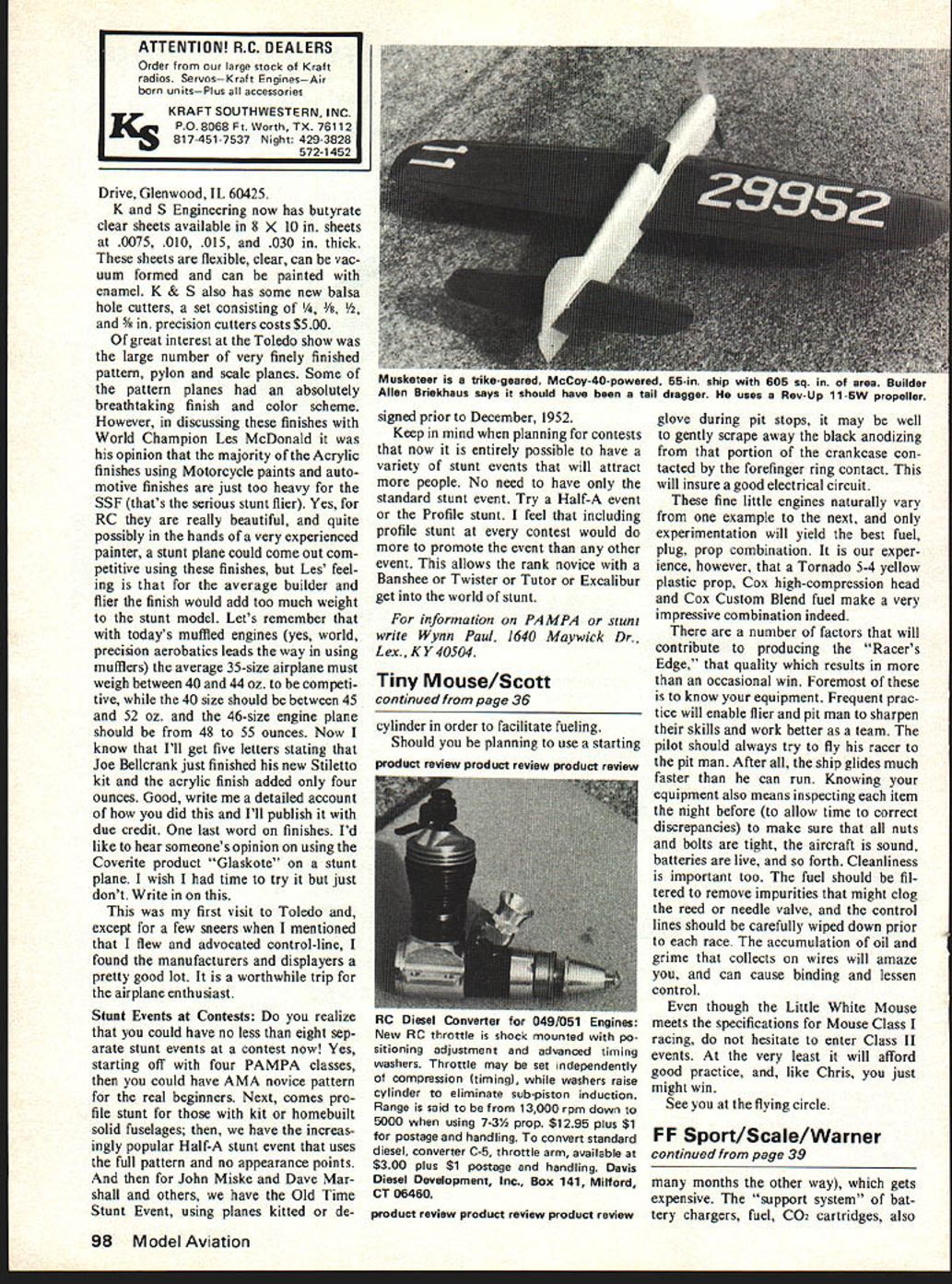
Before mounting the engine, remove the fuel tank back plate and move the fuel pickup tube within so it will be able to pick up fuel properly with the engine mounted on a slant. In this regard we have found it useful to actually wire the fuel line to the nearest fuel tank screw. The fuel tank body should be rotated so the vents are 90 degrees. provide an "out" rudder force component so very useful in maintaining line tension during takeoffs and landings.
Construction is most easily begun by gluing firm 1/4" balsa fuselage pieces to the 1/4" sq. spruce fuselage spine. For assembly, we used a fast curing epoxy glue throughout. The landing gear is next bent to shape and assembled into the three-piece firewall. Blind mounting nuts for the engine should also be installed at this time.
The wing is shaped from firm 1/4" sheet balsa. Our airfoil has a flat bottom and rather sharp leading edge. After the wing has been sanded quite smooth, it is glued to the plywood bellcrank mount. This triangular mount is largely responsible for the model's strength and should not be changed. The wing then can be assembled to the fuselage, and the firewall then attached to the model. Note that the wing root leading edge is shaped so as to provide an out-thrust angle to the firewall. In our experiments with engine offset, we have not found any perceptible decrease in speed, yet handling, especially during takeoff, is markedly improved.
The tail surfaces are cut to shape from 1/16" bass wood and carefully sanded to a streamline section. The single elevator is hinged with fabric hinges in the traditional manner, and is used only on the left stabilizer.
Shallow grooves are cut in the fuselage just above the spruce spine to assist in aligning the stabilizers when they are epoxied in place. The dihedral template on the plan may assist in establishing this angle during assembly.
A single landing gear strut is only barely adequate for the job. Consequently, it is recommended that a brace be bent of 1/16" wire and then bound with wire and soldered to the main strut. The rear end of the strut is epoxied into the fuselage and the joint reinforced with a fabric patch. Small triangular hardwood blocks are epoxied to reinforce the critical firewall-fuselage joint; as an alternative, epoxylite fillets will also serve very well.
The tail skid is bent to shape and secured with glue and a fabric patch. The plywood right wing tip skid mounting plate should also be installed at this time.
Give the model a good overall sanding and inspect carefully for sound construction before applying the finish. As with any competition model, use a maximum amount of "elbow grease" and sanding, and a minimum amount of paint. We want it smooth and light in weight. So as far as finish is concerned, we recommend an epoxy-type paint as being the most durable against both fuel and bumps. White was chosen for visibility, as we often practice in the evening and other colors tend to disappear in the twilight.
The wing-tip skid is secured to the tip reinforcement by a small woodscrew, and the plastic leadout guide is glued in the position shown on the left wing tip. This is followed by the installation of the control system. It would be well to lock the screws and nuts securing the bellcrank and elevator horn with a drop of Hot Stuff. Before mounting the engine, remove the fuel-tank back plate and move the fuel pick-up tube within so it will be able to pick up fuel properly when the engine is mounted on the slant. I have found it useful to actually wire the fuel line to the right, nearest the fuel-tank screw. The fuel-tank body should be rotated with the vents 90 degrees.
During pit stops, it may be well to gently scrape away the black anodizing from that portion of the crankcase contacted by the forefinger-ring contact. This will insure a good electrical circuit.
These fine little engines naturally vary from one example to the next, and only experimentation will yield the best fuel/plug/prop combination. It is our experience, however, that a Tornado .5-4 yellow plastic prop, Cox high-compression head and Cox Custom Blend fuel make a very impressive combination indeed.
There are a number of factors that will contribute to producing the "Racer's Edge," that quality which results in more than an occasional win. Foremost of these is to know your equipment. Frequent practice will enable flier and pit man to sharpen their skills and work better as a team. The pilot should always try to fly his racer to the pit man. After all, the ship glides much faster than he can run. Knowing your equipment also means inspecting each item the night before (to allow time to correct discrepancies) to make sure that all nuts and bolts are tight, the aircraft is sound, batteries are live, and so forth. Cleanliness is important too. The fuel should be filtered to remove impurities that might clog the reed or needle valve, and the control lines should be carefully wiped down prior to each race. The accumulation of oil and grime that collects on wires will amaze you, and can cause binding and lessen control.
Even though the Little White Mouse meets the specifications for Mouse Class I racing, do not hesitate to enter Class II events. At the very least it will afford good practice, and, like Chris, you just might win.
See you at the flying circle.
Transcribed from original scans by AI. Minor OCR errors may remain.

