
HERE IN THE United States there's not too much difficulty in making a full-sized aircraft for oneself. Plans for airplanes of every description, from the most elementary to the highly complex are available to all. Do you want a 1/4-scale Sopwith Camel, Mustang, or a FW 190 made from spruce and foam? The list is endless.
So it comes as rather a shock to read of home-built aircraft activities in other parts of the world, to see photos of wings being built in bedrooms, fuselages in basements (yes, they do knock the walls down to get them out of there). Other stories describe not only designing and building the plane, but designing and building the engine and propeller as well. After a few of these harrowing stories it's easy to appreciate the difficulties of, say, trying to build a replica YAK in downtown Omsk, or any other less fortunate part of the world.
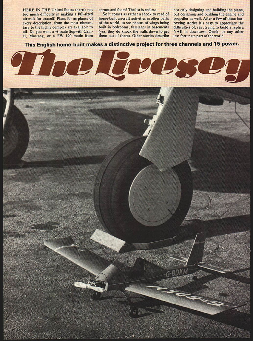
This English home-built makes a distinctive project for three channels and 15 power.
The Livesey D.L.5
The D.L.5 falls into the category of minimum aircraft, and makes use of as many non-aircraft parts as possible, wheels, tank, seat, etc., all being commercially available. Instead of costly aircraft plywood, marine ply is used wherever practical, and the engine is a converted Volkswagen. Extensive use is made of foam and fiberglass. Dimensions insure that all parts can go through a standard 30-in. wide door, so there's no need to knock down the house after building the project.
There are many more interesting and clever ideas in the D.L.5. All in all, it's a carefully thought out project to help the foreign home-builder achieve his goal a little sooner, a little cheaper, with a little less work. Bravo Mr. Livesey!
Our model is a stand-off scale version suitable for 1.5-size engines, and for three-channel radios.
Fuselage:
One of the things I was worried about was that the fuselage wouldn't be strong enough to stand very hard landing shocks, and would break about where the servos are installed, so I designed rather heavy fuselage sides.
The first step is to cut from good hard 1/8" sheet, four sides (F1), and two more from 1/32" ply. These are laminated together in a sandwich with the ply in the center. Glue these together to make the two basic side frames. Make sure they remain flat during the drying process. I put a flat board on top of the laminates, then weighted the board with a few heavy tools I had around the garage, and got some very flat sides when I removed the board. It's good to let this glue set overnight to make quite sure that the basic structure will be solid.
The next item is the top sheeting. This is made from four separate pieces, called out on the plans as F2, F3, and F4 (two required).
Cement these together to make the fuselage top, then cut out the aft fuselage sides (F5) and all the fuselage frames.
The fuselage is assembled upside down, so the first step is to sand the fuselage top to remove any glue spots, re-pin it to the building board, and then glue the forward and aft sides in place. Two stiffeners made from 3/8" triangle stock run the full length of the forward sides, and are glued in place, after which all the frames can be sanded to their final size and also glued in place.
A few more stiffeners made from this triangle stock are located around the 3/16" ply firewall, at the undercarriage location, and in the rear fuselage as additional gluing area for both the fin and the tailplane. A light sanding at this point and we'll be ready for stage two.
The pilot's backrest is next. Make the two frames F6 and F7, and glue them in place, together with the backbone strip of 1/4" x 1/4", and the two shoulder members made from 1/8" x 1/4". After this has dried the top 1/16" sheeting is attached. Since this is a highly curved member, select an oversized, pliable piece of 1/16" sheet, and soak it thoroughly in hot water. While wet, this sheet is gently curved over the structure, securely pinned in place but not glued. When dry, remove the pins and the sheet will remain curved. Trim to the final size, then glue into place. Simple flat pieces of 1/16" sheet make up the rest of the fairing. The addition of a small preshaped block of balsa aft of frame F7 completes this item.
The forward cockpit fairing is cut out from 1/8" sheet frame F16, and glued to the top of the fuselage, together with the 3/8" triangle reinforcing strip. Be sure that this strip is well attached, because it's all that prevents the battery from leading the model on a heavy landing! Build the battery box next from 1/8" sheet, contoured to suit your battery, then make and glue frame F15 in place. The access hole in this frame is tailored to suit your battery pack. A small sketch on the plan shows the shape of the battery box.
After all this is dry, sand the frame edges to their correct shape (a flat strip of wood covered with sandpaper is good for this). Attachment of the 1/32" ply fairing is the last step. To determine the shape of this fairing, make a thin card oversized fairing and pin it in place over the frames. Draw the correct shape on the card, cut it out, then transfer this shape to the ply. Cut out the ply slightly oversize, then epoxy it into place over the frames. When dry, sand gently to final configuration.
Wing:
The one-piece wing is composed of a flat center section and two dihedralled outer panels. Overall span is 48 in. You can save money by using 4-ft. wood lengths, especially for sheet items.
Basic structure is a D-sectioned torque box leading edge, with cap-stripped ribs, and a built-up trailing edge. The wing is bolted to the fuselage but, if you prefer, it can be held in place by rubberbands. Construction begins with the outer panels.
Start by slicing a 3-in. wide 4-ft. length of 1/16" sheet into a 1-in. and a 2-in. wide strips. Cut them to the correct length for the lower leading and trailing edges, then pin them on the plan covered with wax paper. With a soft pencil or a ballpoint pen make small marks to indicate the center of each rib. Cut out the lower cap strips from 3/16" sq. and cement them to the lower leading edge, then glue the lower 1/16" web sheeting in place. Keep the grain vertical and stop at the rib line.
The ribs, usually made from 1/16" sheet hard balsa, are cut from a template. Slice the rib sheet, pin them together on a block and sand to final shape. Be sure to make the ribs a little too long so they can be trimmed individually while being installed. Make enough ribs to complete the wing; seventeen special center section ribs are required. Glue ribs in place except the two innermost ones. Make sure each rib is located centrally; the lower cap strip and upper 3/16" sq. are glued in place followed by the 1/16" webbing. Clothespins make good clamps to hold sheet in place while gluing. Finish off the trailing edge by adding the upper piece of 1/16" sheet. After cutting to size, sand a small bevel on the aft end to provide a better gluing area and produce a pointed trailing edge. After wing completed, drill... After the wing is completed, drill the wing bolt holes and fit the 1/16" ply wing joiners into the back of the leading edge on both sides of the main spar. Assemble the two outer panels to the center section and cement in position; allow to dry.
Both fixed and movable tail surfaces are laminated from three pieces of sheet balsa with the centre ply having rectangular lightening holes. Cut to size and glue in place, lining up pencil marks. Use 3/16" sq. for the lower main spar and glue the lower leading edge sheeting in position. Make the ribs from 1/16" sheet hard balsa using the rib template: slice the rib sheet, pin the pieces together on a block and sand to final shape. Be sure to make the ribs a little too long so they can be trimmed individually when being installed.
Make enough ribs to complete the wing; seventeen special centre-section ribs are required. Glue the ribs in place except for the two innermost ones. Make sure each rib is located centrally; glue the lower cap strip and the upper 3/16" sq. in position followed by the 1/16" sheet webbing. Note that the grain of the web sheeting should be vertical; it is glued to the forward side of the main spars. Clothespins make good clamps to hold the sheeting while gluing.
Finish off the trailing edge by adding the upper piece of 1/16" sheet. After cutting to size, sand a small bevel on the aft end to provide a better gluing area and form a pointed trailing edge. The wing centre section is a separate item: build the bridging piece between the two outer panels. First trim the inboard ends of the spars of the wing panels to the correct lengths and angles — the small sketch on the plans shows the correct angle template. Pin the two panels to the plan separated by the width of the centre section and prop up to the required dihedral angle. Make quite sure the wing panels are correctly positioned; you do not want to build wing warps.
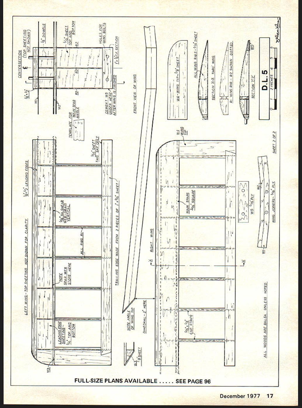
Build the centre section by joining the various spars in the following order. First cement and place the 1/16" lower leading edge sheet and the 1 x 1/4" solid trailing edge piece — the latter should be a strong piece of wood to seat the wing bolts. Glue the lower main spar and leading edge onto the leading edge sheet and install the upper 3/16" sq. spar. Allow to dry. Make and fit the 1/16" ply wing joiners to the back of the leading edge on both sides of the main spar, then secure the wing to the fuselage with the wing bolts. LEFT WING - TOP SHEETING NOT SHOWN FOR CLARITY
TRAILING EDGE MADE FROM 2 PIECES OF 1 x 6 SHEET
FRONT VIEW OF WING
1/16" WING TIP - 1/4" SHEET
ALL WING RIBS 5/16" SHEET
MAIN SPARS 3/16" SQUARE
WING JOINERS 1/16" PLY SHEET
R1 WING RIB - R2 SHOWN DOTTED
SECTION A-A
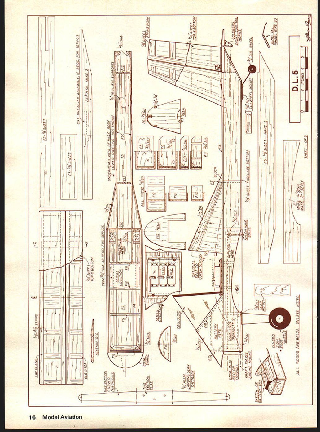
ALL WOODS ARE BALSA UNLESS NOTED
D.L.5
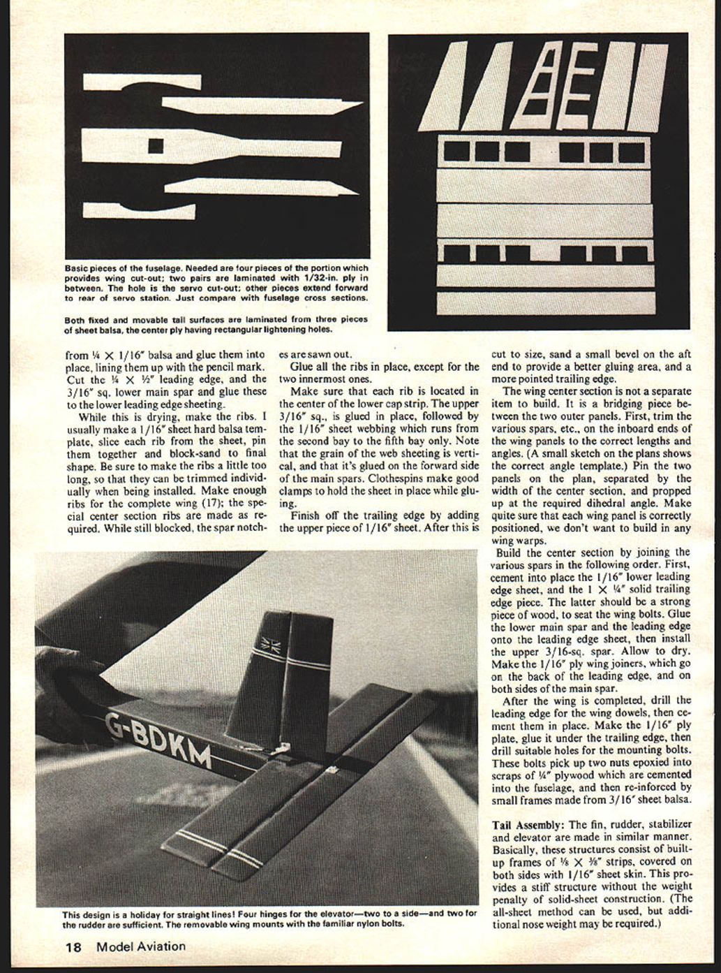
FULL-SIZE PLANS AVAILABLE ..... SEE PAGE 96 Basic pieces of the fuselage. Needed are four pieces of the portion which provides wing cut-out; two pairs are laminated with 1/32-in. ply in between. The hole is the servo cut-out; other pieces extend forward to rear of servo station. Just compare with fuselage cross sections.
Both fixed and movable tail surfaces are laminated from three pieces of sheet balsa, the center ply having rectangular lightening holes.
from 1/4 x 1/16" balsa and glue them into place, lining them up with the pencil mark.
Cut the 1/4 x 1/2" leading edge, and the 3/16" sq. lower main spar and glue these to the lower leading edge sheeting.
While this is drying, make the ribs. I usually make a 1/16" sheet hard balsa template, slice each rib from the sheet, pin them together and block-sand to final shape. Be sure to make the ribs a little too long, so that they can be trimmed individually when being installed. Make enough ribs for the complete wing (17); the special center section ribs are made as required. While still blocked, the spar notches are sawn out.
Glue all the ribs in place, except for the two innermost ones.
Make sure that each rib is located in the center of the lower cap strip. The upper 3/16" sq. is glued in place, followed by the 1/16" sheet webbing which runs from the second bay to the fifth bay only. Note that the grain of the web sheeting is vertical, and that it's glued on the forward side of the main spars. Clothespins make good clamps to hold the sheet in place while gluing.
Finish off the trailing edge by adding the upper piece of 1/16" sheet. After this is cut to size, sand a small bevel on the aft end to provide a better gluing area, and a more pointed trailing edge.
The wing center section is not a separate item to build. It is a bridging piece between the two outer panels. First, trim the various spars, etc., on the inboard ends of the wing panels to the correct lengths and angles. (A small sketch on the plans shows the correct angle template.) Pin the two panels on the plan, separated by the width of the center section, and propped up at the required dihedral angle. Make quite sure that each wing panel is correctly positioned, we don't want to build in any wing warps.
Build the center section by joining the various spars in the following order. First, cement into place the 1/16" lower leading edge sheet, and the 1 x 1/4" solid trailing edge piece. The latter should be a strong piece of wood, to seat the wing bolts. Glue the lower main spar and the leading edge onto the leading edge sheet, then install the upper 3/16" sq. spar. Allow to dry.
After the wing is completed, drill the leading edge for the wing dowels, then cement them in place. Make the 1/16" ply plate, glue it under the trailing edge, then drill suitable holes for the mounting bolts. These bolts pick up two nuts epoxied into scraps of 1/4" plywood which are cemented into the fuselage, and then re-inforced by small frames made from 3/16" sheet balsa.
Tail Assembly
The fin, rudder, stabilizer and elevator are made in similar manner. Basically, these structures consist of built-up frames of 1/8 x 3/8" strips, covered on both sides with 1/16" sheet skin. This provides a stiff structure without the weight penalty of solid-sheet construction. (The all-sheet method can be used, but additional nose weight may be required.) Begin by stripping 36-in. lengths of 1/8 x 3/8" balsa, cutting them to length for the leading and trailing edge pieces. Pin these to the plan, then cut and glue in place the crosspieces, which are also cut from 1/8 x 3/8". A wider piece of 1/8" sheet is required at the centersection. Make the fin and rudder frameworks in a similar way.
When the glue is dry, lift these surfaces carefully from the plans; the rudder and elevator are especially fragile at this stage. Cut out the four pieces of 1/16" sheet for each of the upper and lower skins. Glue one set of these skins onto one side of the four frames. When dry, gently sand the tailplane and fin flat, then glue into place the other skin pieces.
The elevator and rudder need more preparation before attaching the remaining sheeting. The aim here is to present a scale appearance to the controls, so sand away the ribs to a point at the trailing edge, also slightly bevelling the trailing edge sheet. The plans show typical cross sections. Test the upper surface sheet for a good fit before finally gluing it into place.
Sand all controls to the final contours shown on the plans.
Radio Installation
I will not give an involved discussion of how to install my radio in your model. The odds are that your radio will be different from mine, with different space requirements. So I suggest that you lay your radio components over the plans to see what, if any, modifications you'll need to make.
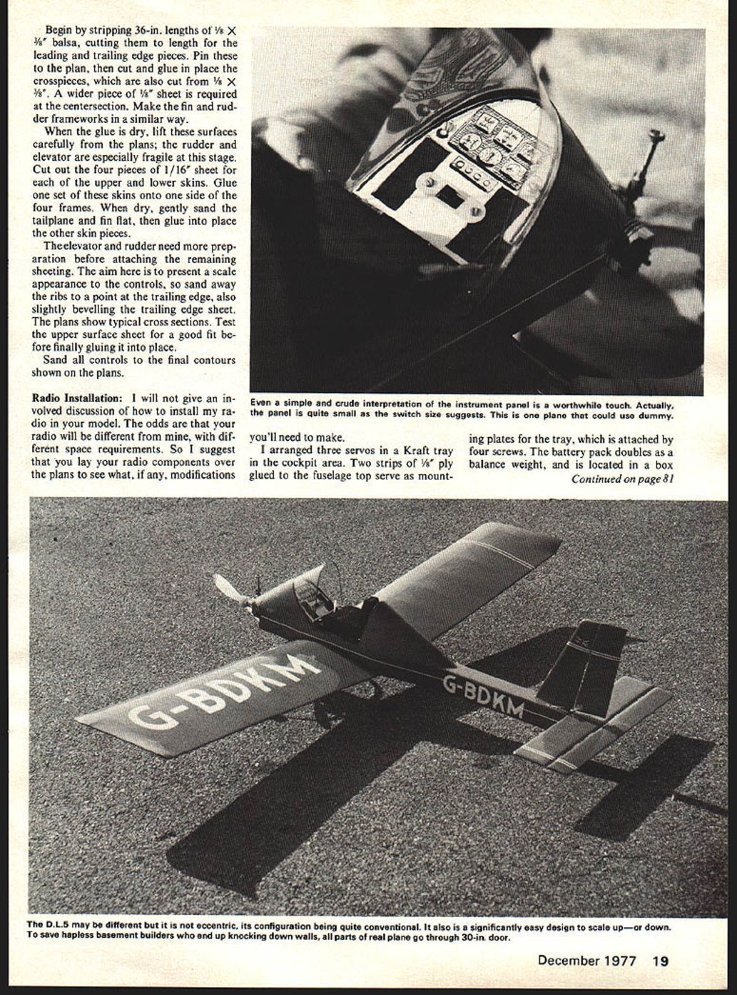
I arranged three servos in a Kraft tray in the cockpit area. Two strips of 1/8" ply glued to the fuselage top serve as mounting plates for the tray, which is attached by four screws. The battery pack doubles as a balance weight, and is located in a box. The receiver is built inside the forward cockpit structure. The battery is prevented from falling out by the dummy instrument panel. The receiver sits in the center cavity between the wing bolts, and all the wiring can be run in the space above the wing.
Control hook-ups on the prototype were made with Nyrods (elevator and rudder), and with cable to the engine. Be sure to run all these before fitting the bottom sheeting to the fuselage.
Covering:
Our prototype was covered with orange Solarfilm, then trimmed with white stripes and registration letters. The only point where you have to be careful is the reflexed section at the wing tips. Here, make sure that the covering is attached securely to the last wing rib before ironing it to the tip plate.
As far as we've been able to determine the actual D.L.5 has yet to be completed, so there's no "factory finish" to be copied. Don't be shy about using any color scheme you fancy! Glue the celluloid wind screen in place.
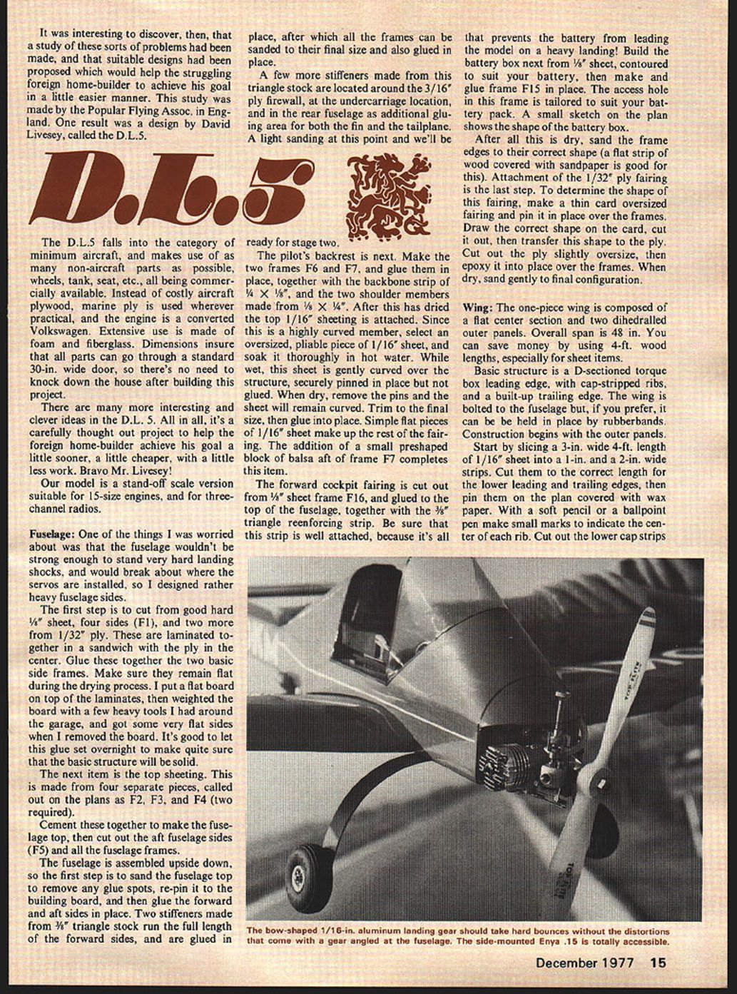
Undercarriage:
The main gear support is made from a strip of 1/16" sheet aluminum, cut to the profile shown on the plans. Bend as indicated. The curved appearance simulates the full-size aircraft. The curve is a constant-radius arc of laminated ash bonded with fiberglass.
For the tailwheel, bend a scrap of 1/16" piano wire, then attach it to the body with a couple of small screws.
Cockpit Detail:
As much detail as desired (or none at all) can be added, but the dummy instrument panel is necessary to keep the battery in place, and to provide a convenient place for the ON/OFF switch. Make the panel from 1/16" ply, to the same shape as frame F15 but about 1/8" smaller all round and without the cut-out for the battery. Hold the panel in place with a couple of small screws, which go into a couple of scrap pieces of 1/16" ply cemented to F15.
A dummy seat is a useful item, because it protects the servos from the dust and dirt blowing around the flying site (see photos for the seat we used). Add the control stick and other desired details.
Flying:
Pre-flight check is essential before going out to the strip. Check the servo action, making sure that left is left, up isn't down, and that the engine controls are "easy." Check the C.G. location, which should be within 1/4" of the location on the plan, and ballast the model as necessary.
Transcribed from original scans by AI. Minor OCR errors may remain.

