
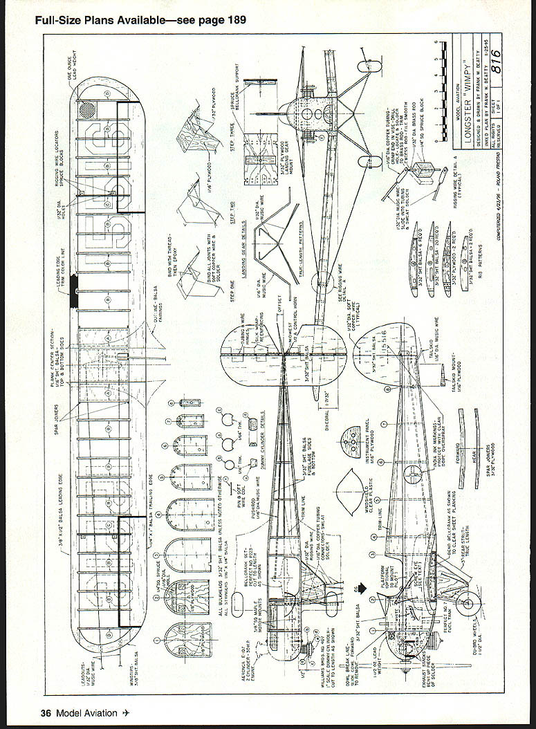
Longster Wimpy
Frank Beatty
The Longster Wimpy: Amateur aircraft builders of the late '20s and early '30s faced many difficulties. Among these were the lack of light, cheap, reliable engines, a dearth of technical design engineering data, and restrictive (or outright prohibitive) government policies.
Despite this, Leslie Long and his brother (co‑proprietors of a radio factory in Oregon) designed, built, and flew at least nine different home‑built aircraft over a ten‑year period. The most successful and best known of these was the Longster Wimpy.
The Wimpy appeared in 1935. Its original powerplant, a Harlequin, was soon replaced with the newly developed Aeronca E‑107 aircraft engine.
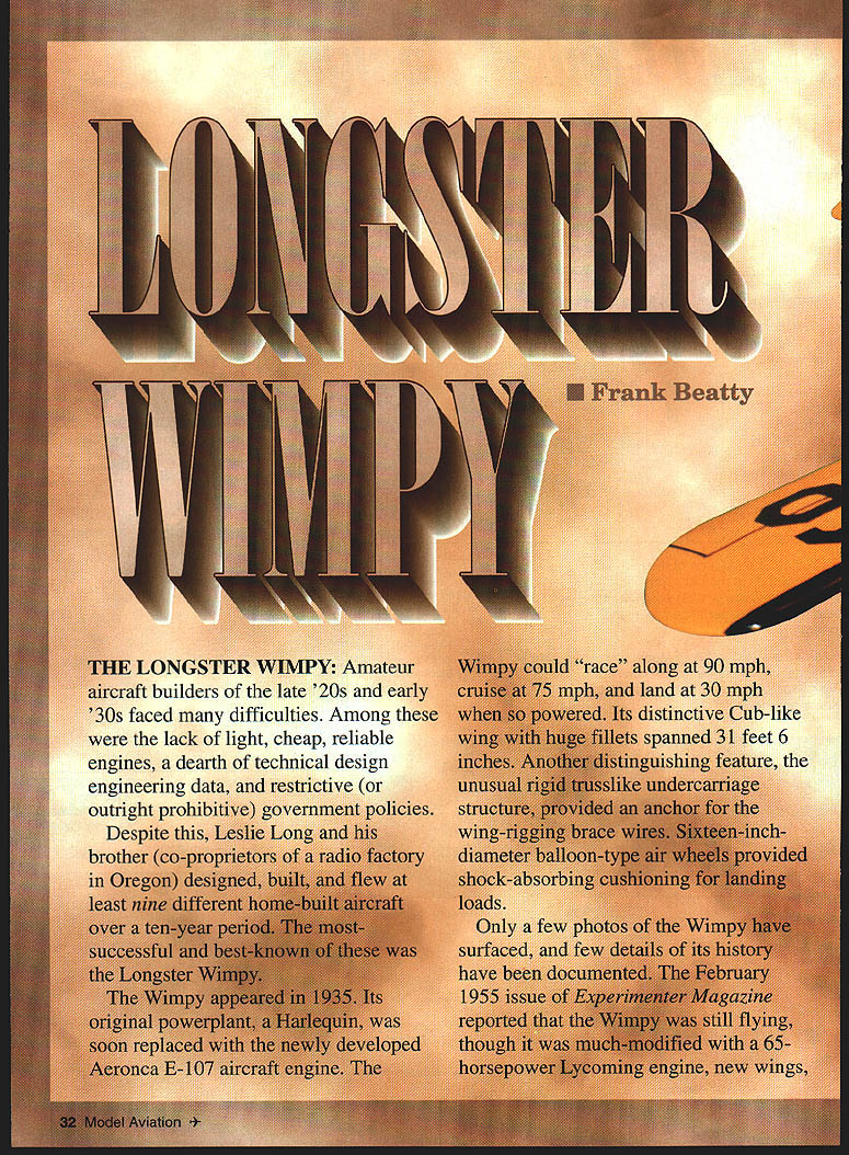
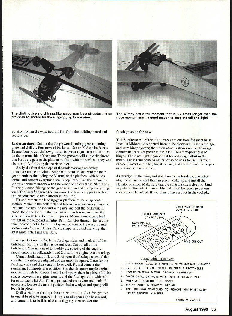
The Wimpy could "race" along at 90 mph, cruise at 75 mph, and land at 30 mph when so powered. Its distinctive Cub‑like wing with huge fillets spanned 31 feet 6 inches. Another distinguishing feature, the unusual rigid truss‑like undercarriage structure, provided an anchor for the wing‑rigging brace wires. Sixteen‑inch‑diameter balloon‑type air wheels provided shock‑absorbing cushioning for landing loads.
Only a few photos of the Wimpy have surfaced, and few details of its history have been documented. The February 1955 issue of Experimenter Magazine reported that the Wimpy was still flying, though it was much modified with a 65‑horsepower Lycoming engine, new wings, and a revamped turtledeck.
A three‑view and photo of the Wimpy came from the Winter 1969 issue of Air Progress–Sport Aircraft; drawings of an early Aeronca aircraft engine came from EAA Aircraft Engines Volume 1. These were the references used for the construction drawings, detailing, and markings of the model. A Free Flight model construction article by Walt Mooney from the September 1954 issue of Model Airplane News and an Electric RC construction article by Le Gray in the March 1980 Model Builder were also useful reference sources.
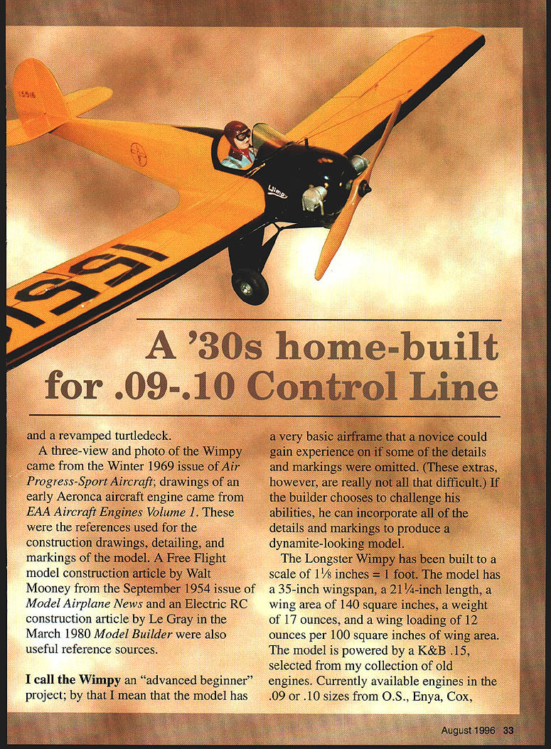
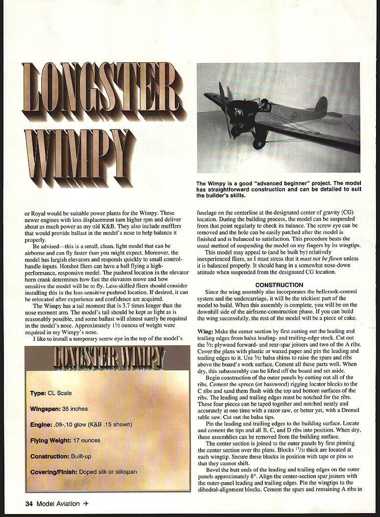
I call the Wimpy an "advanced beginner" project; by that I mean the model has a very basic airframe that a novice could gain experience on if some of the details and markings were omitted. These extras, however, are not really that difficult. If the builder chooses to challenge his abilities, he can incorporate all of the details and markings to produce a dynamite‑looking model.
Specifications
- Type: CL Scale
- Wingspan: 35 inches
- Engine: .09–.10 glow (K&B .15 shown)
- Flying weight: 17 ounces
- Construction: Built‑up
- Covering/finish: Doped silk or silkspan
The Longster Wimpy model has been built to a scale of 1 1/8 inches = 1 foot. The model has a 35‑inch wingspan, a 21 1/4‑inch length, a wing area of 140 square inches, a weight of 17 ounces, and a wing loading of 12 ounces per 100 square inches of wing area. The model is powered by a K&B .15, selected from my collection of old engines. Currently available engines in the .09 or .10 sizes from O.S., Enya, Cox, or Royal would be suitable powerplants for the Wimpy. These newer engines with less displacement turn higher rpm and deliver about as much power as my old K&B. They also include mufflers that provide ballast in the model's nose to help balance it properly.
Be advised—this is a small, clean, light model that can be airborne and can fly faster than you might expect. Moreover, the model has largish elevators and responds quickly to small control‑handle inputs. Hotshot fliers can have a ball flying a high‑performance, responsive model. The pushrod location in the elevator horn crank determines how fast the elevators move and how sensitive the model will be to fly. Less‑skilled fliers should consider installing the less‑sensitive pushrod location. If desired, it can be relocated after experience and confidence are acquired.
The Wimpy has a tail moment that is 3.7 times longer than the nose moment arm. The model's tail should be kept as light as is reasonably possible, and some ballast will almost surely be required in the model's nose. Approximately 1½ ounces of weight were required in my Wimpy's nose.
I like to install a temporary screw eye in the top of the fuselage on the centerline at the designated center‑of‑gravity (CG) location. During the building process, the model can be suspended from that point regularly to check its balance. The screw eye can be removed and the hole easily patched after the model is finished and balanced to satisfaction. This procedure beats the usual method of suspending the model on my fingers by its wingtips.
This model may appeal to (and be built by) relatively inexperienced fliers, so I must stress that it must not be flown unless it is balanced properly. It should hang in a somewhat nose‑down attitude when suspended from the designated CG location.
CONSTRUCTION
Since the wing assembly also incorporates the bellcrank‑control system and the undercarriage, it will be the trickiest part of the model to build. When this assembly is complete, you will be on the downhill side of the airframe‑construction phase. If you can build the wing successfully, the rest of the model will be a piece of cake.
Wing
Make the center section by first cutting out the leading and trailing edges from balsa leading‑ and trailing‑edge stock. Cut out the 3/32‑inch plywood forward‑ and rear‑spar joiners and two of the A ribs. Cover the plans with plastic or waxed paper and pin the leading and trailing edges to it. Use 3/32‑inch balsa shims to raise the spars and ribs above the board's work surface. Cement all these parts well. When dry, this subassembly can be lifted off the board and set aside.
Begin construction of the outer panels by cutting out all of the ribs. Cement the spruce (or basswood) rigging locator blocks to the C ribs and sand them flush with the top and bottom surfaces of the ribs. The leading and trailing edges must be notched for the ribs. These four pieces can be taped together and notched neatly and accurately at one time with a razor saw, or better yet, with a Dremel table saw. Cut out the balsa tips.
Pin the leading and trailing edges to the building surface. Locate and cement the tips and all B, C, and D ribs into position. When dry, these assemblies can be removed from the building surface.
The center section is joined to the outer panels by first pinning the center section over the plans. Blocks 17/32‑inch thick are located at each wingtip. Secure these blocks in position with tape or pins so that they cannot shift.
Bevel the butt ends of the leading and trailing edges on the outer panels approximately 8°. Align the center‑section spar joiners with the outer‑panel leading and trailing edges. Pin the wingtips to the dihedral‑alignment blocks. Cement the spars and remaining A ribs in position. When the wing is dry, lift it from the building board and set it aside.
Undercarriage
Cut out the 3/32‑inch plywood landing‑gear mounting plate and drill the four rows of 1/16‑inch holes. Use an X‑Acto knife or a Dremel burr to cut shallow grooves between adjacent pairs of holes on the bottom side of the plate. These grooves will allow the thread that binds the gear to the plate to be flush with the surface. They will also simplify finishing the surface later.
Study the first three steps of the undercarriage assembly procedure on the drawings:
- Bend up and bind the main gear members (including the V strut) to the platform with button thread and cement everything well.
- Bind the remaining 1/32‑inch music wire members with fine wire and solder them.
- Fit the plywood fairings to the gear as shown and epoxy everything well. The 3/16 x 1/2‑inch spruce (or basswood) bellcrank support and bolt can be cemented to the platform at this time.
Fit and cement the landing‑gear platform to the wing center section. Make up the bellcrank and leadout wire assembly. Pass the leadouts through the inboard wing ribs and bolt the bellcrank in place. Bend the loops in the leadout wire ends now, or cover the sharp ends with tape to prevent injuries. Mount a one‑ounce lead weight on the outboard wingtip. Drill 1/32‑inch holes through the rigging‑wire locator blocks. Cover the top and bottom of the wing's center section with 1/16‑inch sheet balsa. Carve, shape, and sand the wing, then set it aside until final assembly.
Fuselage
Cut out the 3/32‑inch balsa fuselage sides and mark all bulkhead locations on the inside surfaces. Cut out all the bulkheads. You may need to modify the spacing of the engine‑mount cutouts in bulkheads 1 and 2 to suit the engine you are using. Cement bulkheads 1, 2, and 3 between the fuselage sides. Make sure that the sides are aligned and the assembly is square. Chamfer the fuselage ends and then cement the fuselage sides together. Cement the remaining bulkheads into position. Slip the 3/8‑inch square maple engine mounts through bulkheads 1 and 2 and epoxy them in place. (Fill the spaces between the engine mounts and the fuselage sides with balsa for extra strength.) Add filler‑pipe extensions to your fuel tank, if necessary. Locate the tank's position; balsa wedges and epoxy will lock it in place.
Drill a 1/16‑inch hole through the center, or cut a 1/16 x 1/16‑inch groove in one side of a 1/4 x 1 3/4‑inch piece of spruce (or basswood) and cement it to bulkhead 2 as a rigging locator. Set the fuselage aside for now.
Tail Surfaces
All tail surfaces are cut from 3/32‑inch sheet balsa. Install a Midwest 1/2‑A control horn in the elevators. I used a tubing‑and‑wire hinge system; that installation is shown on the drawings. Some readers might prefer to use Klett RK‑4 flex‑point plastic hinges. These are lighter (important for reducing ballast in the model's nose) and perhaps easier for some to use. It's your choice. Cover the rudder, fin, stabilizer, and elevators with silkspan or silk and set them aside.
Assembly
Fit the wing and stabilizer to the fuselage, check for alignment, and cement them in place. Make up and install the elevator pushrod. Make sure that the control system does not bind anywhere. The tail‑skid assembly and all fuselage bottom sheeting can be added.
If you plan to have a pilot in the cockpit, full‑size plans are available—see page 189. Install the mounting platform now. Add the fuselage top sheeting and stringers. The fuselage wing fairings are made up of a combination of sheet balsa, balsa blocks, and Hobbico Hobbylite Filler. Cement the fin in place.
Cowling: The cowling is a combination of sheet balsa sides and balsa blocks. The pieces are shaped and hollowed out to suit the engine and its needle‑valve and exhaust cutouts. Two 1/2‑inch‑long wood screws work as the cowling hold‑downs.
Finishing: Fill all of the dings and pinholes with Hobbico Filler. Sand the model smooth and brush on two to four coats of clear dope. Sand it smooth, and cover the entire model with silkspan or silk (I always use silk). Brush on six coats of clear dope. Spray on six coats of thinned‑out balsa filler‑coat primer. Spray on four to eight coats of yellow dope. Throughout this procedure wet‑sand the model with 400‑ or 600‑grit wet‑or‑dry sandpaper after every two or three coats. The last coat is hand‑rubbed using a soft diaper (or an undershirt) and No. 7 Heavy‑Duty Rubbing Compound. Now you can apply the trim and markings.
Trim: Whenever possible, I cut stencils and spray the registration numbers on my models. Use light cardboard similar to 4 x 6‑inch index‑card material. Trace the number outlines, and use a straightedge and an X‑Acto knife to cut the outline. Remember to save the center of the number 6 cut‑out. Leave a 1/4‑inch‑wide border around all sides of this group of numbers, then cut out approximately 1/4 x 3/8‑inch rectangles. These will be strategically located between the numbers and at other key spots.
Tape around the four sides of the stencil to hold it onto the model's wing, then use bits of tape over each of the 1/8 x 3/8‑inch cutouts to hold the stencil in the desired location. The tape should be Scotch 3M No. 320 Drafting Tape; it leaves a minimum of residue and doesn't lift previous coats of paint when removed. Mask off the rest of the wing and fuselage to prevent any overspray on the numbers.
I spray light (nearly dry) dusting coats of paint at right angles to the surface and the stenciled areas. I don't worry if the stencil flutters up and down a bit; that ensures the wet paint won't bond the stencil to the painted surfaces. There will probably be some overspray or fuzzy edges; judicious use of rubbing compound will remove the unwanted paint and leave crisply outlined numbers. Four coats of black should be about right. Remove all masking tape and rub the entire model down with No. 7 White Polishing Compound.
The "Long" fuselage logo and the rudder registration numbers were put on with a technical pen, draftsman's templates, and black India ink. A Berol R‑40 circle template, a Berol R‑960 Vernal Lettering Guide, and an Alvin Reform Reprograph No. 2 technical pen were used. The India ink markings will smudge unless protected with a clear dope overspray.
The white "Wimpy" was hand‑painted with thinned white dope and a 6/0 Bettsbyrd Aqua‑Sable Liner 400 brush. An alternate method would be to use a Pentel White 100WS marker.
The elevator outlines were made from 1/16‑inch‑wide strips of dope that were lifted from a soaped glass panel that had been sprayed with black dope. (For more information on this technique, see the Hot Canary article in the March 1996 Model Aviation.)
Rigging Wires
Pass lengths of 1/32‑inch brass wire through the fuselage and wing rigging‑wire locator blocks. Then fabricate 1/16‑inch‑diameter copper (or brass) tubing fittings, as shown in Detail A on the drawings. Use a small punch to mark the drilling points on the fittings so the 1/32‑inch drill bit will not wander when you drill these holes.
Align and fit the components of the upper sets of bracing wires and tubing fittings; solder these only at the wing‑panel locators. Turn the model over, align everything, and fit the wires and fittings. Solder the parts together, again only at the wing‑panel locators.
Obtain two kitchen chairs, preferably with padded seats, and space them about 26 inches apart. Place the model between the chairs, resting on its wingtips. Have an assistant press down lightly on the model, and sweat‑solder the wire and tubing fittings near the fuselage. Turn the model on its back and repeat the procedure. Nothing looks more unsightly than rigging wires that sag or flex. Yours, however, should be quite taut and can be accomplished easily.
Final Details
The dummy engine cylinders were made from cut‑down Williams Bros. cylinders (No. 407) and various odd pieces. I filled the cylinders with lead, and the dummy exhaust stacks were made from solder to add a little ballast.
Now fit the cylinders, windshield, instrument panel, rudder, and wheels to the model. Bolt the engine, propeller, and cowling to the model. Suspend the completed model from the screw eye. If it does not hang in a slightly nose‑down attitude, it's tail heavy and will be an unstable flier. If the model is tail heavy, gouge out the cowling with a Dremel burr and add lead weight in the cavity until proper balance is achieved. If your engine has a muffler fitted to it, this extra ballast may be unnecessary.
Flying
You have created a small, clean, light airplane that will fly fast and respond quickly to control‑handle inputs. The largish wheels are open, widely spaced, and well forward of the model's CG, so landings should be a piece of cake. Proper flying‑wire lengths and diameters will depend on the engine you install. Have a more experienced flier or a hobby‑shop proprietor advise you about this.
If you have followed all the steps described in this article, you will have been exposed to and will have tackled techniques that took me decades to master. Best of all, these techniques can be applied to every model you build in the future.
Now, don't you feel good?
Frank W. Beatty 2608 Pontoon Rd. Granite City, IL 62040
Transcribed from original scans by AI. Minor OCR errors may remain.

