
Louver Punch
Editor's note
Our English author is a frequent contributor to that country's RCM&E. Certain British terms and phrases have been retained — with explanations where necessary — to capture the "flavour" of Mr. Kent's writing.
The problem
While building the Alexander Bullet (November 1995 Model Aviation) I chose to model the version with fixed undercarriage. No problems there, but the cowl panels behind the five-cylinder Wright Whirlwind engine were covered in louvers (exits for cooling air). Reproducing those louvers on the model was the tricky part.
Making and fitting each louver individually would have been time-consuming, so I decided the only practical way was to punch the louvers out of litho plate, as would be done for full-size panels.
Materials
- 1 in. diameter aluminium bar (for the punch)
- Angled aluminium stock (for the die/blanking plate)
- Plywood base
- Perspex (acrylic) guide, slotted for adjustment
- Litho plate (panel material)
- Drill press (used as a fly press)
- 6 mm drill (used to lock the chuck)
- Strong rubber band
- Files, emery cloth
- Saw
- Evostick adhesive
Making the punch and die
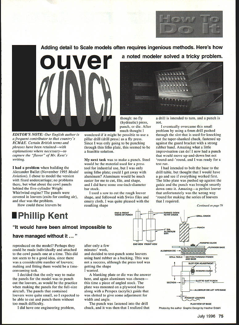
I had no fly (hydraulic) press, punch, or die, so I investigated using a pillar drill (drill press) as a fly press. Since I was only punching thin litho plate this seemed feasible.
I made the punch from aluminium bar because it was easier to cut, file and shape than steel. After sawing the rough shape I refined it with Swiss files and emery cloth.
For a backing I first tried hard rubber, but the results were unsatisfactory. A blanking plate (die) was needed. I made the die from angled aluminium stock and mounted it on a plywood base. A Perspex guide was slotted into the base to allow adjustment of width and angle.
Adapting the drill press
With the punch in the drill chuck I realised a drill is intended to turn, not to act as a non-rotating punch. To prevent rotation I pushed a 6 mm drill through the slot used for knocking out a taper-shank chuck and fastened it up against the guard bracket with a strong rubber band. This held the chuck steady so the punch could move up and down without rotating.
Trial and refinement
My first test produced a perfectly formed louver but oriented the wrong way for the series I needed. I removed the die, reshaped the punch as a simple rectangle, turned the punch through 180° and tried again. Success: a series of nine punched louvers on 12 mm centres with only minor tearing at the corners.
I reduced corner tearing by giving both punch and die softer curves and by breaking the die edge with a small radius rather than a sharp edge. The die's rear sides helped hold the litho plate in place. After bolting the base to the drill table, production proceeded quickly.
Some louvers on the Bullet cowl sit at more than 90°. For those panels I set the guide to the required angle and punched them in the same way. All panels were produced in a short time and fitted well to the nose sections of the model.
Forming and fitting the panels
Because the cowl has some curvature, I experimented with bending the punched panels. It proved easy to bend each panel around a piece of aluminium bar without damaging the louvers.
The panels were attached to the nose section with Evostick adhesive. Follow the manufacturer's instructions for drying/tackiness: allowing the adhesive to reach the recommended tacky state before final fitting gives the opportunity to slide the panel into the correct position before the bond sets.
Conclusion
I was very pleased with the performance of this simple punch and die. The improvised drill-press setup and aluminium tooling made rapid, accurate production of louvered panels possible — a tool I would have found almost impossible to manage without on this model.
Phillip Kent
Transcribed from original scans by AI. Minor OCR errors may remain.

