
Low-voltage Detector/Indicators
FOR MANY YEARS, the modern RC system traditionally has had a meter that indicated RF output by bleeding off a tiny bit of the RF from the final amplifier, rectifying it via a diode and using the rectified output to drive a sensitive micro or milli-meter. Most have afforded a rough indication of RF output and one could really only use as an indication if there were a significant change, e.g., "50 percent or normal."
One simply estimated safe flying time for airborne battery pack, e.g., six 15-minute flights. Eventually, some improvement was afforded with the introduction of battery test units such as the Super Cycle and several others that discharge the pack through a calibrated load and indicate the discharge time. At least this provides one with a better estimate of capacity and helps spot bad cells.
However, something better was needed and individual modelers tackled the problem. One of the first that I recall was Sid Kaufman who sent me a schematic for a device he called the "Mitter-Minder" about six years ago and I presented it in my A.M. column.
Others have continued to develop better ways. The Power-CYT is a transistor device with a sensitive set point. A simple Light Emitting Diode (LED) can be used if rigged properly. However, all have their strengths and weaknesses; temperature drift, the hysteresis between On and Off may be too broad, current drain is too high, LED's are hard to see in direct sunlight, etc. This article will attempt to discuss several ways of obtaining good, useable Low Voltage Detection (LVD) and Indication (LVI) and will permit the reader to select the approach that suits his needs best. Devices are presented for both transmitter and receiver packs.
I've always been concerned about flying systems that use dry batteries and that have no indicator. It's a pain to have to use a volt-meter to check after each flight and you never really know when a dry battery will die. My earliest attempts to develop a simple device were built around an LED in series with a Zener diode. This works but has a rather broad hysteresis, i.e., it will go off at, say, 8 volts but won't come back on until voltage increases to perhaps 10 volts.
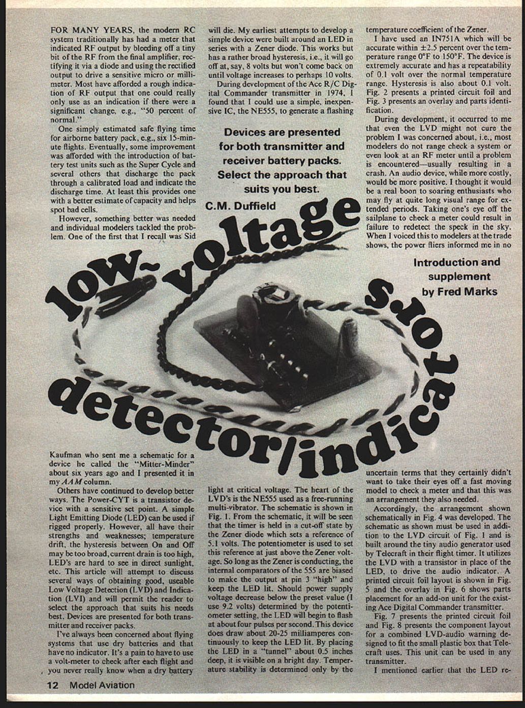
During development of the Ace R/C Digital Commander transmitter in 1974, I found that I could use a simple, inexpensive IC, the NE555, to generate a flashing
Devices are presented for both transmitter and receiver battery packs. Select the approach that suits you best.
C.M. Duffield
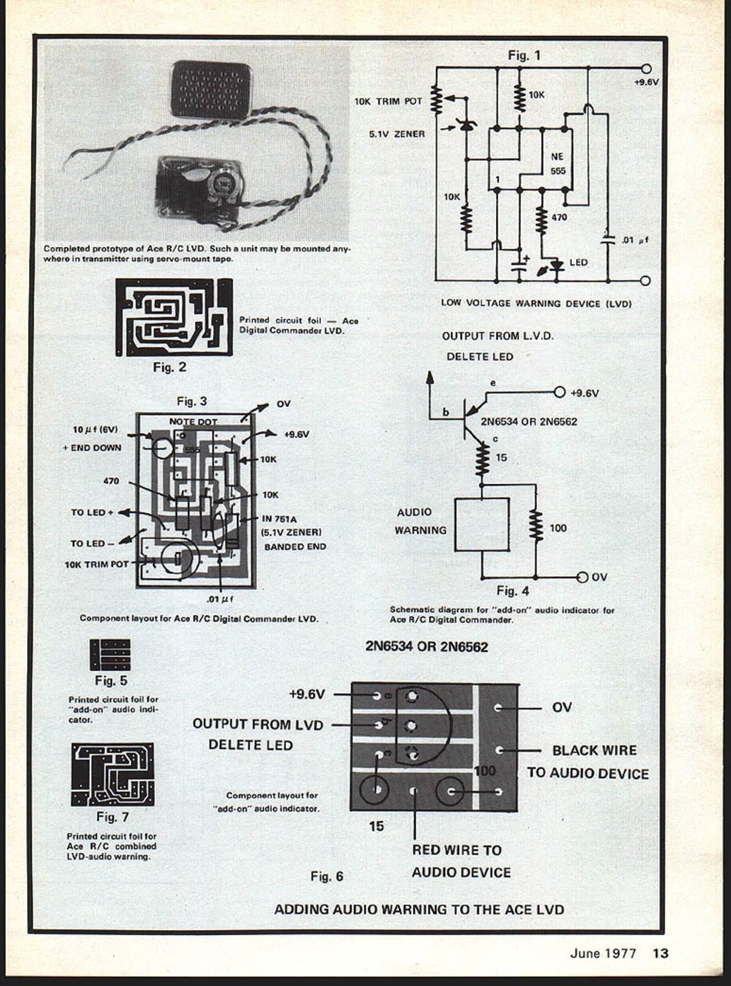
temperature coefficient of the Zener. I have used an IN751A which will be accurate within ±2.5 percent over the temperature range of 0° to 150°F. The device is extremely accurate and has a repeatability of 0.1 volt over the normal temperature range. Hysteresis is also about 0.1 volt. Fig. 2 presents a printed circuit foil and Fig. 3 presents an overlay and parts identification.
During development, it occurred to me that even the LVD might not cure the problem I was concerned about, i.e., most modelers do not range check a system or even look at an RF meter until a problem is encountered—usually resulting in a crash. An audio device, while more costly, would be more positive. I thought it would be a real boon to soaring enthusiasts who may fly at quite long visual range for extended periods. Taking one's eye off the sailplane to check a meter could result in failure to detect the speck in the sky. When I voiced this to modelers at the trade shows, the power fliers informed me in no uncertain terms that they certainly didn't want to take their eyes off a fast moving model to check a meter and that this was an arrangement they also needed.
Accordingly, the arrangement shown schematically in Fig. 4 was developed. The schematic as shown must be used in addition to the LVD circuit of Fig. 1 and is built around the tiny audio generator used by Telecraft in their flight timer. It utilizes the LVD with a transistor in place of the LED, to drive the audio indicator. A printed circuit foil layout is shown in Fig. 5 and the overlay in Fig. 6 shows parts placement for an add-on unit for the existing Ace Digital Commander transmitter.
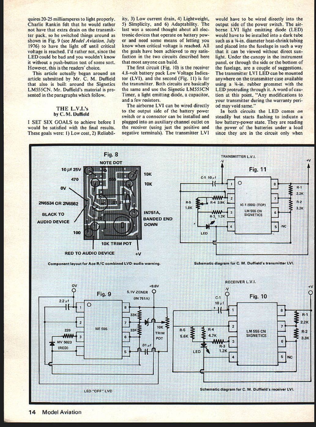
Fig. 7 presents the printed circuit foil and Fig. 8 presents the component layout for a combined LVD-audio warning designed to fit the small plastic box that Telecraft uses. This unit can be used in any transmitter.
I mentioned earlier that the LED re
ADDING AUDIO WARNING TO THE ACE LVD
requires 20-25 milliamperes to light properly. Charlie Rankin felt that he would rather not have that extra drain on the transmitter pack, so he switched things around as shown in Fig. 9 (see Model Aviation, July 1976) to have the light off until critical voltage is reached. I'd rather not, since the LED could be bad and you wouldn't know it without a push-button test of some sort. However, this is the readers' choice.
This article actually began around an article submitted by Mr. C. M. Duffield that also is built around the Signetics LM555CN. Mr. Duffield's material is presented in the paragraphs which follow.
THE L.V.I.'s
by C. M. Duffield
I SET SIX GOALS to achieve before I would be satisfied with the final results. These goals were: 1) Low cost, 2) Reliability, 3) Low current drain, 4) Lightweight, 5) Simplicity, and 6) Adaptability. The last was a second thought about all electronic devices that operate on battery power and need some means of letting you know when critical voltage is reached. All the goals have been achieved to my satisfaction in the two circuits described here that most anyone can build.
The first circuit (Fig. 10) is the receiver 4.8-volt battery pack Low Voltage Indicator (LVI), and the second (Fig. 11) is for the transmitter. Both circuits are basically the same and use the Signetics LM555CN Timer, a light emitting diode, a capacitor, and a few resistors.
The airborne LVI can be wired directly to the output side of the battery power switch or a connector can be installed and plugged into an auxiliary channel outlet on the receiver (using just the positive and negative terminals). The transmitter LVI would have to be wired directly into the output side of the power switch. The airborne LVI light emitting diode (LED) would have to be installed into a dark tube such as a 1/4-in. diameter heat-shrink tubing and placed into the fuselage in such a way that it can be viewed without direct sunlight. Under the canopy in the instrument panel, or through the side or the bottom of the fuselage, are a couple of suggestions. The transmitter LVI LED can be mounted anywhere on the transmitter case available using a 1/4-in. rubber grommet with the LED protruding through it. A word of caution at this point, "Any modifications to your transmitter during the warranty period may void same."
In both circuits the LED comes on steadily but starts flashing to indicate a low battery-power state. They are reading the power of the batteries under a load since they are in the circuit only when power is applied.
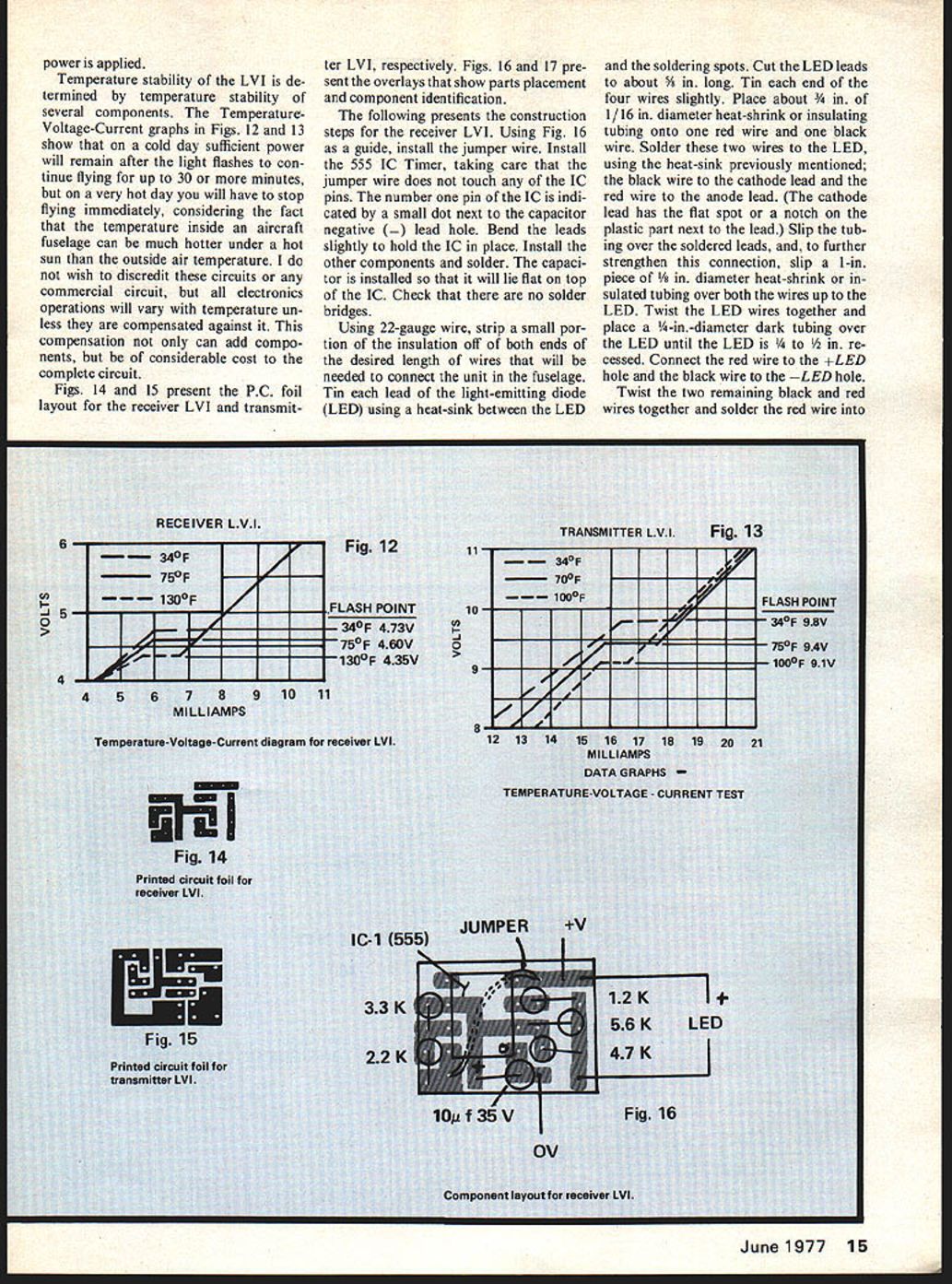
Temperature stability of the LVI is determined by several components. Temperature-Voltage-Current graphs (Figs. 12-13) show that on a cold day sufficient power will remain after the light first starts flashing to continue flying up to 30 minutes. On a very hot day you will have to stop flying immediately, considering the fact that the temperature inside the aircraft fuselage can be much hotter than the outside air temperature. I do not wish to discredit these circuits — commercial circuit electronics operations will vary with temperature unless compensated against. Compensation can add components and considerable cost. The complete circuits (Figs. 14-15) present PC foil layout for the receiver LVI and transmitter LVI respectively. Figs. 16-17 present overlays showing parts placement and component identification. Following presents construction... The following presents the construction steps for the receiver LVI. Using Fig. 16 as a guide, install the jumper wire. Install the 555 IC Timer, taking care that the jumper wire does not touch any of the IC pins. The number one pin of the IC is indicated by a small dot next to the capacitor negative (–) lead hole. Bend the leads slightly to hold the IC in place. Install the other components and solder. The capacitor is installed so that it will lie flat on top of the IC. Check that there are no solder bridges.
Using 22-gauge wire, strip a small portion of the insulation off of both ends of the desired length of wires that will be needed to connect the unit in the fuselage. Tin each lead of the light-emitting diode (LED) using a heat-sink between the LED and the soldering spots. Cut the LED leads to about 5/8 in. long. Tin each end of the four wires slightly. Place about 3/4 in. of 1/16 in. diameter heat-shrink or insulating tubing onto one red wire and one black wire. Solder these two wires to the LED, using the heat-shrink previously mentioned; the black wire to the cathode lead and the red wire to the anode lead. (The cathode lead has the flat spot or a notch on the plastic part next to the lead.) Slip the tubing over the soldered leads, and, to further strengthen this connection, slip a 1-in. piece of 1/8 in. diameter heat-shrink or insulated tubing over both the wires up to the LED. Twist the LED wires together and place a 1/4-in.-diameter dark tubing over the LED until the LED is 1/4 to 1/2 in. recessed. Connect the red wire to the +LED hole and the black wire to the –LED hole.
Twist the two remaining black and red wires together and solder the red wire into the +V hole and the black wire to the 0V hole. Using heat-shrink or insulating tubing, slip it over the two wires and the board to further strengthen the connections. Install the trim pot and adjust slightly toward the counterclockwise end. The small slotted adjustment on the pot is used to adjust the flashing point of the LED.
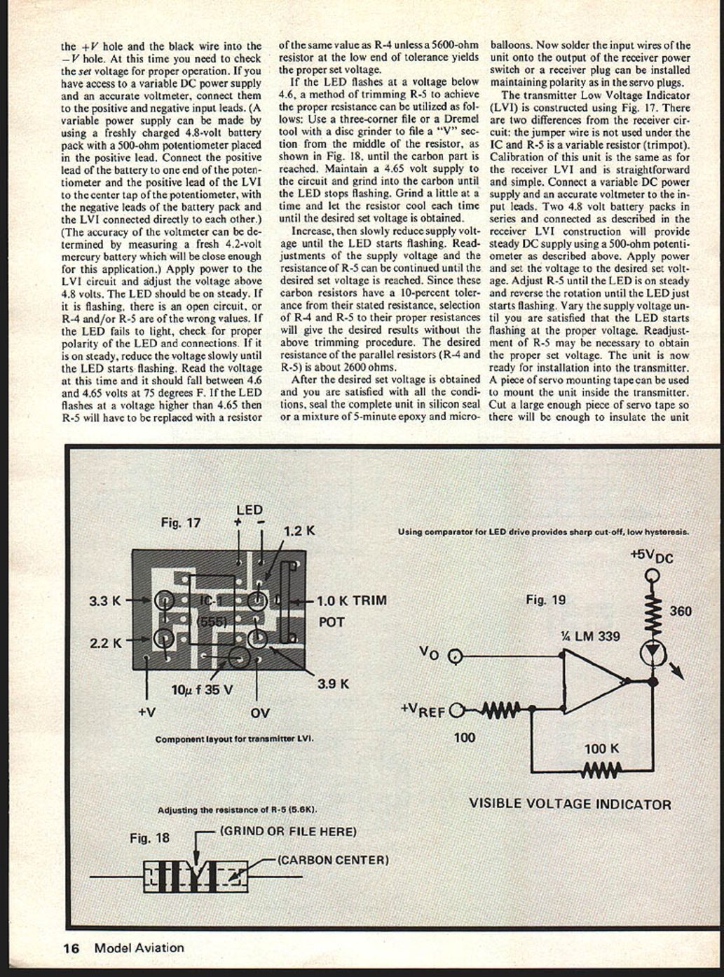
The transmitter unit is assembled exactly the same as the receiver unit except for component values shown in Fig. 17. The printed circuit foil and parts layout is shown in Figs. 14 and 15 and the overlays in Figs. 16 and 17. the +V hole and the black wire into the −V hole. At this time you need to check the set voltage for proper operation. If you have access to a variable DC power supply and an accurate voltmeter, connect them to the positive and negative input leads. (A variable power supply can be made by using a freshly charged 4.8-volt battery pack with a 500-ohm potentiometer placed in the positive lead. Connect the positive lead of the battery to one end of the potentiometer and the positive lead of the LVI to the center tap of the potentiometer, with the negative leads of the battery pack and the LVI connected directly to each other.) (The accuracy of the voltmeter can be determined by measuring a fresh 4.2-volt mercury battery which will be close enough for this application.) Apply power to the LVI circuit and adjust the voltage above 4.8 volts. The LED should be on steady. If it is flashing, there is an open circuit, or R-4 and/or R-5 are of the wrong values. If the LED fails to light, check for proper polarity of the LED and connections. If it is on steady, reduce the voltage slowly until the LED starts flashing. Read the voltage at this time and it should fall between 4.6 and 4.65 volts at 75 degrees F. If the LED flashes at a voltage higher than 4.65 then R-5 will have to be replaced with a resistor of the same value as R-4 unless a 5600-ohm resistor at the low end of tolerance yields the proper set voltage.
If the LED flashes at a voltage below 4.6, a method of trimming R-5 to achieve the proper resistance can be utilized as follows: Use a three-corner file or a Dremel tool with a disc grinder to file a "V" section from the middle of the resistor, as shown in Fig. 18, until the carbon part is reached. Maintain a 4.65 volt supply to the circuit and grind into the carbon until the LED stops flashing. Grind a little at a time and let the resistor cool each time until the desired set voltage is obtained.
Increase, then slowly reduce supply voltage until the LED starts flashing. Readjustments of the supply voltage and the resistance of R-5 can be continued until the desired set voltage is reached. Since these carbon resistors have a 10-percent tolerance from their stated resistance, selection of R-4 and R-5 to their proper resistances will give the desired results without the above trimming procedure. The desired resistance of the parallel resistors (R-4 and R-5) is about 2600 ohms.
After the desired set voltage is obtained and you are satisfied with all the conditions, seal the complete unit in silicon seal or a mixture of 5-minute epoxy and micro-balloon. Now solder the input wires of the unit onto the output of the receiver power switch or a receiver plug can be installed maintaining polarity as in the servo plugs.
The transmitter Low Voltage Indicator (LVI) is constructed using Fig. 17. There are two differences from the receiver circuit: the jumper wire is not used under the IC and R-5 is a variable resistor (trimpot). Calibration of this unit is the same as for the receiver LVI and is straightforward and simple. Connect a variable DC power supply and an accurate voltmeter to the input leads. Two 4.8 volt battery packs in series and connected as described in the receiver LVI construction will provide steady DC supply using a 500-ohm potentiometer as described above. Apply power and set the voltage to the desired set voltage. Adjust R-5 until the LED is on steady and reverse the rotation until the LED just starts flashing. Vary the supply voltage until you are satisfied that the LED starts flashing at the proper voltage. Readjustment of R-5 may be necessary to obtain the proper set voltage. The unit is now ready for installation into the transmitter. A piece of servo mounting tape can be used to mount the unit inside the transmitter. Cut a large enough piece of servo tape so there will be enough to insulate the unit.
Temperature stability — The LVI temperature stability is determined by several components. Temperature-voltage-current graphs (Figs. 12 and 13) show that on a cold day sufficient power will remain after the LED flashes to continue flying up to 30 minutes; on a very hot day you may have to stop flying immediately. Considering the fact that the temperature inside an aircraft fuselage can be much hotter than the outside air temperature, circuit operation will vary with temperature unless compensated. Such compensation can add considerable cost. Complete circuit Figs. 14 and 15 present PC foil layout for receiver LVI and transmitter LVI respectively. Figs. 16 and 17 present overlays that show parts placement and component identification. The following presents construction details. from the transmitter case to avoid shorts. Connect the input leads to the power switch output, observing polarity. Drill a 1/4-in. hole where desired for the LED to be mounted. Place a 1/4-in. grommet into the hole and then place the LED into the grommet. The unit is now ready for operation.
Supplement: Mr. Duffield has specified the Lafayette 555 IC Timer because it performs in the manner indicated in the Temperature-Voltage-Current graphs. Another source, the 555 IC Timer, operates directly opposite; that is, the IC Timer raises the set voltage with higher temperature and vice versa.
The LVI described by Mr. Duffield is somewhat more dependent on component temperature stability; is a bit less expensive in that a Zener is not required; but can be calibrated accurately. The receiver LVI is compact and draws only about 10 milliamps with a temperature stability of ±3 percent.
Components for all of the preceding or complete units can be obtained from Ace R/C, Higginsville, MO 64037. Mr. Duffield also will welcome inquiries for complete parts package or for complete units for his LVI's at P.O. Box 72, Thomaston, TX 77889.
There's no doubt that the preceding units represent a pretty deluxe approach to the problem. If one is satisfied with a simple on-off indication at the critical voltage, then the simple LED indicator suffices. The real problem is to get a sharp, repeatable cut off and low hysteresis. The Signetics data sheets for the LM339 comparator show a tentative approach. Fig. 19 presents the logic diagram. A comparator is an extremely sensitive device. VREF can be provided by a Zener divider. Whenever V0 degrades below VREF, the comparator will swing sharply, cutting off the LED.
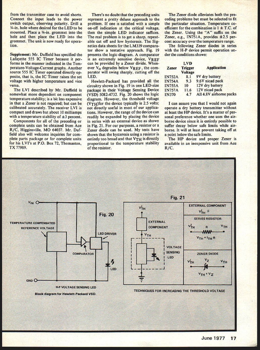
Hewlett-Packard has provided all the circuitry shown in Fig. 19 in one LED-size package in their Voltage Sensing Device (VSD) 5082-4732. Fig. 20 shows the logic diagram. However, the threshold voltage (VTH) for the device typically is 2.5 volts; not directly useful in most of our applications. However, the range of the device can readily be expanded by placing the device in series with an external component as shown in Fig. 21. For our purposes, a resistor or a Zener diode can be used. My tests have shown that the hysteresis using a resistor is entirely too broad and that VTH is directly proportional to the temperature stability of the resistor.
The Zener diode alleviates both the preceding problems but must be selected to fit the particular situation. Temperature coefficient for the combination is 1 ± T.C. of the Zener. Using the "A" suffix on the Zener, e.g., 1N751A, provides ±2.5 percent accuracy over the temperature range. The following Zener diodes in series with the H-P device permit operation under the conditions shown:
- Zener LVD Trigger Application
- 1N752A 8.1 9V dry battery
- 1N754A 9.3 9.6V nicad pack
- 1N755A 10 12V dry battery
- 1N757A 11.6 12V nicad pack
- 1N370 4.7 All 4.8V airborne packs
I can assure you that I would not again operate a dry battery transmitter without at least the HP device. It's a matter of personal preference whether one uses the airborne device since it is entirely possible to suffer decay below safe limits while airborne. It will at least prevent taking off at a point below the safe limits.
The HP device and proper Zener is available in an inexpensive unit from Ace R/C.
Transcribed from original scans by AI. Minor OCR errors may remain.

