
Luton Minor Prototype
Dee B. Mathews
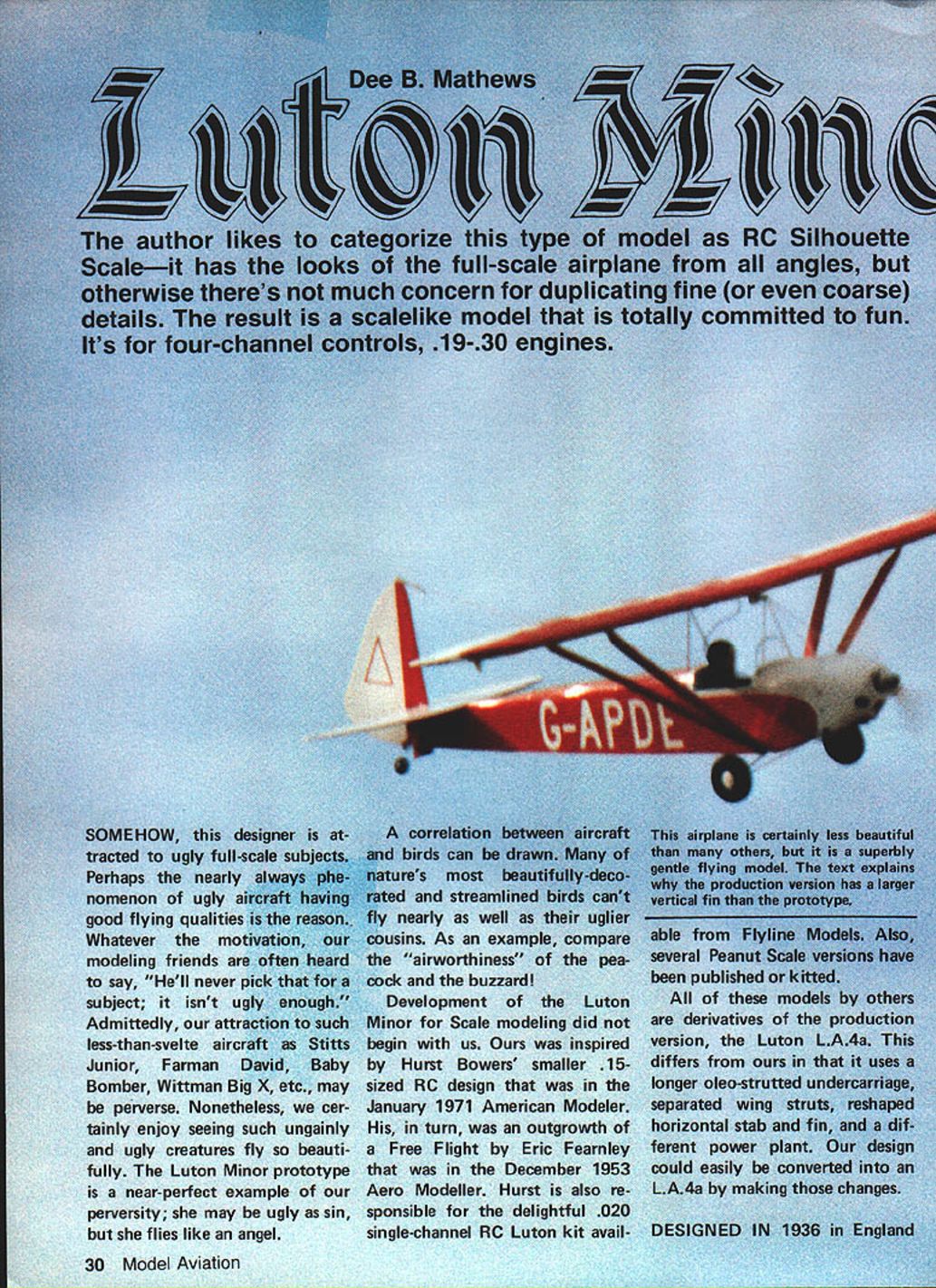
The author likes to categorize this type of model as RC Silhouette Scale — it has the looks of the full-scale airplane from all angles, but otherwise there's not much concern for duplicating fine (or even coarse) details. The result is a scalelike model that is totally committed to fun. It's for four-channel controls, .19–.30 engines.
Somehow, this designer is attracted to ugly full-scale subjects. Perhaps the nearly universal phenomenon of ugly aircraft having good flying qualities is the reason. Whatever the motivation, our modeling friends are often heard to say, "He'll never pick that for a subject; it isn't ugly enough." Admittedly, our attraction to such less-than-svelte aircraft as the Stitts Junior, Farman David, Baby Bomber, Wittman Big X, etc., may be perverse. Nonetheless, we certainly enjoy seeing such ungainly and ugly creatures fly so beautifully. The Luton Minor prototype is a near-perfect example of our perversity; she may be ugly as sin, but she flies like an angel.
A correlation between aircraft and birds can be drawn. Many of nature's most beautifully decorated and streamlined birds can't fly nearly as well as their uglier cousins. As an example, compare the "airworthiness" of the peacock and the buzzard.
Development of the Luton Minor for scale modeling did not begin with us. Ours was inspired by Hurst Bowers' smaller 15-sized RC design that was in the January 1971 American Modeler. His, in turn, was an outgrowth of a free-flight design by Eric Fearnley that appeared in the December 1953 Aero Modeller. Hurst is also responsible for the delightful .020 single-channel RC Luton kit available from Flyline Models. Several Peanut Scale versions have also been published or kitted.
All of these models by others are derivatives of the production version, the Luton L.A.4a. This differs from the prototype in that it uses a longer oleo-strutted undercarriage, separated wing struts, a reshaped horizontal stab and fin, and a different power plant. Our design could easily be converted into an L.A.4a by making those changes.
This airplane is certainly less beautiful than many others, but it is a superbly gentle flying model. The text explains why the production version has a larger vertical fin than the prototype.
Designed in 1936 in England by C.H. Latimer-Needham, the original L.A.2 was a tandem-winged concept with one wing placed above the fuselage on a pylon and the second placed immediately behind the trailing edge of the first, mounted on the top fuselage stringers. The Luton firm developed this rather odd configuration in an attempt to provide a safer alternative to the French Flying Flea. The French design had proven very popular with home-builders throughout Europe; unfortunately, its flight characteristics were so dangerous that it had been outlawed.
With the L.A.2, it was hoped that the addition of a conventional stabilizer and ailerons would cure the nose-down instability problem the Flea had exhibited.
Test flying, which turned out to be a very short program, revealed poor climb performance. A decision was then made to convert the L.A.2 into a conventional high-wing monoplane with the designation L.A.4. (The L.A.3 design was a streamlined L.A.1 of pusher configuration. This was called the Buzzard—see how I snuck that in?)
A low-aspect-ratio wing for the L.A.4 was chosen for ease of construction and hangaring. The design was intended for the home-builder from kits sold by Luton. Every effort was made to provide a foolproof design both in construction and flight. The red triangle on the fin had the legend, "Safety First."
After considerable flight testing, the L.A.4 was redesigned to become the L.A.4a; in this configuration it has been built around the world. Power has ranged from the "bottom two-thirds of an Anzani" of the prototype to the license-built Aeronca two-cylinder J.A.P. seen in photos, to contemporary V.W. units.
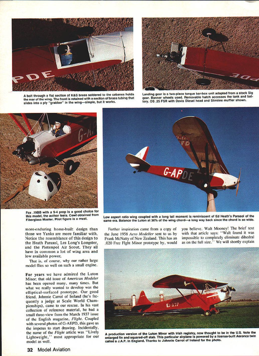
Latimer-Needham's design has become a legend for its superb stability, viceless handling, excellent economy of construction and operation, and delightful "ugliness." On a worldwide basis, the Luton Minor has been a vastly more enduring home-built design than many American designs. Notice the resemblance of this design to the Heath Parasol, Les Long's Longster, and the Pietenpol Air Scout. They all have in common a lot of wing area and low available power — which is why our rather large model flies so well on such a small engine.
For years we have admired the Luton Minor; that old issue of American Modeler has been opened many, many times. But what we really wanted to develop was the elliptical-surfaced prototype. Our good friend Johnnie Carrol of Ireland (he's frequently a judge at Scale World Championships) came to our rescue. In his vast collection of reference material he had a small three-view from the March 1937 issue of the English magazine Flight. Coupled with several photos of G‑AEPD, this gave us the impetus to start drawing. Incidentally, the name of the Flight article was "Lively Lightweight," most appropriate for our model as well.
Further inspiration came from a copy of the June 1958 Aero Modeller sent to us by Frank McNatty of New Zealand. This has an .020 free-flight Minor prototype by, would you believe, Walt Mooney! The brief text with that article says: "Walt found it was impossible to completely eliminate dihedral on the full size." We will shortly explain what Walt meant.
Note: The prototype we used for drawings and scale-detail studies was G‑AEPD (photographs and a small three-view from the March 1937 issue of Flight provided the references). Thanks to Johnnie Carrol of Ireland for the photo and reference material.
As far as we know, this is the first published RC version of the Luton Minor L.A.4 (prototype). This rather unusual model has been a pure delight for us to design, build, and fly. We recommend it to builders and pilots of all skill levels.
Construction
Wire parts
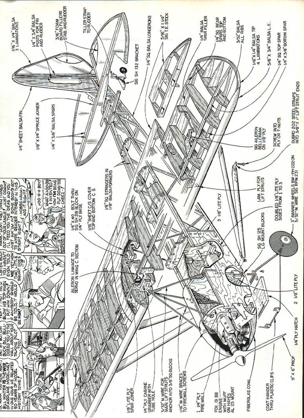
If any portion of this design would frighten away a prospective builder, it would probably be the cabane structure. Therefore, let's get started here.
The cabane pieces are bent in pairs from 3/32-in. music wire. This will bend rather easily if a large Vise-Grip plier and bench vise are used. A cutoff wheel in a motor tool is also most helpful. Always discard mis-bent pieces; rebending is almost always unsatisfactory.
Use the drawing as a pattern to develop one half, then bend the second to match it. The top right angles need to be bent parallel to each other. The bottom bends can be left over-length — cut them after installation through the laminated ply sides.
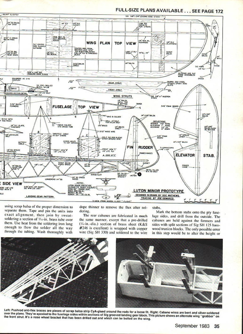
Position the two halves over the drawing, using scrap balsa of the proper dimension to separate them. Tape and pin the units into exact alignment, then join by sweat-soldering a section of 1/32-in. brass tube over them. Use heat from the soldering iron long enough to flow the solder all the way through the tubing. Wash thoroughly with dope thinner to remove the flux after soldering.
The rear cabanes are fabricated in much the same manner, except that a pre-drilled (1/4-in.-dia.) section of brass sheet (K&S #246 is excellent) is wrapped with copper wire (Sig SH 330) and soldered to the wire stubs.
Mark the bottom stubs onto the ply fuselage sides, and drill from the outside. The cabanes are held against the formers and sides with split sections of Sig SH 125 basswood trunnion blocks. The only possible error in this step would be to alter the height or fore-and-aft position of the cabane — do not place the mid-line to one side. Measure accurately!
The forward struts are held to the firewall with #4 sheet-metal screws running through loops bent in the wire. They can be retained by soldering them onto the brass tube or wrapping with soft copper wire. These should be installed after finishing.
The landing gear can be modified from a Sig RP-BM-231 unit, or it can be made from 5/32-in. music wire. A torque-wire unit of this type is more than adequate to absorb any forces; the drag wire is purely for decoration (ours was bent from a section of welding rod; loops hold it to the mains, and the firewall brackets are plastic cable connectors we found at a Radio Shack store).
Wing struts
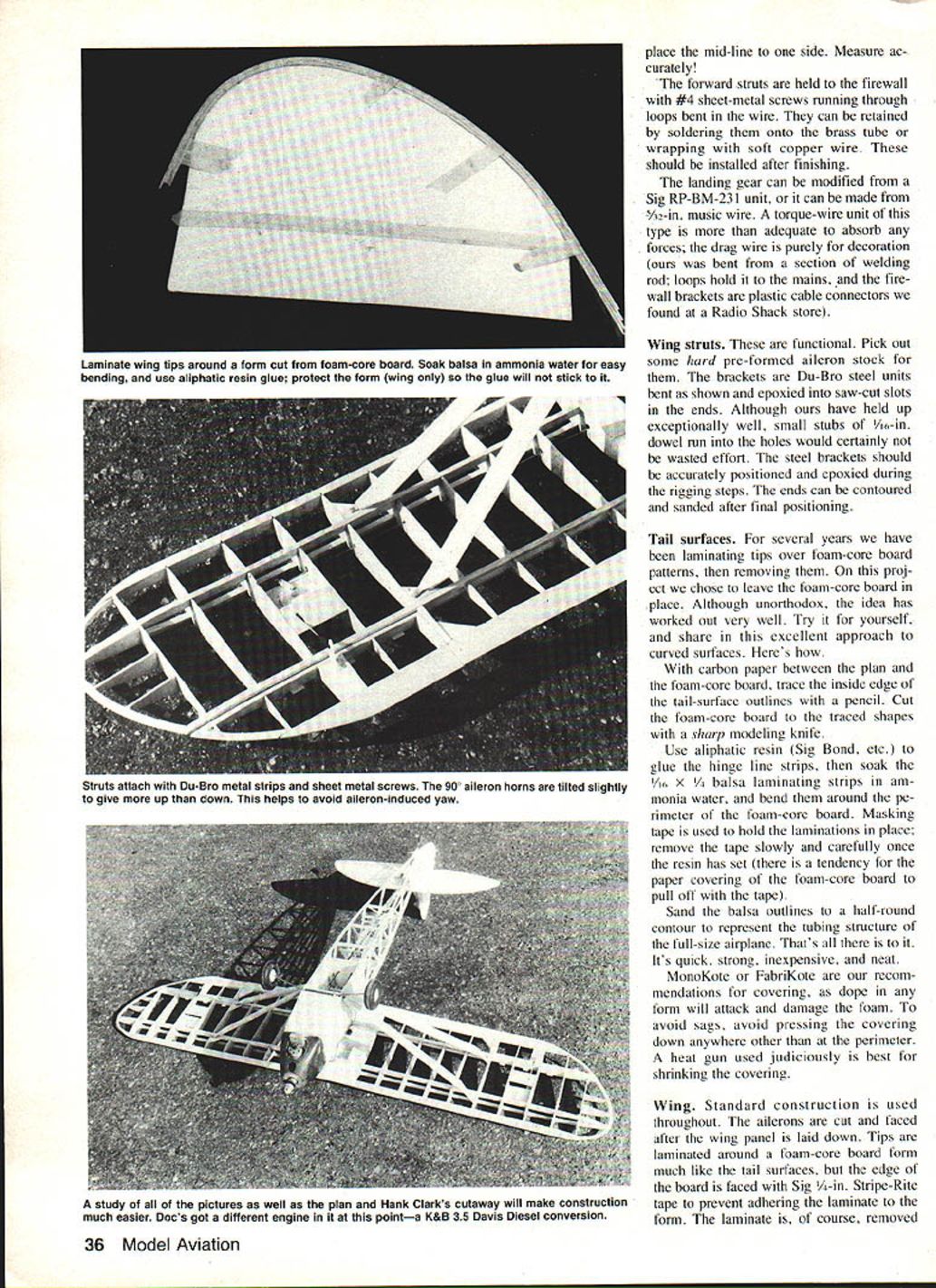
These are functional. Pick out some hard pre-formed aileron stock for them. The brackets are Du-Bro steel units bent as shown and epoxied into saw-cut slots in the ends. Although ours have held up exceptionally well, small stubs of 1/16-in. dowel run into the holes would certainly not be wasted effort. The steel brackets should be accurately positioned and epoxied during the rigging steps. The ends can be contoured and sanded after final positioning.
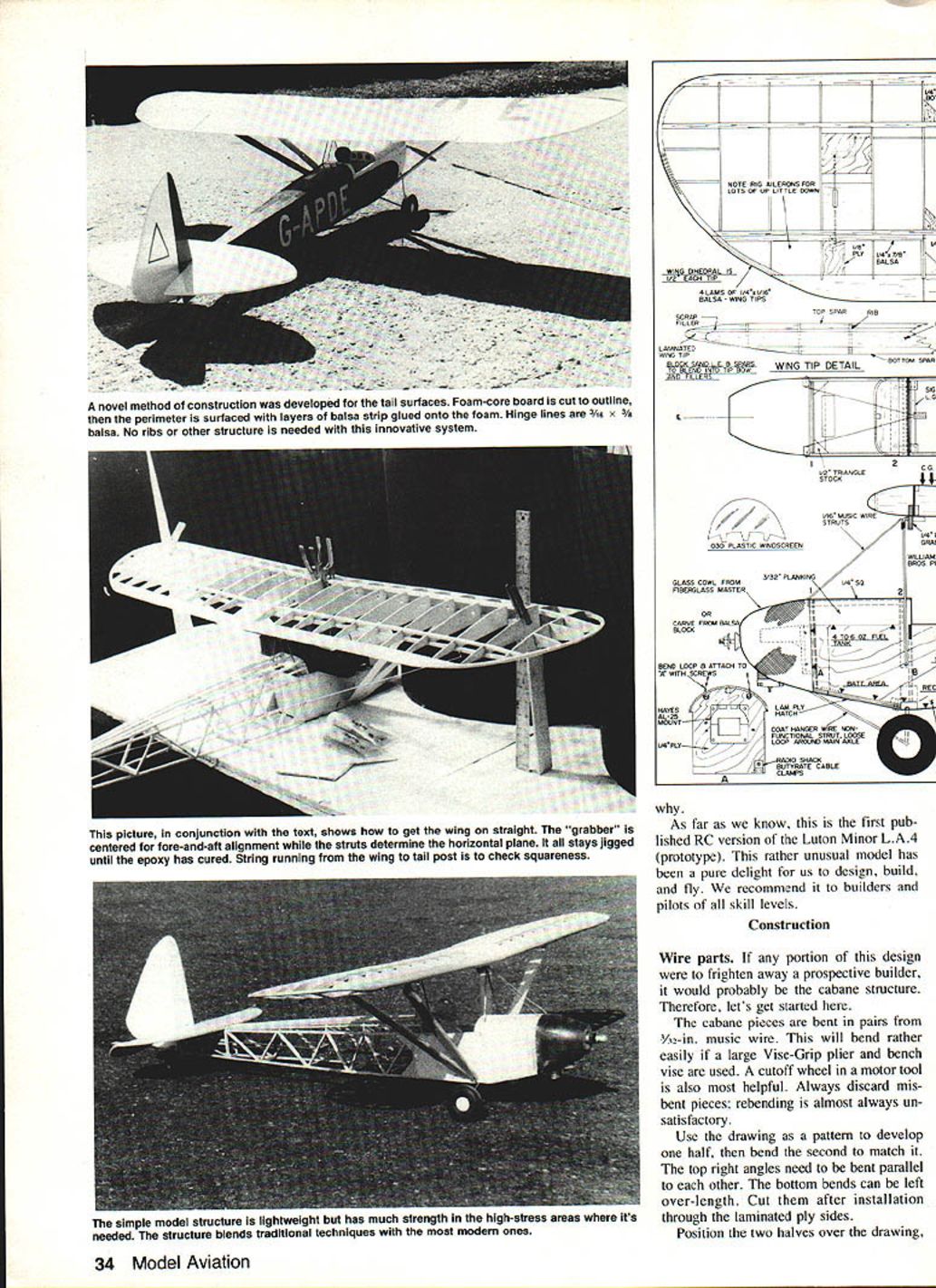
Tail surfaces
For several years we have been laminating tips over foam-core board patterns, then removing them. On this project we chose to leave the foam-core board in place. Although unorthodox, the idea has worked out very well. Try it for yourself, and share in this excellent approach to curved surfaces. Here's how:
- With carbon paper between the plan and the foam-core board, trace the inside edge of the tail-surface outlines with a pencil.
- Cut the foam-core board to the traced shapes with a sharp modeling knife.
- Use aliphatic resin (Sig Bond, etc.) to glue the hinge-line strips, then soak the 1/16 x 1/4 balsa laminating strips in ammonia water and bend them around the perimeter of the foam-core board.
- Masking tape is used to hold the laminations in place; remove the tape slowly and carefully once the resin has set (there is a tendency for the paper covering of the foam-core board to pull off with the tape).
- Sand the balsa outlines to a half-round contour to represent the tubing structure of the full-size airplane.
It's quick, strong, inexpensive, and neat. MonoKote or FabriKote are our recommendations for covering, as dope in any form will attack and damage the foam. To avoid sags, avoid pressing the covering down anywhere other than at the perimeter. A heat gun used judiciously is best for shrinking the covering.
Wing
Standard construction is used throughout. The ailerons are cut and faced after the wing panel is laid down. Tips are laminated around a foam-core board form much like the tail surfaces, but the edge of the board is faced with Sig 1/16-in. Stripe-Rite tape to prevent adhering the laminate to the form. The laminate is, of course, removed after drying overnight.
Dihedral gussets are custom cut to fit saw cuts made flush against the spar faces.
The threaded block is mounted in an appropriate cut-out in the joined center ribs with the ply sheet in place. The 1/4-ply "grabber" is trial-fitted but not epoxied until the rigging step.
The aileron linkage should be set up with differential throws by angling the 90° bellcranks and positioning the horns. We used Goldberg AC 246 connectors, but Du-Bro 183 hardware (or even a simple wire stub) would work just as well.
Planking other than the ply floor should be left off until the jigging step has been completed. This allows the use of clothespins and/or clamps to hold the center section while adjusting.
Fuselage
Construction is in the classical way. Two identical sides are joined with bulkheads and crosspieces to form a box. Three bulkheads interlock into the laminated ply sides, and the tail post is pulled together and joined over the top view drawing. The laminated ply is two layers of Lite Ply (poplar) joined with a thin layer of 5-minute epoxy and weighted on a flat surface.
Cabane wires should be installed prior to putting in the turtle-deck and nose sheeting. The sheeting can be cut to clear the wire, joined to the sides, and pulled down onto the 1/4 x 1/4 strip. Glue with thin beads of thick CyA. When the turtle-deck stringers are in place, trim off any projections of the formers between them to avoid a "starved horse" look. Build up a layer of scrap balsa around the wire.
The tail-wheel bracket is screwed onto a ply base, and the tiller arm is held to the rudder with a strip of sheet metal run under either side of the horn. As an alternative, a skid of wire would be more scale-like, and it would work satisfactorily.
The cowl is held to the firewall with small sections of basswood and #4 sheet-metal screws. Openings must be made in the cowl for choking and air passage around the shaft and out around the head and muffler. The fiberglass unit has sufficient strength to remain usable even after large chunks are cut away. Sufficient room is available for mounting the engine sideways, upright, or inverted.
Warning: The long tail and short nose moments of the Luton Minor require careful attention to weight distribution. A 500 mAh battery pack was used on our model, and the weight was needed! (As a rule, we feel we have done a good job of engineering a design if it requires no ballast. There is just no way to do that on the Luton.)
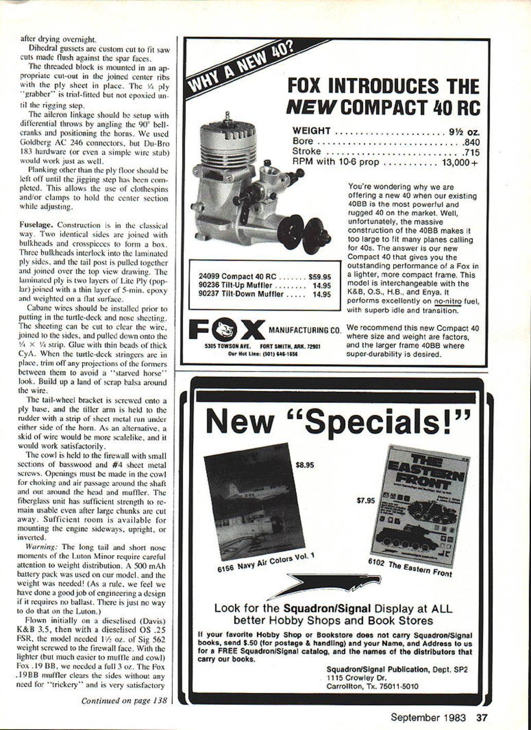
The model was flown initially on a dieselized (Davis) K&B 3.5 and then with a dieselized OS .25 FSR; it needed 1½ oz. of Sig 562 weight screwed to the firewall face. With the lighter but much easier to muffle and cowl Fox .19 BB, we needed a full 3 oz. The Fox .19BB muffler clears the sides without any need for "trickery" and is very satisfactory, turning a 9 x 6 prop. Idle is marvelously slow and reliable, mid-range is excellent, and adjustments are a breeze.
Luton Minor / Mathews (Continued)
Rigging
One of the photos illustrates the technique. Start with the nylon bolt and threaded block. Measure and block up both wings exactly the same height off the board with the wing bolt screwed in. Run a string from the tail post to exactly the same point on both wing panels; keep adjusting the fore-and-aft position of the "grabber" by loosening the clothespins until it is exactly even. This dimension determines left or right thrust, and it must be zero-zero.
Once the wing panels are equal in dihedral and left-right, the "grabber" is epoxied and clamped against the wing structure. Avoid the later necessity of raising or lowering the wing incidence by carefully measuring against the flat fuselage top at this time.
After the epoxy has cured, but with the screw still jigged, glue the steel straps into the strut slots with 5-minute epoxy. The ends should be screwed into pre-drilled holes.
Rigging is not at all difficult or complex. However, it requires patience and care, so don't be in a hurry.
Covering and finishing
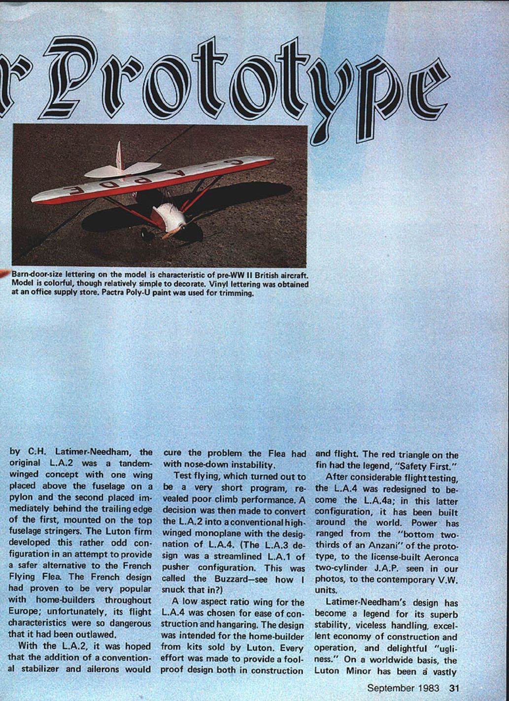
Ours has MonoKote on the wing and tail surfaces and Sig Koverall on the fuselage. The Koverall was heat-sealed over Coverite AisraLite, then heat-shrunk. Three coats of clear nitrate dope were followed with two sprayed coats of Pactra Poly-U on the fuselage.
The wing leading-edge trim is with Poly-U. Numbers are EZ-Stik vinyl — 6 in. on the wing and 4 in. on the fuselage. The pilot figure is a Williams Bros. 2½-in. standard unit painted with paint for plastic models. Banner wheels go nicely with this model.
Flying
Ground handling on the takeoff roll must be seen to be believed. This thing gets up on its mains and will run straight down the runway for a mile. Apparently, the low-to-the-ground fuselage and high-up-in-the-air wing combine to produce truly extraordinary handling.
The Luton Minor doesn't need rudder stabbing or a steerable tail wheel to get it going straight down the runway. Just point her in the direction you want, and advance the throttle. On the other hand, it tracks so darn well that it is most difficult to turn around while taxiing. (But who cares?)
The climb-out is more a function of the wing than the engine. That is, she is not intended to climb on her prop; rather, she uses speed to climb on the wing.
In a steep pull-up, such as the "clear deck" portion of a touch-and-go, be prepared to witness a strange phenomenon. If the nose gets too high, the tail waggles. The prototype vertical fin was replaced by a larger "swoopy-looking thing," and we have learned why. The stab and wing blank out the fin at high angles of attack. This produces a "fish tail" of about 50° from side to side. Even so, everything is under control. The model isn't going to drop a wing and snap-roll. She just waggles her tail in a sassy sort of a way — and goes on her merry way.
Hurst Bowers, upon learning of our model's "fish tail," wrote that he has built three different Luton Minors over the years and that they all had the tail-waggle characteristic. This seems to be a perfect example of a model duplicating an idiosyncrasy of the full-sized aircraft.
We cannot get our model to spin! Throttled way back (or dead-stick, for that matter) and fully stalled with all the aileron, elevator, and rudder we can input, she just mushes off to one side, drops her nose, and repeats the cycle. This model is extremely stable.
The Luton Minor in this size and wing loading is an exceptionally easy model to fly. It would be nice if all the RC trainers were this gentle. Loops tend to look more like hen eggs. Rolls? You've got to be kidding! The only roll this doll can do is down the runway.
So she's not acrobatic — but she is gloriously cute in the air or on the ground. Placed in half or less throttle, she putts and sputters around at unbelievably slow speeds in a most delightful and realistic manner. The long-term popularity of the Luton Minor with sport fliers stems from the pure joy of flying it. The same holds true with this model.
Everyone who flies our Luton falls in love with her. That must be the reason we constantly use the feminine gender when talking about her.
By all means, build one for yourself. You are certain to enjoy it.
Transcribed from original scans by AI. Minor OCR errors may remain.

