
Make a Lightweight Switch
by Robert Boyce
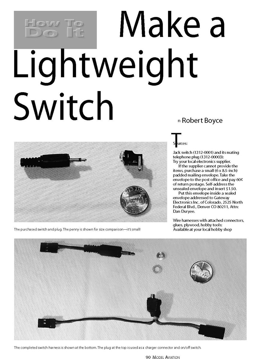
This jack switch is ideal for a small sailplane or a park flier. The miniature switch weighs one gram and is used as an on/off switch and a battery-charging connector. You turn the switch on by removing a small external telephone plug and turn it off by inserting the plug. The onboard batteries can be charged when a battery charger is connected to the plug. Having the charge connector accessible on the outside of the fuselage can be a real advantage—especially if the fuselage is packed full of electronics. The jack switch and its telephone plug can be purchased by mail order for $1.50, excluding return postage.
I have encountered no failures in more than two years of operation.
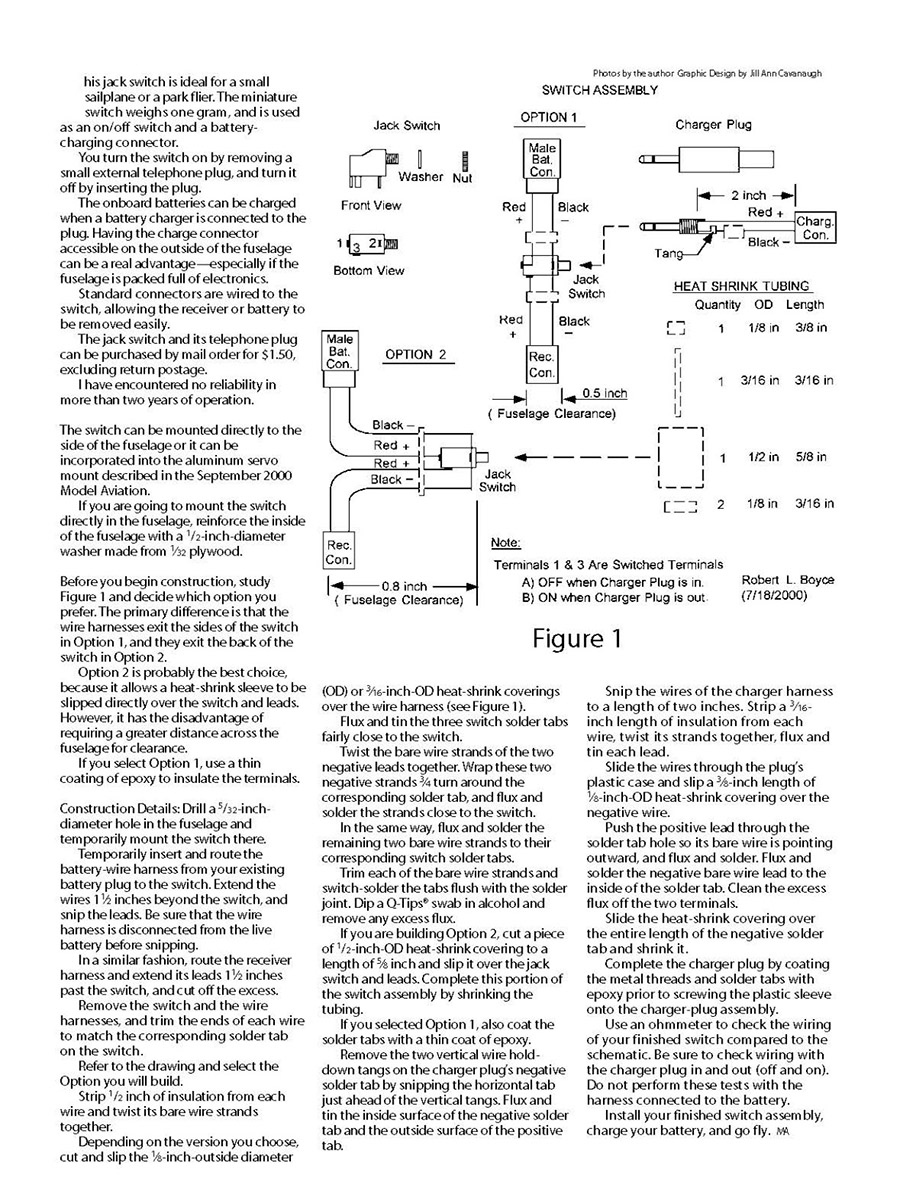
The switch can be mounted directly to the side of the fuselage or it can be incorporated into the aluminum servo mount described in the September 2000 Model Aviation. If you are going to mount the switch directly in the fuselage, reinforce the inside of the fuselage with a 1/2-inch-diameter washer made from 1/32-inch plywood. Before you begin construction, study Figure 1 and decide which option you prefer. The primary difference is that the wire harnesses exit the sides of the switch in Option 1, and they exit the back of the switch in Option 2. Option 2 is probably the best choice because it allows a heat-shrink sleeve to be slipped directly over the switch and leads; however, it requires a greater distance across the fuselage for clearance. If you select Option 1, use a thin coating of epoxy to insulate the terminals.
Construction details
- Drill a 5/32-inch-diameter hole in the fuselage and temporarily mount the switch there.
- Temporarily insert and route the battery-wire harness from your existing battery plug to the switch. Extend the wires 1 1/2 inches beyond the switch and snip the leads. Be sure that the wire harness is disconnected from the live battery before snipping.
- In a similar fashion, route the receiver harness and extend its leads 1 1/2 inches past the switch, then cut off the excess.
- Remove the switch and the wire harnesses, and trim the ends of each wire to match the corresponding solder tab on the switch.
- Strip 1/2 inch of insulation from each wire and twist its bare wire strands together.
- Depending on the version you choose, cut and slip the 1/8-inch-OD or 3/16-inch-OD heat-shrink coverings over the wire harness.
- Flux and tin the three switch solder tabs fairly close to the switch.
- Twist the bare wire strands of the two negative leads together. Wrap these two negative strands 3/4 turn around the corresponding solder tab, and flux and solder the strands close to the switch.
- In the same way, flux and solder the remaining two bare wire strands to their corresponding switch solder tabs.
- Trim each of the bare wire strands and switch-solder the tabs flush with the solder joint.
- Dip a Q-Tip swab in alcohol and remove any excess flux.
- If you are building Option 2, cut a piece of 1/2-inch-OD heat-shrink covering to a length of 5/8 inch and slip it over the jack switch and leads; then shrink the tubing.
- If you selected Option 1, coat the solder tabs with a thin coat of epoxy.
Charger-plug assembly (modification and wiring)
- Remove the two vertical wire hold-down tangs on the charger plug’s negative solder tab by snipping the horizontal tab just ahead of the vertical tangs.
- Flux and tin the inside surface of the negative solder tab and the outside surface of the positive tab.
- Snip the wires of the charger harness to a length of two inches. Strip a 3/16-inch length of insulation from each wire, twist the strands together, and flux and tin each lead.
- Slide the wires through the plug’s plastic case and slip a 3/8-inch length of 1/8-inch-OD heat-shrink covering over the negative wire.
- Push the positive lead through the solder-tab hole so its bare wire is pointing outward; flux and solder.
- Flux and solder the negative lead to the inside of the solder tab.
- Clean the excess flux off the two terminals.
- Slide the heat-shrink covering over the entire length of the negative solder tab and shrink it.
- Complete the charger plug by coating the metal threads and solder tabs with epoxy prior to screwing the plastic sleeve onto the charger-plug assembly.
Final checks and installation
- Use an ohmmeter to check the wiring of your finished switch compared to the schematic. Check wiring with the charger plug both inserted (on) and removed (off). Do not perform the tests with the harness connected to the battery.
- Install your finished switch assembly, charge your battery, and go fly.
Sources
- Jack switch (1312-0001) and its mating telephone plug (1312-00003): Try your local electronics supplier. If the supplier cannot provide the items, purchase a small (6 x 8.5-inch) padded mailing envelope. Take the envelope to the post office and pay 60¢ of return postage. Self-address the unsealed envelope and insert $1.50. Put this envelope inside a sealed envelope addressed to Gateway Electronics Inc. of Colorado, 2525 North Federal Blvd., Denver, CO 80211, Attn: Dan Duryee.
- Wire harnesses with attached connectors, glues, plywood, hobby tools: Available at your local hobby shop.
Transcribed from original scans by AI. Minor OCR errors may remain.

