
The Malmo Junior and Seaplane
THE MF 1-9 can be considered the "second generation" model of Bjorn Andreasson's original BA-7. The extremely simple construction, along with the excellent flight characteristics, evolved into many variations, including a versatile military version and the MF 1-17 Safari. Bjorn Andreasson conceived the two-place 75-hp homebuilt with an engineer at Convair, San Diego. After proving his engineering ability with the successful flight of the BA-7 in October 1958, he returned to Sweden as head of the aircraft division of A.B. Malmo Flygindustri, where he worked on advanced light-plane designs.
An improved version, the MF 1-9 Junior, with a 100-hp Continental engine, was flown in May 1961. Subsequent versions included floatplane and snow-skis models, the improved MF 1-9B trainer, and the mil-trainer for the Swedish Air Force. A series of evolutionary changes finally emerged as the versatile 200-hp MF 1-17 Safari, flown by Count Carl Gustav von Rosen for Ethiopian relief flights in 1974.
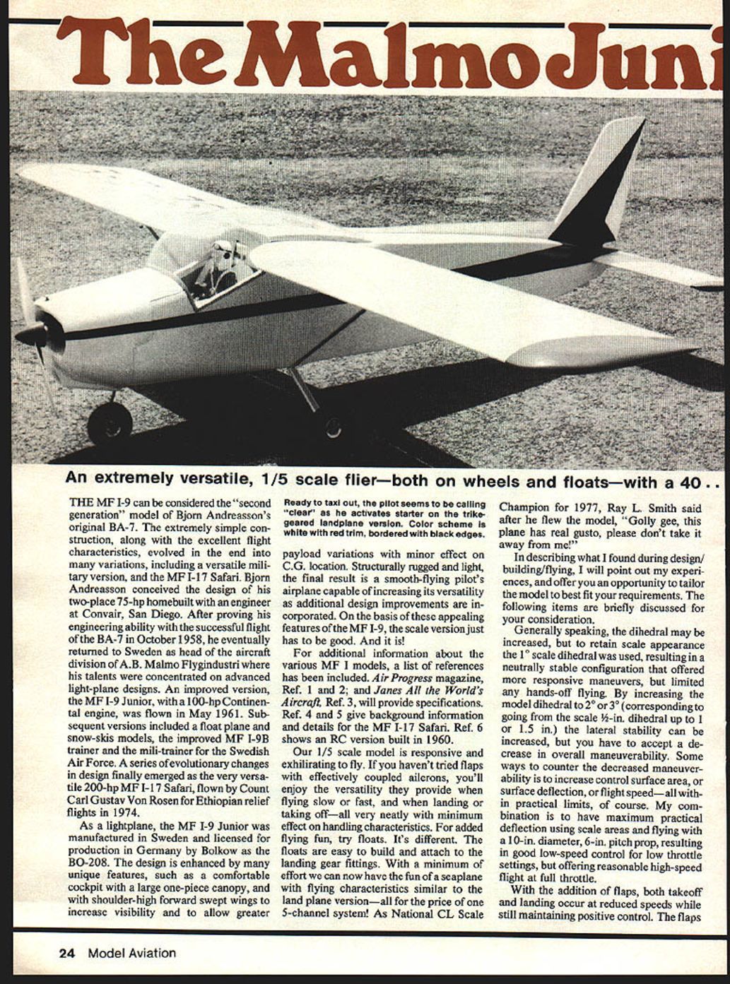
As a lightplane, the MF 1-9 Junior was manufactured in Sweden and licensed for production in Germany by Bolkow as the BO-208. The design is enhanced by many unique features: a comfortable cockpit with a large one-piece canopy, shoulder-high forward-swept wings to increase visibility, and payload variations with minor effect on C.G. Structurally rugged and light, the result is a smooth-flying pilot's airplane capable of increased versatility as improvements are incorporated.
For additional information about the various MF 1 models, see the References section at the end. Air Progress (Refs. 1 and 2) and Jane's All the World's Aircraft (Ref. 3) provide specifications. Refs. 4 and 5 give background and details on the MF 1-17 Safari. Ref. 6 shows an RC version built in 1960.
Our 1/5-scale model is responsive and exhilarating to fly. If you haven't tried flaps with effectively coupled ailerons, you'll enjoy the versatility they provide when flying slow or fast and when landing or taking off — all with minimal effect on handling characteristics. For added fun, try floats. They are easy to build and attach to the landing gear fittings. With minimal effort you can have the fun of a seaplane with flying characteristics similar to the land plane — all for the price of one 5-channel system. As National CL Scale Champion for 1977 Ray L. Smith said after he flew the model, "Golly gee, this plane has real gusto, please don't take it away from me!"
In describing what I found during design, building, and flying, I will point out my experiences and offer you opportunities to tailor the model to your requirements. The following items are discussed for your consideration.
Design notes and flight characteristics
- Dihedral: The scale dihedral is 1°, which results in a neutrally stable configuration offering more responsive maneuvers but limited hands-off flying. Increasing the model dihedral to 2° or 3° will increase lateral stability but reduce maneuverability. Ways to counter reduced maneuverability include increasing control surface area, increasing surface deflection, or increasing flight speed — within practical limits.
- Controls and prop: I fly with a 10-in diameter, 6-in pitch prop (10x6), which gives good low-speed control at low throttle and reasonable high-speed flight at full throttle. Maximum practical control deflection with scale areas provides good low-speed authority.
- Flaps: With flaps fitted, both takeoff and landing occur at reduced speeds while maintaining positive control. Flaps are effective throughout the throttle range and do not cause unusual attitude changes. During takeoff with flaps, rotating (lifting the nose wheel off first) helps stabilize the takeoff roll.
- Nose-gear: Negative caster on the nose gear may induce a divergent shimmy. The full-size airplane apparently experienced this too, as subsequent Malmo designs show a positively castered nose wheel.
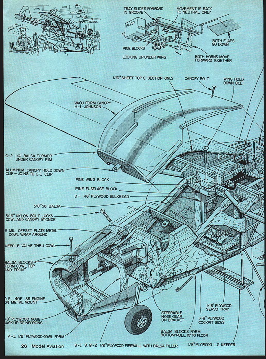
- Canopy: The large bubble canopy can be vacu-formed. Hi Johnson (see contact below) advised making a large wooden mold, coating with epoxy, sanding smooth, and pulling the canopy in a giant vacu-form. The result is a lightweight bubble requiring only minor trimming and detailing.
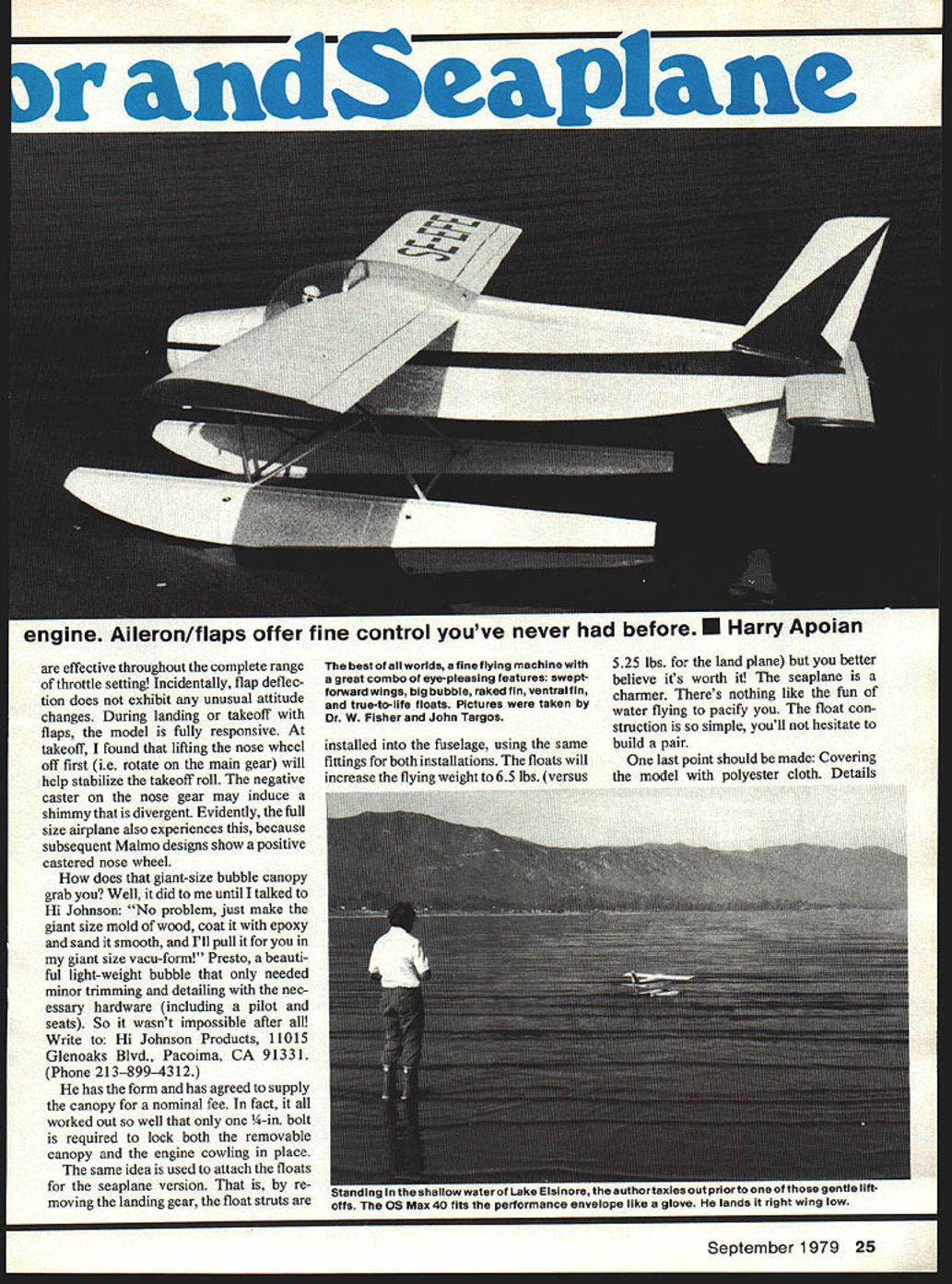
- Floats: The floats attach using the same fittings as the landing gear — remove the landing gear and install float struts into the fuselage using the same mount points. Floats increase flying weight to about 6.5 lbs (versus 5.25 lbs for the land plane). The seaplane version flies nicely; float construction is simple and worth the effort.
Contact for canopy: Hi Johnson Products, 11015 Glenoaks Blvd., Pacoima, CA 91331. Phone: (213) 899-4312.
Pictures were taken by Dr. W. Fisher and John Targos.
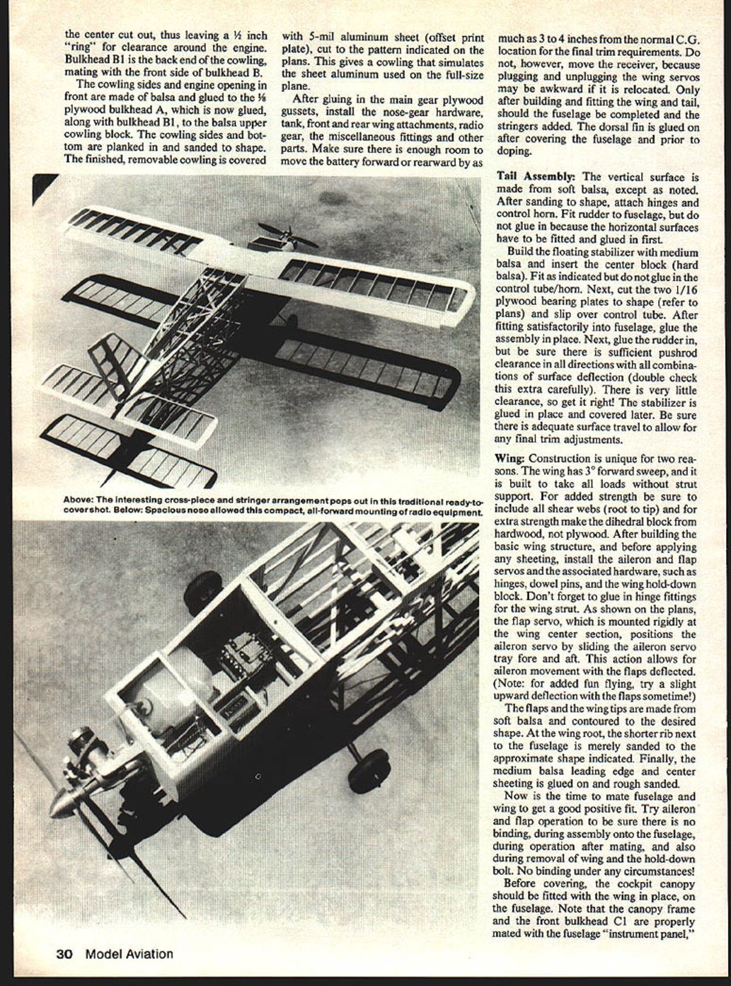
Construction Notes
It is basically a normal built-up framework covered with polyester cloth and painted with butyrate dope. There are, however, special requirements for building and assembly described below.
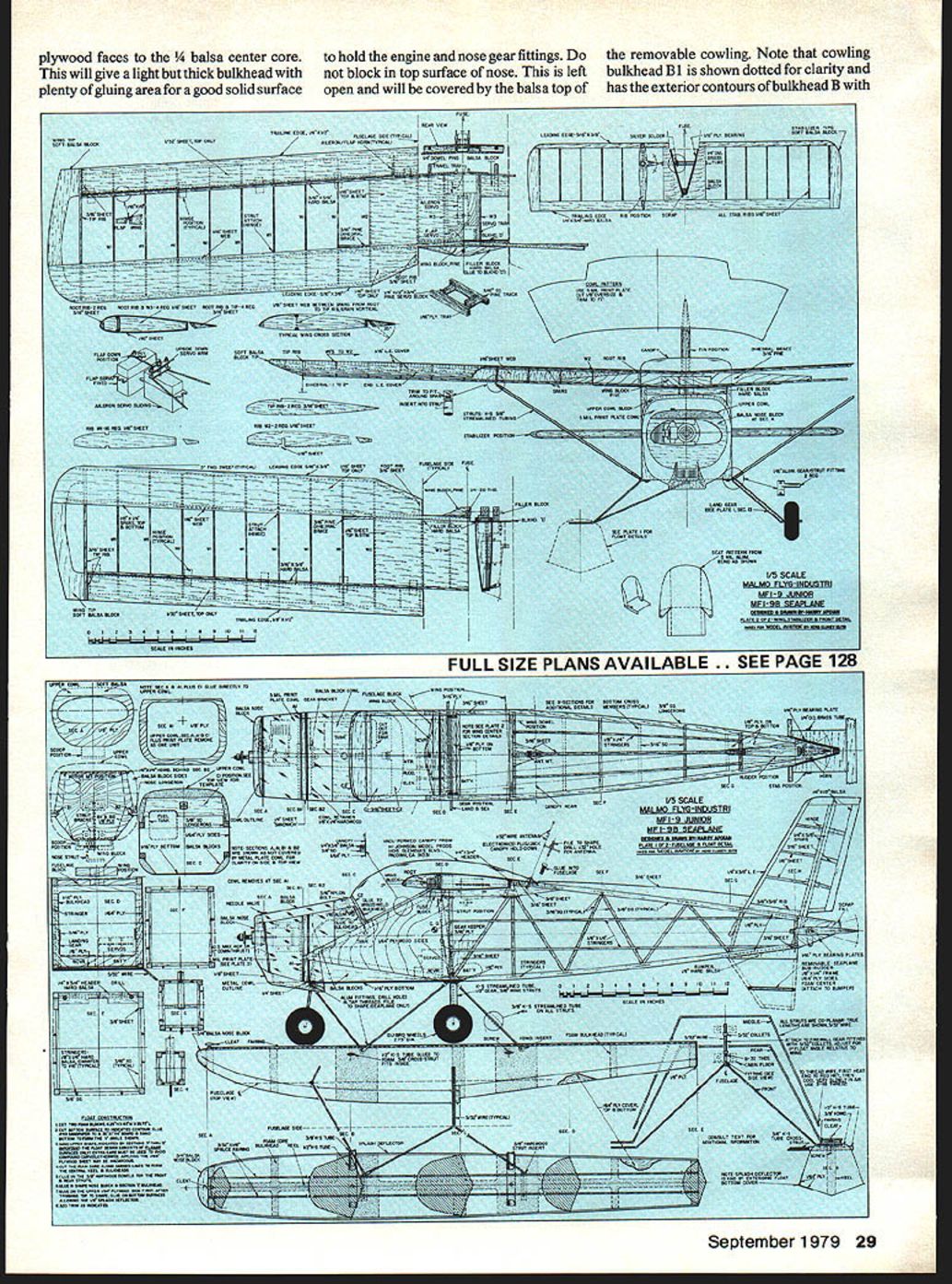
Fuselage
- Structure: Use a truss-type structure. Build the two sides as indicated on the plans.
- Longerons and diagonals: 3/16" x 3/16" diagonal members are recessed 3/16" below the 3/8" x 3/8" longerons (see body cross-sections E and F) to allow recessing the 1/8" x 1/4" stringers. Do not glue stringers in place until ready to cover — leave open spaces to install and adjust controls and other fittings. After covering, recessed stringers simulate the actual aluminum skin/stringer outline.
- Forward fuselage: From the cabin area forward use 1/64" plywood sides and 1/16" plywood on the bottom (cockpit floor). Soft balsa filler blocks form the nose contours and are glued to bulkhead B.
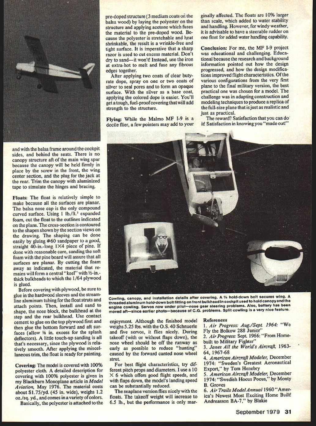
- Cowling bulkheads: Make the cowling bulkhead with plywood faces glued to a 1/4" balsa center core to give a light but thick bulkhead with good gluing area for engine and nose gear fittings. Do not block in top surface of nose — leave open for removable cowling.
- Bulkhead B1 is shown dotted on the plans: it has the exterior contours of bulkhead B with the center cut out (leaving a 1/4" ring for engine clearance). B1 is the back end of the cowling and mates with bulkhead B.
- Cowling sides and the engine opening are made from balsa and glued to 1/8" plywood bulkhead A, then glued (with B1) to the balsa upper cowling block. Plank and sand cowling sides and bottom to shape.
- Finish the removable cowling with 5-mil aluminum sheet (offset print plate) cut to plan pattern to simulate sheet aluminum.
- Final assembly: After gluing main gear plywood gussets, install nose-gear hardware, tank, front and rear wing attachments, radio gear, and miscellaneous fittings. Allow room to move the battery forward or rearward 3–4 inches from the normal C.G. for final trim. Do not move the receiver (plugging/unplugging wing servos may be awkward if relocated).
- Completion: Only after building and fitting wing and tail should the fuselage be completed and the stringers added. Glue the dorsal fin on after covering and prior to doping.
Tail assembly
- Vertical surface: Made from soft balsa except where noted. Sand to shape, attach hinges and control horn. Fit the rudder to the fuselage but do not glue in until the horizontal surfaces have been fitted and glued.
- Stabilizer: Build the floating stabilizer from medium balsa and insert the center block of hard balsa. Fit as indicated but do not glue in the control tube/horn initially.
- Bearings and control tube: Cut two 1/16" plywood bearing plates to shape (refer to plans) and slip over the control tube. After satisfactory fit in the fuselage, glue the assembly in place. Then glue the rudder in, ensuring sufficient pushrod clearance for all combinations of surface deflection — double-check this carefully.
- Final: Glue the stabilizer in place and cover later. Ensure adequate surface travel for final trim adjustments.
Wing
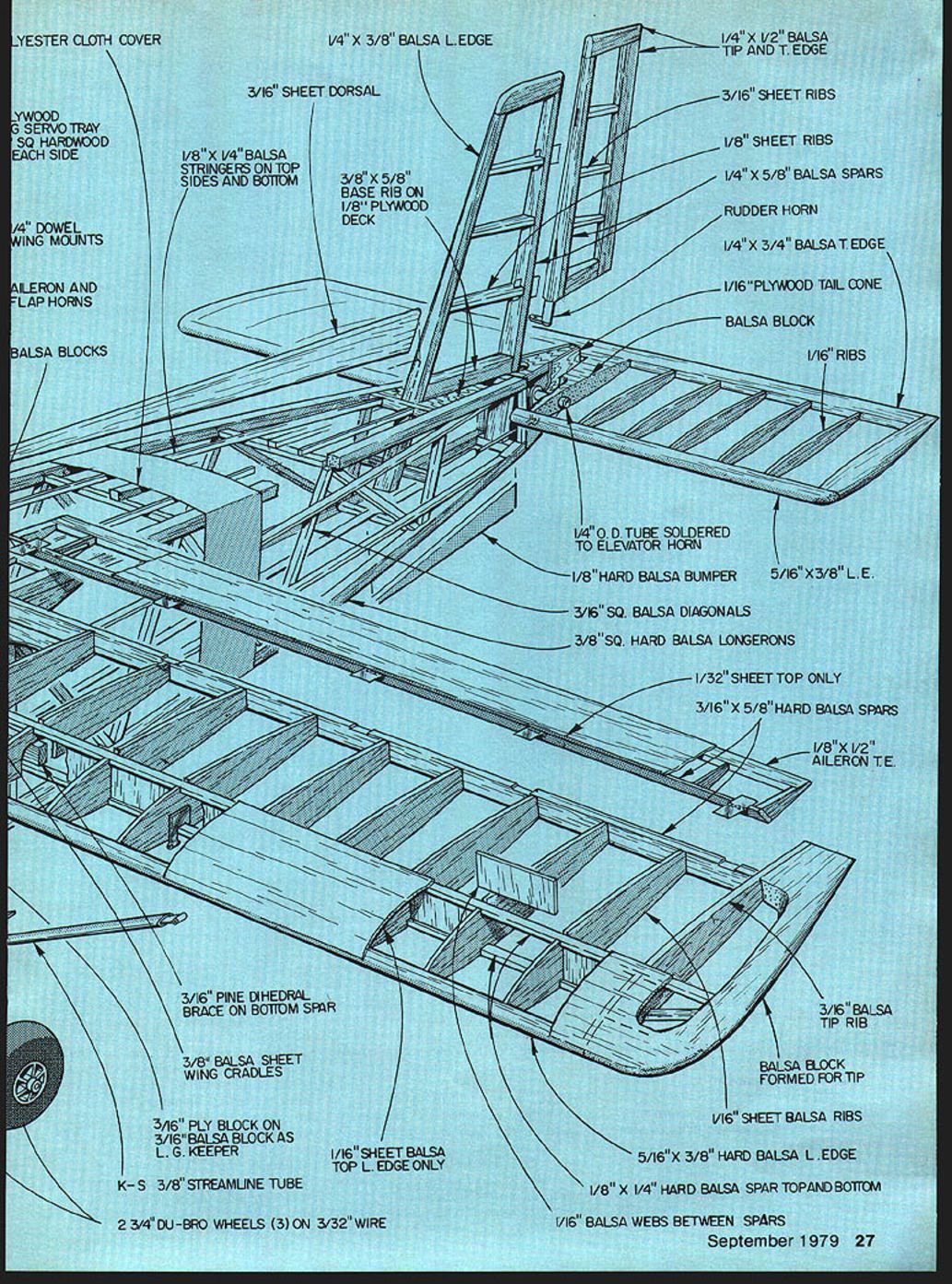
- Unique features: The wing has 3° forward sweep and is built to take all loads without strut support. Include all shear webs (root to tip). Make the dihedral block from hardwood for extra strength (not plywood).
- Installation before sheeting: After building the basic wing structure, but before sheeting, install aileron and flap servos and associated hardware (hinges, dowel pins, wing hold-down block). Glue in hinge fittings for the wing strut.
- Flap/aileron coupling: The flap servo, mounted rigidly at the wing center section, positions the aileron servo by sliding the aileron servo tray fore and aft. This allows aileron movement with the flaps deflected. Note: try a slight upward aileron deflection with flaps for interesting handling.
- Tip and flap construction: Flaps and wing tips are made from soft balsa and contoured to shape. At the wing root, the shorter rib next to the fuselage is sanded to approximate the indicated shape. Glue medium balsa leading edge and center sheeting and rough sand.
- Mating: Mate fuselage and wing to get a good positive fit. Check aileron and flap operation for binding during assembly, after mating, and during wing removal. No binding under any circumstances.
- Canopy fitting: Before covering, fit the cockpit canopy with the wing in place on the fuselage. Ensure the canopy frame and front bulkhead C1 are mated with the instrument panel and balsa frame around the cockpit sides and behind the seats. There is no canopy structure aft of the main wing spar; the canopy is held by a front screw, the wing center section, and a rear jack plug. Trim canopy with aluminized tape to simulate hinges and bracing.
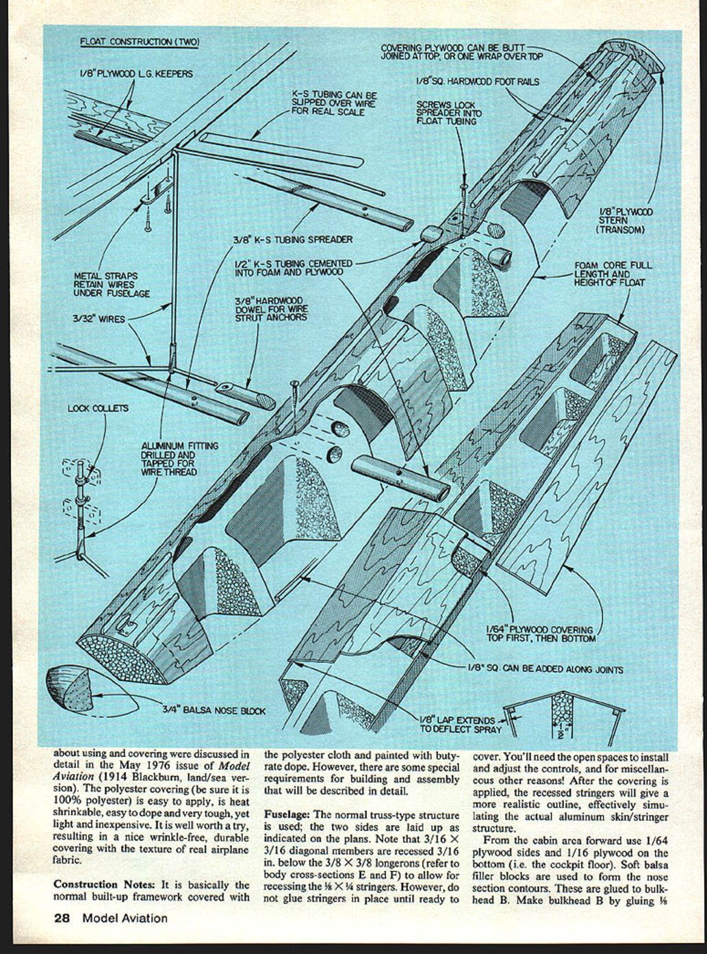
Floats
- Construction: The floats are relatively simple because all surfaces are planar; only the balsa nose cap is compound-curved. Using 1 lb./cu. ft. expanded foam, cut the floats to the plan outlines. Contour the cross-sections to the plan sections.
- Shaping: Secure #60 sandpaper to a straight 40-in. 1x4 pine board and sand the foam; this helps ensure planar surfaces. Cut foam away as indicated so remaining material forms a central keel with 1/8" thick bulkheads to which 1/64" plywood is glued.
- Internal fittings: Before covering with plywood, glue in hardwood sleeves and the streamline aluminum tubing for float struts and attach points. Install and sand the nose block, the bulkhead at the step, and the rear bulkhead.
- Plywood skinning: Use contact cement to glue on the top plywood first; then glue bottom forward and aft surfaces (allow 1/8" excess for splash deflectors). Little touch-up sanding is necessary.
- Finish: Apply miscellaneous trim and paint.
Covering
- Material: Use 100% polyester cloth (be sure it is 100% polyester). A detailed description is in the Blackburn Monoplane article in Model Aviation, May 1976. The material costs about $1.75/yd. (45 in. wide), weighs 1.2 oz./sq. yd., and comes in various colors.
- Prep: Pre-dope the structure with three medium coats on balsa wood.
- Application: Lay polyester on the pre-doped structure and apply acetone to fuse the material to the pre-doped wood. Polyester is stretchable and heat-shrinkable, producing a wrinkle-free, tight surface.
- Trimming: Use a sharp razor to cut excess material. Do not sand the cloth — it won't sand smoothly. Use an iron set extra-hot to melt and fuse any fibrous edges.
- Finishing: Apply two coats of clear butyrate dope, then one or two coats of silver to seal pores and make an opaque base. With silver as the base, apply colored dope as desired. The result is a tough, fuel-proof covering that adds strength to the structure and simulates real airplane fabric.
Parts / Structural details (from plans)
- Polyester cloth cover
- Plywood servo tray
- Square hardwood each side
- 1/4" dowel wing mounts
- Aileron and flap horns
- Balsa blocks
- 1/8" x 1/4" balsa stringers (top, sides, bottom)
- 3/16" sheet dorsal
- 1/4" x 3/8" balsa leading edge
- 3/8" x 5/8" base rib on 1/8" plywood deck
- 3/16" sheet ribs
- 1/8" sheet ribs
- 1/4" x 5/8" balsa spars
- Rudder horn
- 1/4" x 3/4" balsa trailing edge
- 1/16" plywood tail cone
- 1/16" ribs
- 1/4" O.D. tube soldered to elevator horn
- 1/8" hard balsa bumper
- 5/16" x 3/8" leading edge
- 3/16" sq. balsa diagonals
- 3/8" sq. hard balsa longerons
- 1/32" sheet top only
- 3/16" x 5/8" hard balsa spars
- 1/8" x 1/2" aileron trailing edge
- 3/16" balsa tip rib
- Balsa block formed for tip
- 1/16" sheet balsa ribs
- 5/16" x 3/8" hard balsa leading edge
- 1/8" x 1/4" hard balsa spar top and bottom
- 1/16" balsa webs between spars
- 3/16" pine dihedral brace on bottom spar
- 3/8" balsa sheet wing cradles
- 3/16" ply block on 3/16" balsa block as landing-gear keeper
- 1/16" sheet balsa top leading edge only
- K&S 3/8" streamline tube
- 2-3/4" Du-Bro wheels (3) on 3/32" wire
Flying
- Weight and power: The finished model weighs about 5.25 lbs with an O.S. .40 Schnuerle engine and five servos. A 10x6 prop provides good flight speeds; with flaps down, landing speed is substantially reduced.
- Takeoff: Lift the nose wheel off the runway as early as possible to reduce "hunting" caused by the forward-canted nose wheel strut. Rotate on the mains (lift the nose wheel off first) and allow the main gear to lift to stabilize the takeoff roll.
- Props: Try different prop pitches and diameters for best characteristics.
- Seaplane: The seaplane version (floats fitted) increases weight to about 6.5 lbs but performance is only marginally affected. Floats used here are about 10% larger than scale to improve water stability. For windy conditions, consider a steerable rudder on one float for improved water handling.
Conclusion
The MF 1-9 project was both educational and challenging. Research and background information showed how the design progressed and how modifications improved flight characteristics. Of the various full-size configurations, the most practical one was chosen for the model. The challenge was adapting construction and modeling techniques to produce a realistic, practical replica.
The reward is satisfaction — you can do it and "made out!"
References
- Air Progress: Aug./Sept. 1964 — "We Fly the Bolkow 288 Junior."
- Air Progress: Sept. 1966 — "From Homebuilt to Military Fighter."
- Jane's All the World's Aircraft, 1963–64, 1967–68.
- American Aircraft Modeler, December 1974 — "Sweden's Greatest Aeronautical Export," by Tom Henebry.
- American Aircraft Modeler, December 1974 — "Swedish Hocus Pocus," by Monty B. Groves.
- Air Trails Model Annual 1960 — "America's Newest Most Exciting Home Built! Andreasson BA-7," by Blakie.
Transcribed from original scans by AI. Minor OCR errors may remain.

