
Mandarin
James A. Ruggiero
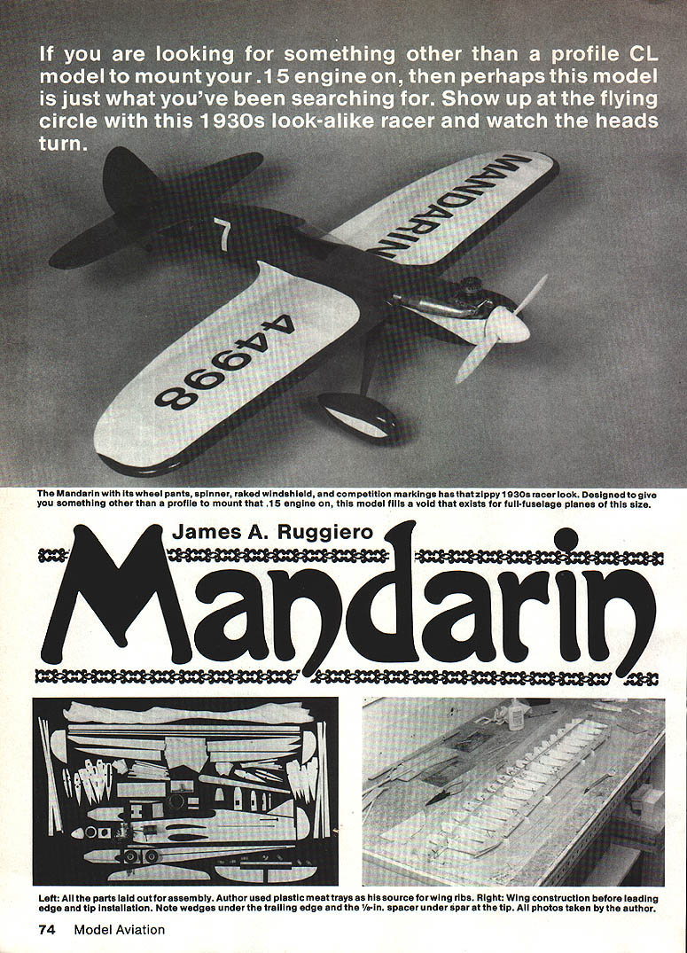
THIS AIRPLANE was designed to fill the need for a full-fuselage, stuntable control-line model for .15-size engines. With the exception of Top Flite's Junior Nobler, there aren't many full-fuselage .15-size CL models available. The Mandarin should help change that. It has the zippy looks of a Thirties racer, a "real" fuselage (profile fuselages tend to give CL models a "toy" look) and enough wing area to do some stunting. It should serve as a step-up model for anyone who has built a few kits with profile fuselages and is ready for something more challenging—but who isn't ready for a bigger, more costly engine and model.
Notable features include some leading-edge sweepback for appearance and yaw reduction in maneuvers. The major wing ribs (W1) are stack-cut to the same size, making wing construction easier. Wing tips are laminated from three layers of soft 1/16" balsa for simplicity and strength. Simple fixed flaps give the wing an attractive semi-elliptical shape. Most of the wing builds flat on the workbench with no special jigs. The fuselage is a simple box with its bottom parallel to the thrust line for easy assembly and alignment. Tail assembly, landing gear, engine and tank installation, covering, and finishing use standard techniques. Despite simple construction, there are enough curves to lift this design out of the boxy look.
Construction
Gather up the materials and let's get to work. You'll need:
- Two 3/32" x 4" x 36" medium balsa (fuselage sides, bottom, wing tips)
- Two 1/8" x 3" x 36" medium balsa (tail assembly, flaps, Formers D–I, fuselage top, wheel pant outer faces)
- Two 3/16" square x 36" hard balsa (wing spars)
- Two 1/16" x 4" x 36" medium balsa (wing trailing edge, cap strips, tip laminations, spar webs, center-section planking)
- Two 1/16" x 3" x 36" medium balsa — or one 1/16" x 4" x 36" (wing ribs)
- 1/2" x 4" x 36" balsa leading-edge stock
- 1/4" balsa scrap and other balsa scrap (wheel pants, fill)
- One or two 1/16" x 6" x 12" plywood sheets (bellcrank mount, wheel pant mounts, landing gear mount, Formers A–C, elevator joiner, templates, engine tank box, wing-tip weight support)
- Two maple engine mounts
- Two 2" wheels and one 1-1/8" wheel (tail)
- 0.045" music wire scrap (tailwheel strut)
- 1/16" x 36" music wire (rear landing-gear strut, pushrod)
- 3/32" x 36" music wire — or Sig aluminum landing-gear blank (front landing-gear strut)
- 0.030" x 4 ft cable (lead-outs)
- 0.010" acetate (windshield)
- Solder, thin copper wire
- 0.025" brass landing-gear stock
- 3" bellcrank
- Du-Bro #106 clevis, 6-32 screw and nuts
- Four 4-40 screws and blind mounting nuts (engine mounting)
- Epoxy, cyanoacrylate (CyA) glue, Titebond
- Covering and finishing materials
First, cut out all the parts. It helps to put the balsa under the plan, use a pin to prick the part outline into the balsa, then follow the dots when cutting out parts. Put the parts into an old kit box so you can pretend you're building an expensive kit.
Wing
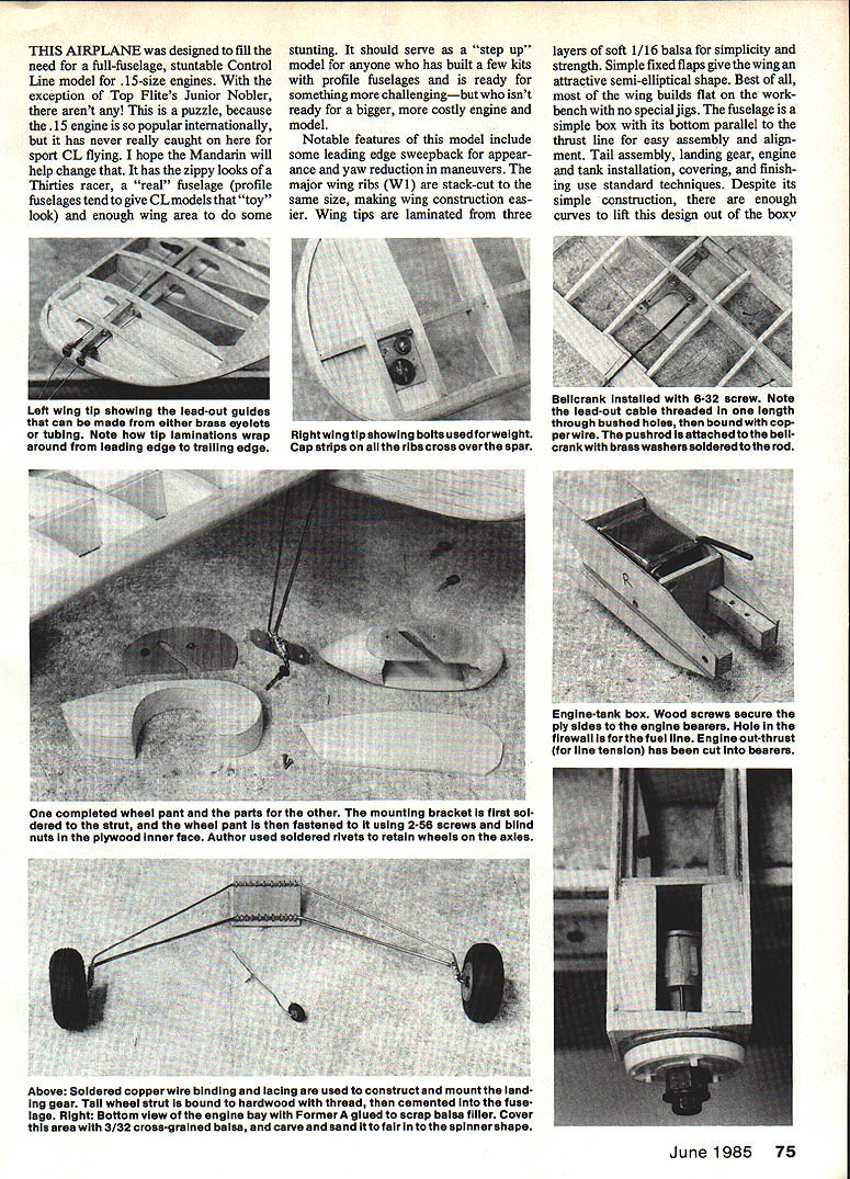
Make 1/16" plywood patterns for the ribs. Cut all ribs to shape, stack them together, and cut the spar notches with a thin hobby saw. With care, you can cut all the ribs from one sheet of 1/16" x 4" x 36" balsa. Alternatively, some builders use foam meat-tray plastic for ribs; it's about 1/16" thick, easy to cut, and less prone to shattering in a crash. If you use plastic ribs, the 1/16" cap strips are mandatory because the plastic won't tolerate much heat when shrinking covering.
Cut the spar webs oversize and trim them later for a good fit.
Before gluing, note that the left wing panel (the one on the inside of the flight circle) is 3/8" longer than the right panel. This compensates for the different lift characteristics between the inner and outer panels.
Cover the plans with Saran wrap. Crack both 3/16" spars at the proper dihedral angle and cement them at the angle shown. Pin the lower spar securely to the plan and block up the tip only about 1/8". Glue the W1 ribs to the lower spar, making sure they are parallel to the thrust line, standing straight up, and that the trailing edges of all ribs line up. Sight down the row and correct any misaligned ribs before gluing. Glue in the W2 ribs.
Trial-fit the top spar. Don't force it; open the spar notches in the ribs until the top spar fits easily and the rib tips still line up. Then glue the top spar. Hold the tips of the upper spar down about 1° in with large T-pins so the spar fits properly to the W2 ribs.
Installing the lower trailing edge can be tricky. First glue the two bottom pieces together using a 3/32" splice at the center, then make scrap wedges to hold the trailing edge lightly in place on the ribs without upsetting alignment. Glue on the lower trailing edge, but do not glue W2 to the trailing edge yet. Glue the top trailing edge, using plenty of glue at the splice.
Cut the spar webbing to fit and glue in place; these add considerable strength needed for high-stress maneuvers.
Check the wing for warps by stepping back and sighting forward from the trailing edge toward the spars. The trailing edge should follow the spars in parallel alignment across the span.
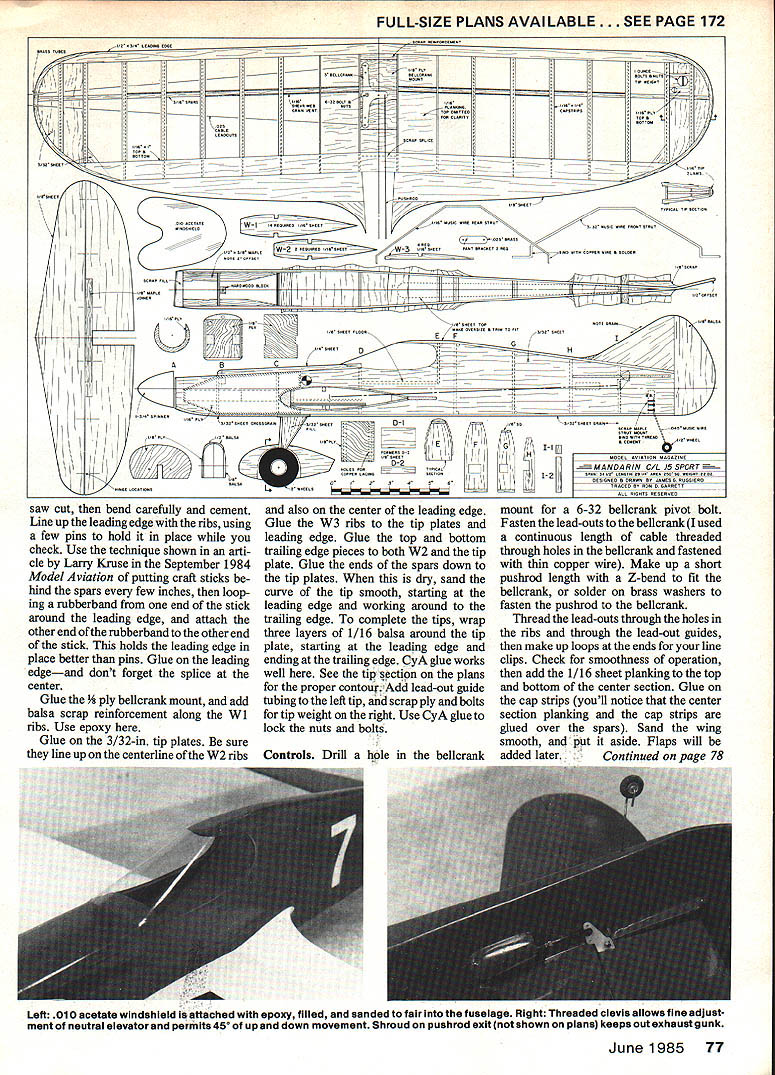
Remove the wing from the plan. Crack the leading edge at the center with a saw cut, then bend carefully and cement. Line up the leading edge with the ribs and use pins while checking alignment. A useful technique is to put craft sticks behind the spars every few inches, loop a rubber band from one end of the stick around the leading edge, and attach the other end of the rubber band to the other end of the stick. This holds the leading edge better than pins. Glue on the leading edge and remember the center splice.
Glue the 1/16" plywood bellcrank mount and add balsa-scrap reinforcement along the W1 ribs with epoxy.
Glue the 3/32" tip plates, making sure they line up on the centerline of the W2 ribs and on the center of the leading edge. Glue the W3 ribs to the tip plates and leading edge. Glue the top and bottom trailing-edge pieces to both W2 and the tip plate. Glue the ends of the spars down to the tip plates. When dry, sand the tip curve smooth, starting at the leading edge and working back to the trailing edge.
To complete the tips, wrap three layers of 1/16" balsa around the tip plate from leading edge to trailing edge, using CyA to bond. See the tip section on the plans for the proper contour. Add lead-out guide tubing to the left tip and scrap ply and bolts for tip weight on the right. Use CyA to lock the nuts and bolts.
Controls: drill a hole in the bellcrank mount for a 6-32 bellcrank pivot bolt. Fasten the lead-outs to the bellcrank (a continuous length of cable threaded through bellcrank holes and fastened with thin copper wire works well). Make up a short pushrod with a Z-bend to fit the bellcrank, or solder brass washers to fasten the pushrod to the bellcrank.
Thread the lead-outs through the holes in the ribs and through the lead-out guides, then make loops at the ends for your line clips. Check for smooth operation. Add the 1/16" sheet planking to the top and bottom of the center section. Glue on the cap strips (the center-section planking and cap strips are glued over the spars). Sand the wing smooth and set it aside. Flaps will be added later.
Engine and Tank Mount
The engine and tank mount is made as a box consisting of the engine bearer mounts and Formers B and C. Measure how much room you need for your fuel tank; you may need to move Former C back to accommodate a long tank (there is about 1/8" space between Former C and the wing as shown on the plans). If you want a removable tank, use a toothpick-and-screw hatch hold-down and some scrap fuel line tubing wedged between the tank and the fuselage sides.
Cut the two box sides from 1/16" plywood and mark the position of the engine bearers on each; these lines should be parallel to the bottom edges of the box sides. Make a right and a left side. Drill holes in the bearers for your engine, and be sure to include the outshaft thrust as shown on the plans. Insert 4-40 blind nuts, then epoxy the bearers to the sides; use wood screws too. Epoxy Formers B and C and check the tank fit. Drill holes for the fuel feed tubing through Former B and through an engine bearer for the tank vent.
Trial-fit the engine-tank box to the fuselage. Because the bottom of the box and the fuselage bottom are parallel to the thrust line, alignment should be easy. Epoxy the box in place and set the model aside.
Fuselage
Cut the fuselage sides and mark the inside for all formers and the engine and tank box. Draw a line on the outside of each fuselage side for the centerline of each flap so you can line them up later. Cut the pushrod exit in the right side. Slide the fuselage sides onto the wing for trial fit but don't glue yet.
Temporarily slide the stabilizer in place. Make any necessary bends in the clevis wire so it can exit smoothly from the fuselage, and temporarily fit the split sleeve over both the clevis wire and the short pushrod length from the wing. Ideally, with the pushrod and clevis ends touching, the clevis pin should just reach the hinge line of the stabilizer when the controls are neutral and the clevis is threaded about halfway onto the clevis wire. Make adjustments as needed, then solder the pushrod and clevis wire into the sleeve. Remove the clevis and slip a piece of fuel tubing over the threaded wire to protect it from glue and paint.
With the wing and stabilizer still temporary, set the fuselage on the workbench and glue Formers D through I, but don't glue the wing yet; you'll want to move the wing for perfect alignment when the fuselage is more rigid. Use masking tape while CA-gluing the upper fuselage sides to the curved portions of the formers.
Taper the inside ends of the fuselage sides to about 1/16" thickness at the rudder post, then glue the ends together. Remove the stabilizer. Make the 1/8" fuselage turtledeck a bit oversized (see dotted outline on the plan top view), score the inside where it bends over Former F, bend to fit, and glue it to the fuselage. Sand this to a smooth, round section.
Align the wing and fuselage, then epoxy thoroughly, working plenty of epoxy into the joints. Reinforce the inside of the wing-fuselage joint with fiberglass tape and scrap balsa. Be sure the left wing panel is 3/8" longer than the right one. Glue in the 1/8" cockpit floor.
Glue the fixed flaps in place, making sure the trailing edges are even and fair with the wing. Sand the fillets and fair the wing-to-fuselage joints smoothly.
Fill in the nose area with scrap 1/8" or 3/16" balsa. Temporarily install the engine and spinner to accurately locate Former A behind the spinner; there should be about 1/16" clearance between the spinner and Former A when the spinner is pushed back. Sand the scrap balsa until this clearance is achieved.
Use a soft pencil to outline Former A on the balsa, remove the engine, then epoxy Former A in place. When cured, true up the fuselage bottom of the engine bay with a sanding block or rasp, then epoxy 3/32" cross-grained balsa from the front of the landing gear mount to Former A. Use pins and tape to hold this piece in place. Carve and sand the lower nose to blend the flat fuselage area forward to a circular section at Former A.
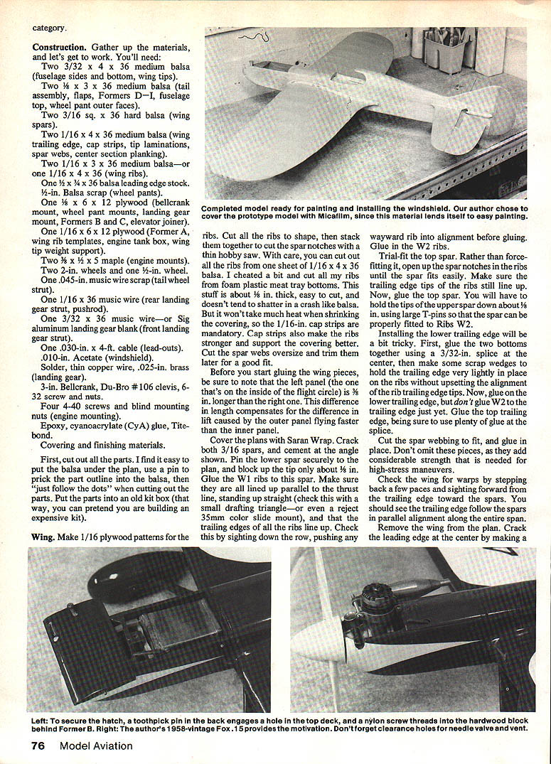
Cut a piece of 1/4" soft balsa for the top forward deck and the tank hatch. Mark the hatch, tack-cement the piece in place, and carve it to a round section. Using a razor saw, cut the hatch at Former C. Cement a blunted length of toothpick into the end of the hatch, blunt end out. Slide the hatch back so the toothpick makes a hole in the front of the top deck. Remove the hatch and reinforce the hole with a drop of CyA glue.
Temporarily install the tank. Make a hole in the fuselage bottom to clear the tank's overflow vent, and cut a hole in the underside of the engine bay to drain fuel residue.
Glue a small hardwood block to the back of Former B at the top. Push a pin through the hatch to locate the center of the block. Drill a 1/8" hole through the pinhole in the hatch only, then epoxy a short length of 1/4" birch dowel into the hatch. Drill a 1/16" hole through the center of the dowel and through the hardwood block. Tap the hole in the block for a 4-40 screw and use a 3/32" drill to open a clearance hole in the hatch. Make a clearance hole in the hatch for the tank filler and use a nylon screw to hold the hatch in place.
Landing Gear
Though the plans show a wire landing gear, you can also use a Sig aluminum landing-gear blank bolted to the landing-gear mounting plate. If you make a wire gear, sand the wire well to remove rust and scale before soldering. Use fine bare copper wire to bind the wire to the plywood and to bind wire ends for soldering. Solder the 0.025" brass part brackets to each strut; make bracket holes large enough to clear a 2-56 machine screw. Add 9/16" balsa fill between the struts.
Note: photos show a more forward-raked gear than the plans. The plans' arrangement uses less wire (less weight) and is less prone to ground looping.
Make the tailwheel strut from 0.045" music wire and bind it with thread to a piece of hardwood tapered to fit the rear fuselage. Reinforce the inside of the fuselage where the landing-gear plate will mount with scrap balsa for more gluing area, then epoxy the landing-gear plate in place. Epoxy the tailwheel bracket to the rear fuselage.
Install the landing gear and wheel pants (see wheel-pant mounting details on the plans). Fasten wheel-pant halves together and to the fuselage using 2-56 screws and blind nuts or soldered rivets.
Tail Assembly
If you use nylon hinges, cut the slots in the stabilizer, the 1/8" plywood or hardwood joiner, and each elevator half. Epoxy the hinges in the stabilizer, then epoxy the joiner to the hinges. When set, slide the stabilizer into the fuselage slot, line it up carefully, and epoxy it in place. Now epoxy the elevator halves to the joiner and hinges. Drill through each hinge tab and epoxy a short length of toothpick for locking pins. Add fillet pieces and a bead of epoxy mixed with microballoons at the stabilizer-fuselage joint.
Epoxy the fin to the fuselage top, ensuring the rear edge aligns with the rear end of the fuselage. Epoxy the rudder, offsetting it about 1/8" to the right. Run a bead of epoxy/microballoons on both sides of the fin-fuselage joint for strength and appearance.
Wheel Pants
If using standard-width wheels rather than thin racing wheels, the pants will be a bit chunky. Use two layers of 1/2" balsa for the inside and a layer of 1/8" balsa for the outer face. Cut the 1/8" ply inner face a bit larger than the plans show so you have plenty to carve away after assembly. Tack-cement the ply face to the pant and draw a pencil line around it onto the balsa. Slide the pant in place on the strut and spin the wheel to check for binding. Mark the bracket and transfer hole locations to the ply. Remove the ply, drill holes for 2-56 blind mounting nuts, then cement the ply permanently to the pant. Carve and sand the pants to shape and hollow them for lightness and wheel clearance. Be sure to make a true right and left pant—two identical ones are not correct.
Controls and Linkage
Drill holes and mount the elevator horn to the joiner with 2-56 screws and nuts. Remove the fuel tubing from the clevis wire, thread the clevis in place, and attach it to the elevator horn. Check controls for free movement. If the elevator hinges are sticky from paint, apply a drop of WD-40 to each hinge with a toothpick. For stunt flying, aim for about 45° of movement in both directions. Protect threaded clevis wire with a short length of fuel tubing when soldering.
Thread the lead-out cables through bushed holes in the wing tips and secure; brass eyelets or tubing may be used for lead-out guides. Install the bellcrank, solder the clevis to the pushrod as shown, and ensure the clevis pin reaches the hinge line of the stabilizer when controls are neutral.
Finishing Touches
Fill and sand any seams. Carve and sand the spinner from 3/32" cross-grained balsa to fair into the cowl. Finish the model with the covering and paint of your choice. Sand all wood areas well before brushing on filler. Ficafilm or similar covering works well for the wing if you want to spray the same colors as the rest of the model. Vinyl self-stick lettering is an easy option for markings—apply with a film of soapy water on the surface for positioning, then squeegee out the water.
Balance the model to the point shown on the plans or slightly forward, check control throws and linkage security, then test-fly.
With engine, prop, spinner, and tank in place, a typical finished Mandarin weighed about 22 oz dry. I made no attempt to select ultra-light balsa nor skimp on filler and paint; yours may weigh about the same or less.
Cockpit
Make a paper pattern of the windshield from the plans and customize it to fit your cockpit. Stick the pattern to the acetate with rubber cement, then cut the acetate a bit oversize with sharp scissors. Check fit and trim as needed, then peel off the pattern. Paint the inside of the cockpit as desired. Use bits of masking tape to hold the acetate in place on the model while you epoxily attach the windshield at points not covered by tape. Do not use CyA glue on the acetate; it will fog the surface. Test any alternative adhesives on scrap acetate first. Mask the windshield for final filler and paint operations.
Odds and Ends
- Thread the lead-outs and make secure loops for line clips.
- Protect threaded clevis wire with fuel tubing during soldering and finishing.
- Use plywood doublers where necessary to strengthen screw and landing-gear attach points.
- Drill the firewall hole for the fuel line before final engine installation.
- After final finishing, balance the model and recheck control throws and linkage security.
Flying
Use 52-ft lines and avoid flying near power lines. Check engine-out thrust and alignment, verify line tension, and ensure smooth control operation before attempting stunts.
Transcribed from original scans by AI. Minor OCR errors may remain.

