

Manhattan Pieces
By Walter P. Van Gorder
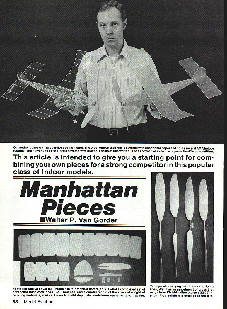
This article is intended to give you a starting point for combining your own pieces for a strong competitor in the popular Manhattan Cabin class of indoor rubber models. The Manhattan Cabin class is now in the AMA rule book, and I hope it becomes even more popular.
Background
We have Ed Whitten to thank for introducing Manhattan Cabin about 10 years ago. He was trying to create a class having a mixture of scale and pure duration concepts. I did not see a Manhattan Cabin model until 1977; I have been hooked ever since.
The original rules have held up very well, with only two changes to the time this was written. The model can now be covered with plastic film (but no microfilm); condenser paper was the only covering allowed by the original rules. The other change allows the use of a 12-in.-maximum-span stabilizer, which is a great improvement.
The model presented here, like most of my indoor models, is made up of pieces of various models I have tried. That's why it is named Manhattan Pieces. My first Manhattan was a copy of John Triolo's Skyscraper I; it was a bit heavy at five grams. My second model was a copy of Jim Miller's Cabin Fever. Then I started mixing parts and came up with another model which did much better.
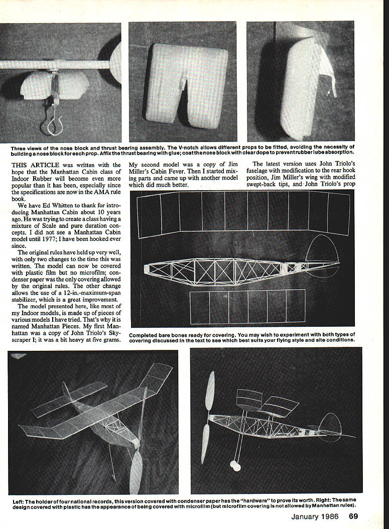
The latest version uses John Triolo's fuselage with modification to the rear-hook position, Jim Miller's wing with modified swept-back tips, and John Triolo's prop.
Manhattan Pieces holds AMA records in four ceiling categories with best times of 5:23 (Cat. I), 7:52 (Cat. II), 9:00 (Cat. III) touching a 65-ft. ceiling, and 9:37 (Cat. IV). The model has flights of 10:00 and 10:04 (West Baden) prior to establishment of AMA records for the class. I think the model has potential to fly 11 or 12 minutes.
Keep good records of wood sizes and weights when you build a model; they are a point of reference when building another or replacing broken parts.
Construction Overview
- The model is built to the four-gram minimum-weight rules.
- To cover the model with condenser paper you will have to use wood in the 5–6-lb. range.
- To cover the model with commercially available plastic you can use wood in the 7–8-lb. range; some plastics can be much heavier (about 50% heavier than condenser-paper-covered construction).
- Notes that refer to the condenser-paper-covered model apply to the record-holding model; the new plastic-covered model has not had enough testing to make a fair comparison.
One noticeable difference is that plastic-covered models fly much faster. I think the reason is that the covering is tighter, so the wing and stabilizer airfoils are truer. Condenser paper must be put on looser; therefore the airfoils are thicker. Rod Ganser, who also builds a lot of Manhattans, says his new plastic-covered models fly much faster. I think new plastic coverings will lead to experimentation with different airfoils.
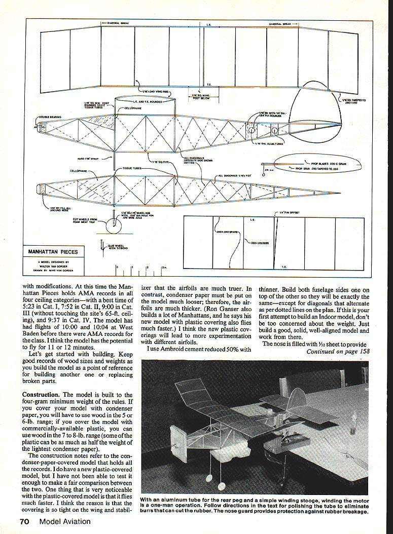
Use Ambroid cement thinned 50%. Build both fuselage sides and the top; other parts will be exactly the same except the diagonals alternate per the dotted lines on the plan. On your first attempt to build an indoor model, don't be too concerned about weight. Just build a good, solid, well-aligned model.
Work the nose filled with 1/32-in. sheet to provide strength for handling when connecting the fully-wound motor to the prop assembly. The rear motor supports are made of 1/16-in. sheet with a small 1/4-in. round piece of 1/8-in. plywood glued on the inside for added strength.
A little trick I use is to make sure the aluminum tubing used for the rear peg is highly polished — I use rubbing compound, but toothpaste will also work. Polishing removes even the slightest nicks in the tubing; a small nick in the rubber can result in premature failure. One other nice feature about the aluminum-tube rear motor peg is the fact you can put a .032 wire through it to hold the model in a winding stooge.
Build the rectangle part of the fuselage first. Crack the joints at the front and rear of the rectangle; glue the rear end together, and then put the nose together. You will end up with a very straight, true, well-aligned fuselage. When dry, lightly sand and set aside.
Prepare for building the wing, stabilizer, and upper and lower rudders by making a set of cardboard templates as shown in the pictures (soap cartons work well). Make sure the templates are undersize to allow for the spars. I use 1-in. squares of scrap cardboard to hold the spars against the template during construction.
Build up the wing exactly as the plan shows, keeping the spars straight and true. Use 1/16-in. leading and trailing edges with 1/32-in. sheeting where indicated. The ribs are notched to fit the spars and glued in place. The stabilizer is built the same way.
When assembling the tail, fit and glue the rudders and stabilizer in place, checking alignment carefully. Lightly sand all joints and fair in as required before covering.
Wing Structure and Materials
The wing structure and its construction are very simple. Use the following wood sizes and weights:
- Main spars: 8-lb., 1/16 x 1/16 sq.
- Ribs: 6 to 6-1/2-lb., 1/16 x .040 A- or C-grain
- Tip spars: 6-lb., 1/16 x 1/16 tapered to .050 x .050
After the wing is dry, sand the leading and trailing edges of the main flat section to an airfoil shape. Tip dihedral is 2-1/16 in.; use care and be exact. Make four 1-1/4-in. wing posts from 6-lb. balsa, and sand them round.
The stabilizer uses 6-lb. spars .050 x .040; ribs are 6-lb. .032 x .040 A- or C-grain. The airfoil is the same as the wing, except the rib is just cut off at the trailing edge. The rudder outline is made of 5-lb. .040 x .040 A-grain balsa.
Landing Gear
The landing gear must be sturdy enough to support the weight of the model.
- Strut: hard 1/16-in. sq. balsa.
- Wheels: cut from the bottom of a foam meat tray.
- A 1/16-in. sq. strip 1/4 in. long was drilled lengthwise with an .020-in. bit for a wheel bearing. If you do not have an .020-in. drill, glue small squares of 1/16-in. sheet balsa on each side of the wheel, and make a small hole through the squares (use white glue so the foam will not dissolve).
- A small piece of .015-in. wire glued to the strut acts as the axle.
This is the procedure for making the wing and landing gear sockets:
- Cut tissue strips about 3/8 x 2 in. long.
- Take a few drops of white glue and mix with a few drops of water. Lay a strip of tissue in the glue.
- Take a 1/16-in. drill bit, and roll the tissue around the smooth end.
- Very carefully slide the tissue tube off the drill bit, and place it on a piece of wax paper.
- Let it dry completely, then slide the tube back on the smooth end of the drill and cut into the required lengths.
Nose Block and Thrust Bearing
The nose block is made from one piece of 1/16-in. sheet. A plug cut to exactly fit the nose opening is made of 1/16-in. sheet. The grain should run perpendicular to the nose block grain for strength. Cut a V in the nose block as per the pictures, and use a standard thrust bearing for indoor models. By doing this, you can change the prop without having to make a new nose block for each prop. You may contour the nose block to get rid of the squared-off look. Give it a light coat of clear dope to keep rubber lube from soaking into the wood (which weakens it). Be sure to securely glue the thrust bearing.
Propellers
Propellers are a very important part of any indoor model, so take your time with them. To meet varying conditions, I fly with props ranging from 12 to 14 inches in diameter and pitches from 22 to 27 inches. A good general-purpose prop to start with is:
- 12-in. diameter, 3/4-in. blade width, 22-in. pitch
Procedure:
- Make a cardboard template of the blade, and cut two blades out of 6-lb. .025 C-grain balsa. Try to match the grain of the wood in each blade as closely as possible. Sand the blades just enough to round the edges a bit.
- Soak the blades in hot tap water for 15 minutes. Lay them on the prop form (a can, bottle, jar, or jug 6 to 8 in. diameter with smooth sides).
- Lay the wet blades on the form 15° to the left of center. Lash them to the form with a stretch gauze bandage just snug enough to hold them in place.
- Place in a preheated oven at 250°F for 15 to 20 minutes.
Prop spar and hub:
- Prop spar: 8-lb., 5/64-in. length sanded round to .093 in. at the center and tapering to .035 in. at the tips.
- Prop shaft: made from .015-in. wire bent to the shape shown on the plan. After the shaft is put into the center of the spar, bend the end at a 90° angle and glue with Hot Stuff.
Make a jig to assemble the blades to the hub so they are at 45° at 3.5 in. from the center of the hub. It is very important both blades be set exactly at the same angle, so take your time and do it right.
Covering and Finishing
If you use plastic for covering the model, be sure to cover the wood where the windshield and side windows go with black tissue (or use a black marking pen). If you use condenser paper, be sure to pre-shrink it. Condenser paper shrinks rather dramatically when exposed to heat; this can be countered by covering the model in a high-temperature environment, such as a high-temperature, low-humidity box (I built one with a desiccator for drying).
- Place the part to be covered with condenser paper into the box for a half-hour to remove excess moisture.
- When you are ready for covering, raise the plastic about halfway so you can get inside to do the work.
I used thinned Micro-X condenser paper cement to adhere the covering. It works great on condenser paper or plastic film. When you remove the covered part from the high-temperature, low-humidity box, the condenser paper will get limp. Since you seldom fly in humidity less than 20–30% or temperatures exceeding 90–100°F, your model should not warp because of condenser paper shrinkage.
After covering, balance and trim the model for the flying site and motor run you intend to use.
Final Assembly
- Glue the tissue wing sockets into the fuselage, then put the wing into these sockets. Glue the wing to the fuselage with the nose blocked square.
- Offset the wing 1/8 in. to the left when viewing from the rear of the model — this makes the wing panel 1/4 in. longer on the inside of the left-hand circle.
- Glue the stabilizer on the fuselage, making sure the trailing edge is 3/32 in. higher than the leading edge.
- Glue on the rudder with 1/4 in. offset for turn.
- Glue on the subrudder in the center.
- Glue a 5/32-in. shim on the right side of the fuselage nose to get left thrust.
- Glue the tissue landing gear sockets on the fuselage.
Test Flying and Trim
Start out using a 25-in. loop of .085 rubber (the rubber I use is from FAI Model Supply). Put about 50 turns in the motor, and launch the model by hand. It should fly to the left in circles of 25–30-ft. diameter. As you add more turns to the rubber (and torque), you will have to put in about 1/8 in. of wash-in on the left wing panel. I also use about 3/32 in. of wash-in on the left side of the stabilizer.
For best results, trim the model to fly just on the edge of a stall on full-power takeoffs. The center of gravity (CG) should be as far rearward on the model as it will take and still have stable flight. To adjust the CG, I put a dab of clay on the back of the fuselage.
How much duration you get will depend upon how familiar you become with the model. With experimentation, you will soon find the combination of prop and rubber that is just right for your model.
Suppliers for Indoor Models
- Jim Jones, 36631 Ledgestone, Mt. Clemens, MI 48043
- Indoor Model Supply, P.O. Box 39, Garberville, CA 95440
- Micro-X Products, Inc., P.O. Box 1063, Lorain, OH 44055
- Ray Harlan, 15 Happy Hollow Rd., Wayland, MA 01778
Contact
I will be glad to answer any other questions you might have. Send a stamped, pre-addressed envelope to:
Walter P. Van Gorder 5669 Victoryview Ln. Cincinnati, OH 45238
or call (513) 292-3351.
Transcribed from original scans by AI. Minor OCR errors may remain.

