
Editor's Note
We are pleased and proud to publish this excellent free-flight design. Its story began in 1972–73 when the pictures and plans were prepared—and a special challenge led to its publication. After reading this introduction you'll agree that Tom made all his points. What he goes on to say about construction and flight adjustments belong in any pro/free-flighter's scrap book.
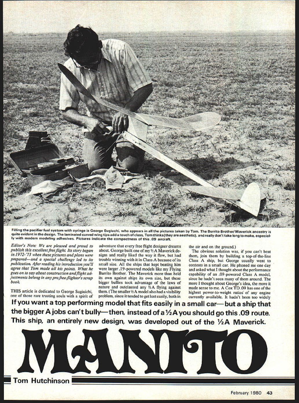
This article is dedicated to George Sugiuchi, one of those rare trusting souls with a spirit of adventure that every free-flight designer dreams about.
George built one of my 1/2A Maverick designs and liked the way it flew, but had trouble winning with it in Class A because of its small size. All the ships that kept beating him were larger .19-powered models like my Flying Burrito Brother. The Maverick more than held its own against ships its own size, but these bigger jobs took advantage of the laws of nature and outclassed any 1/2A flying against them. The smaller 1/2A model also had a visibility problem, since it tended to get lost easily, both in the air and on the ground.
The obvious solution was: if you can't beat them, join them—build a top-of-the-line Class A ship. George usually went to contests in a small car, so he wondered about the performance capability of an .09-powered Class A model, since he hadn't seen many of them around. A Cox TD .09 has one of the highest power-to-weight ratios of any engine currently available. It hadn't been widely used because it can't readily be switched to fly two classes in the same model. A model built strictly for Class A competition with this engine would be potent because of its larger size and higher power, yet still compact enough to fit into a small car.
Since George liked the way the Maverick flew, the new design was based on its proportions as much as possible. I made some quick calculations and phoned back the dimensions. The next day George showed up with a complete set of working drawings for approval. Within two weeks the first prototype was completed and ready for test flights. George reported back his enthusiasm the day after the initial flights—the ship flew right off the board with the same good flight characteristics. He started another immediately as a backup model.
Bob Ohly accompanied George to the early testing sessions. Subsequent fliers wanted to build models too and asked George to borrow a set of working drawings; he decided to make up a set and ink the plans. After seeing the ship, we thought we might have come up with a good-flying airplane: a distinctive concept, a well-drawn set of plans, and an experienced author to write the text. The name came easily enough: "Manito," East L.A. Spanish for "little brother," felt appropriate considering its Burrito Brother/Maverick ancestry.
I took some photos at George's Lake Elsinore flying session and began preparing an article in the spring of 1973. A rough draft was half-completed when I came back from vacation to learn the shocking news—George died of a sudden heart attack. Since he had provided much inspiration for the project, I put away the plans, photos and rough draft.
After getting married, starting a new career in teaching, and moving several times, I had almost forgotten about Manito until last fall. The editor asked if I had any good free-flight designs suitable for publication that weren't "just another look-alike." That jogged my memory; I pulled the Manito plans out of the attic to see if they would meet the stringent requirements. After six years, Manito still looked like a good idea. Flying fields and engine runways haven't changed; automobiles have shrunk. A compact Class A model with better-than-1/2A performance should still be attractive to fliers. The editor agreed, and Manito now appears in print just as George and Bob envisioned.
If you want a top-performing model that fits easily in a small car—but that the bigger A jobs can't bully—then, instead of a 1/2A, consider this .09 route.
Manito
Tom Hutchinson
The Manito is an entirely new design developed out of the 1/2A Maverick, scaled and adapted to take advantage of the Cox TD .09's high power-to-weight ratio and to remain compact for transport.
Powerplant and Weight
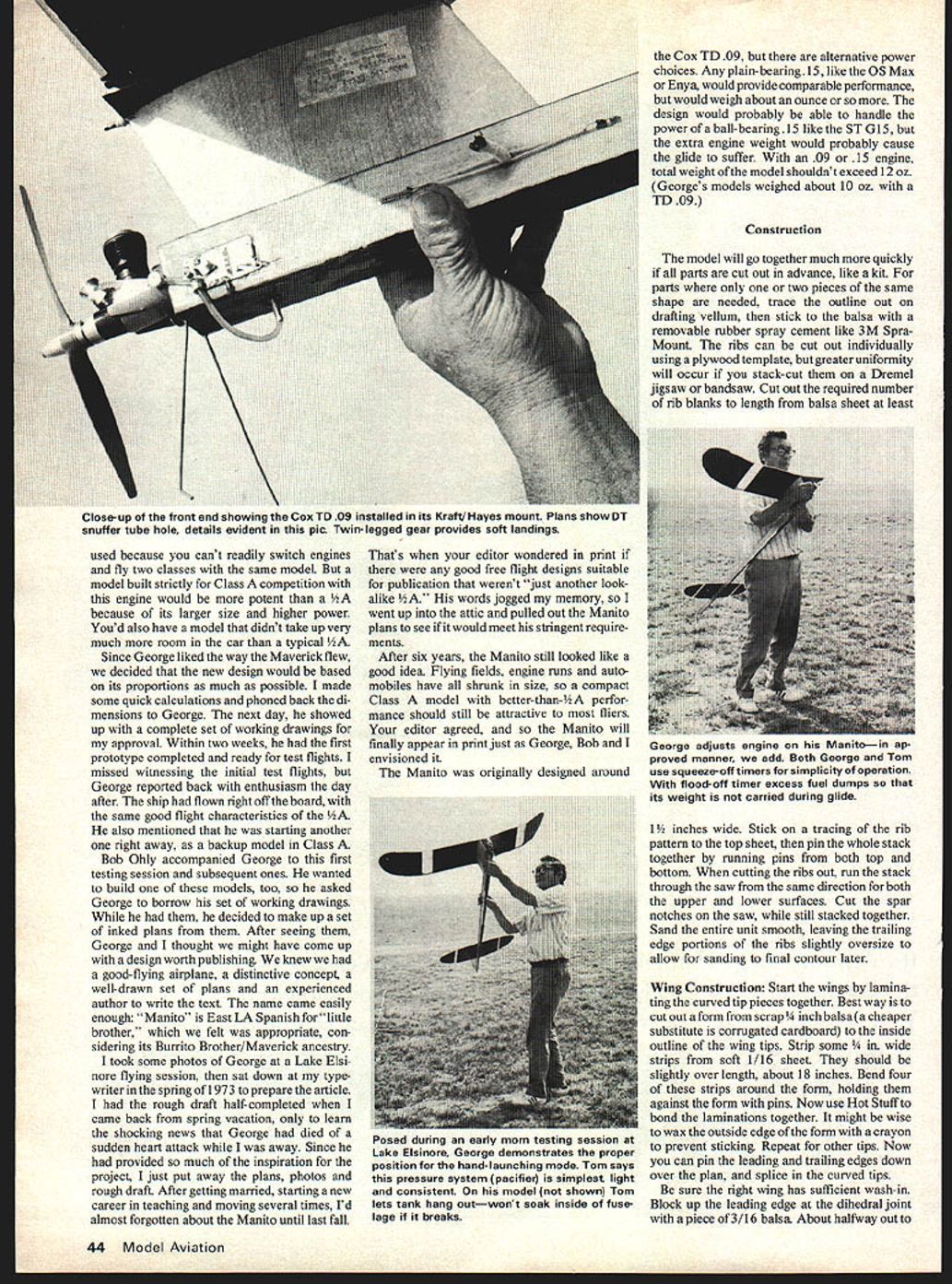
- Designed originally around the Cox TD .09.
- Alternative power choices:
- Any plain-bearing .15 (for example, OS Max or Enya) will provide comparable performance but will weigh about an ounce more.
- A ball-bearing .15 (for example, ST G15) might be handled by the design, but the extra engine weight would likely hurt the glide.
- With an .09 or .15 engine, total model weight should not exceed about 12 oz. (George's models weighed about 10 oz. with a TD .09.)
Construction
The model will go together much more quickly if all parts are cut out in advance, much like a kit. For parts where only one or two pieces of the same shape are needed, trace the outline on drafting vellum, then stick the tracing to the balsa with a removable rubber spray cement such as 3M Spray-Mount.
Ribs:
- Ribs can be cut individually using a plywood template, but greater uniformity results from stack-cutting on a Dremel jigsaw or bandsaw.
- Cut the required number of rib blanks to length from balsa sheet at least 1-1/2 inches wide.
- Stick on the rib tracing to the top sheet, then pin the whole stack together by running pins from both top and bottom.
- When cutting ribs, run the stack through the saw from the same direction for both upper and lower surfaces.
- Cut spar notches on the saw while the stack is together.
- Sand the unit smooth, leaving trailing-edge portions of the ribs slightly oversize to allow final sanding to contour later.
Use Hot Stuff or a similar quick CA for many assembly joints; use 5-minute epoxy for dihedral joints (it doesn't warp, fills gaps, and dries fast enough to allow both center and tip joints to be made in one night).
Wing Construction
- Tip laminations:
- Cut a form from scrap 1/4-inch balsa (or corrugated cardboard) to the inside outline of the wing tips.
- Strip 1/16-inch sheet into 1/4-inch wide strips, slightly overlength (about 18 inches).
- Bend four strips around the form, holding with pins, and bond the laminations with Hot Stuff.
- Wax the outside edge of the form with a crayon to prevent sticking. Repeat for the other tip.
- Assembly:
- Pin the leading and trailing edges down over the plan and splice in the curved tips.
- Ensure the right wing has sufficient wash-in.
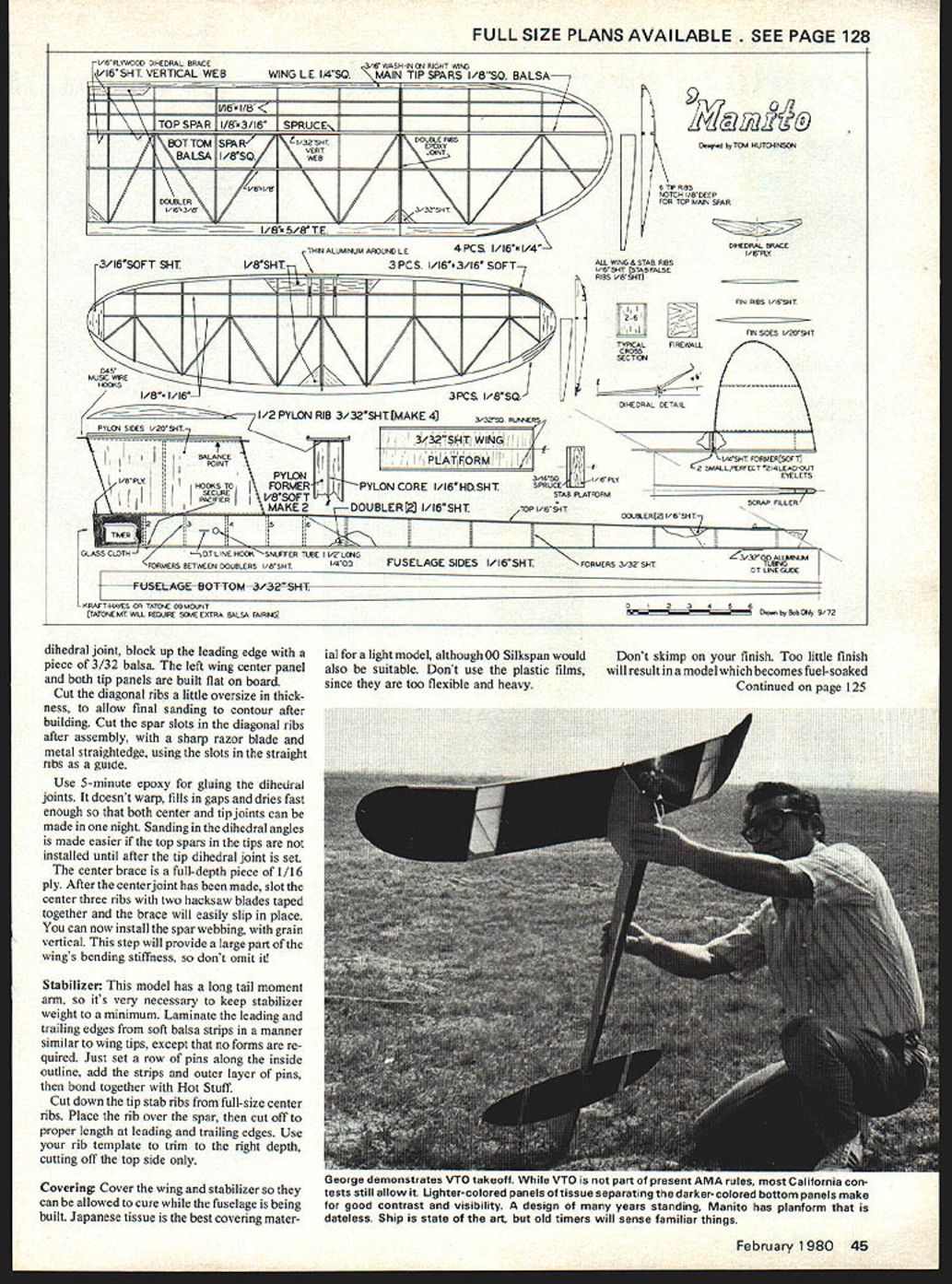
- Block up the leading edge at the dihedral joint with 3/16-inch balsa. About halfway out to the dihedral joint, block up the leading edge with 3/32-inch balsa.
- The left wing center panel and both tip panels are built flat on the board.
- Diagonal ribs and spars:
- Cut diagonal ribs a little oversize in thickness to allow final sanding to contour after building.
- Cut the spar slots in the diagonal ribs after assembly with a sharp razor blade and metal straightedge, using slots in the straight ribs as a guide.
- Install spar webbing with grain vertical—this provides a large part of the wing's bending stiffness; don't omit it.
- Dihedral joints:
- Use 5-minute epoxy for the dihedral joints.
- Sanding in the dihedral angles is easier if the top spars in the tips are not installed until after the tip dihedral joint is set.
- The center brace is a full-depth piece of 1/16-inch plywood. After the center joint is made, slot the center three ribs with two hacksaw blades taped together and slip the brace in place.
Stabilizer
- Keep stabilizer weight to a minimum due to the long tail moment arm.
- Laminate the leading and trailing edges from soft balsa strips similar to the wing tips—no forms required. Pin along the inside outline and bond the layers with Hot Stuff.
- Cut down the tip stab ribs from full-size center ribs: place the rib over the spar, cut to proper length at leading and trailing edges, then trim the top side only to the correct depth using your rib template.
Covering
- Cover wing and stabilizer before building the fuselage so they can cure while the fuselage is built.
- Japanese tissue is the best covering material for a light model; 00 Silkspan is an acceptable alternative.
- Do not use plastic films—they are too flexible and heavy for this design.
Don't skimp on finish. Too little finish will result in a model that becomes fuel-soaked quickly, shortening its useful lifetime. Use about three coats of nitrate dope with a clear epoxy final coat. Give a couple of extra coats to the front portion of the stabilizer, since exhaust residue tends to collect there.
Fuselage
- Shell and formers:
- Use a metal straightedge to cut out the sides, then add nose and tail doublers.
- Draw the top view on 3/32-inch sheet but don't cut it out yet.
- Pin the bottom to the building board and glue in formers (Hot Stuff works well).
- Add the sides, checking carefully for alignment, then sand the fuselage assembly and add the top.
- Pylon:
- Build the pylon by gluing the pylon core to bottom rails, add formers checking that the core is truly vertical, add top ribs, sand, and cover with 1/20-inch sheet.
- Fin:
- Build the fin similarly: cut two sides to the outline, glue the fin ribs to one side with Hot Stuff, sand flush, then glue on the other side. No central cowl is needed.
Finish recommendation:
- Use an epoxy finish such as Hobbypoxy on the fuselage; high-nitro fuels will destroy many other finishes quickly.
- Cover the fuselage with tissue using nitrate dope for better adhesion.
- Apply a couple of coats of thinned nitrate lacquer sanding sealer, then two coats of colored epoxy (add an extra coat of epoxy at the front end).
- Wet sand the first epoxy coat with #400 wet-or-dry sandpaper and the final coat with #600. Rub out with Dupont white polishing compound.
Assembly:
- Assemble the complete model and move the pylon until the ship balances where indicated (or very slightly forward), then epoxy it in place.
Flying and Trimming
Before going to the field, assemble the model and check thoroughly for proper balance and correct warps. The center of gravity (CG) should be where shown on the plans. If the model balances tail-heavy, move the engine forward by inserting additional plywood spacers between the firewall and the engine mount. The engine should point straight ahead, or slightly left.
Hand-glide the model to check for stalling or diving tendencies. Correct by shimming the front or back of the stabilizer with thin ply pieces. There should be a definite glide circle to the right. Run the engine a few times to familiarize yourself with the pacifier fuel system and to make sure the engine will pick up from a glide.
Preliminary checks and first flights:
- First short run:
- For the first flight, try a 5-second run with the prop on backwards and the engine at full bore. This helps get rid of first-flight jitters and checks general behavior.
- If the model does anything but climb straight out at a shallow angle, you may have problems. A sharp right turn may indicate a misaligned rudder or bent fuselage. A steep climb at this stage means too much incidence.
- Full-power trimming:
- From now on, all flights should be made at full power with the prop in the proper direction. Free-flight trim depends on being set for one speed; adjustments are delicate balances between power and climb at the proper speed.
- Try a full-power test flight with about a 3-second engine run. The model should climb straight out at a steep angle.
- Adjust thrust offset to correct any turning tendencies right at launch.
- Remove incidence if the model loops on this short run. If it has a shallow climb angle or the nose tucks under, add incidence by shimming the rear of the stabilizer.
- When it climbs straight with no looping on a 3-second run, increase the engine run in 2-second increments.
- Rudder tab adjustments:
- If the model tends to go left on longer engine runs, add a right rudder tab. Use pieces of 1/16 x 3/16-inch balsa cut to a trailing-edge section and glue to the appropriate side of the rudder. Vary the tab length to get more or less effect.
- The thick, built-up rudder section makes the model fairly insensitive to rudder tab adjustments, making fine-tuning easier.
Trim philosophy and desired pattern:
- The trim method is similar to that used on FAI power models to obtain a right/left pattern, but without auto-surfaces.
- Thrust adjustments are most effective at low speeds (the first few seconds after launch). Wing wash-in gives a left roll tendency during the right climb; the rudder tab corrects later stages of the power pattern.
- You'll probably end up with a slight amount of left thrust plus some right rudder tab (if warps are correct).
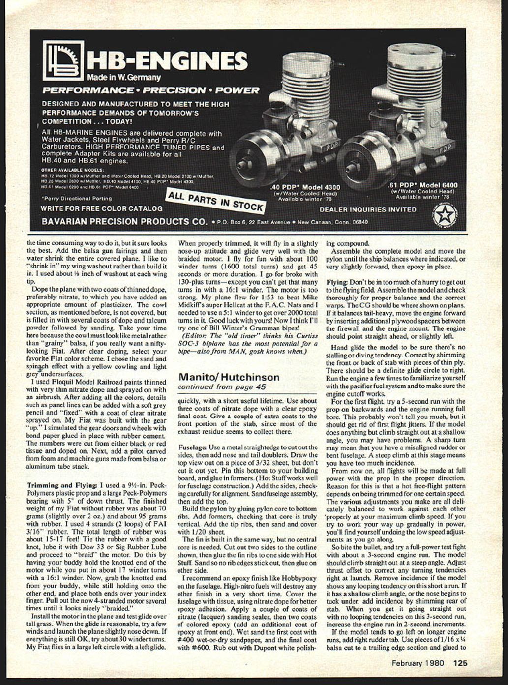
Desired power pattern:
- A straight climb for about three seconds, gradually changing into a right climb, making about one complete turn in nine seconds.
- If the model makes too many turns ("round and round"), reduce incidence to straighten and speed the climb.
- If the model climbs too straight up and then tends to go left at the end of the power pattern, add more right rudder tab.
- If it stalls and doesn't recover quickly when the engine cuts, add more incidence.
Glide trimming:
- After setting the power pattern, check the glide again.
- Add weight to the rear of the fuselage until the model stalls slightly in the glide, then remove a bit.
- Do not tilt the stabilizer to change the glide circle—this will affect incidence and may upset the trimmed power pattern. Instead, add shims to the wing rails and tilt the wing.
- The glide circle should be about one complete circle in 40 seconds in calm weather; tighten to about 30 seconds if the wind increases.
Final note: Careful construction, finish, and methodical trimming will yield a compact Class A model with competitive performance and excellent transportability—precisely what George and his friends wanted when they developed Manito.
Transcribed from original scans by AI. Minor OCR errors may remain.

