
Mariah
Introduction
Last month we presented an introduction to slope soaring that gave the generalities of what the sport is all about and some examples of models suited for this activity. This month we get down to specifics with this nifty little ship that can take full advantage of even the lightest winds yet still deliver aerobatic performance.
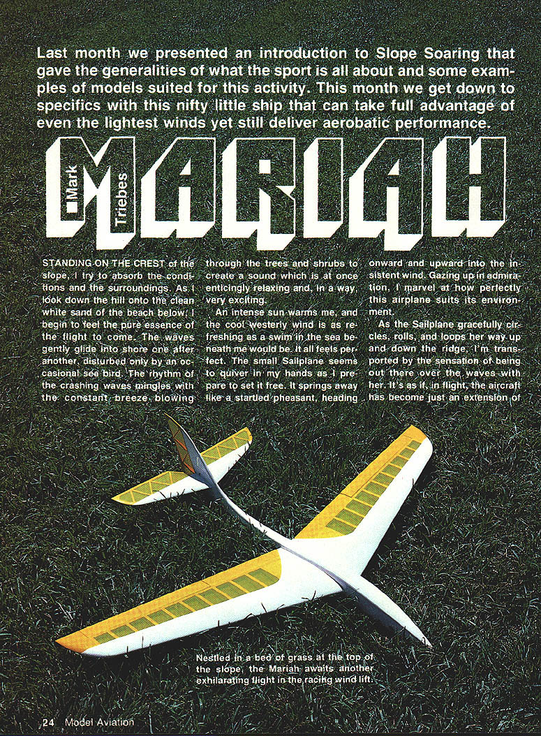
Standing on the crest of the slope, I try to absorb the conditions and the surroundings. As I look down the hill onto the clean white sand of the beach below, I begin to feel the pure essence of the flight to come. The waves gently glide into shore one after another, disturbed only by an occasional sea bird. The rhythm of the crashing waves mingles with the constant breeze blowing through the trees and shrubs to create a sound which is at once enticingly relaxing and, in a way, very exciting.
An intense sun warms me, and the cool westerly wind is as refreshing as a swim in the sea beneath me would be. It all feels perfect.
The small sailplane seems to quiver in my hands as I prepare to set it free. It springs away like a startled pheasant, heading onward and upward into the insistent wind. Gazing up in admiration, I marvel at how perfectly this airplane suits its environment.
As the sailplane gracefully circles, rolls, and loops her way up and down the ridge, I'm transported by the sensation of being out there over the waves with her. It's as if, in flight, the aircraft has become just an extension of me. What started life as a mere bundle of sticks and sheeting now seems to be virtually a part of me. It's a heady illusion, and I surrender to it gladly. The sense of freedom that it brings is like no other, and I realize that through no other act can I achieve such a feeling.
While the idyllic scene I've just pictured has been experienced by many sailplane fliers, it's relatively rare that every detail falls so perfectly into place. Most sailplanes require at least moderate winds in order to fly. How many times have you taken your ship to the slopes, only to find that you have to wait an hour or two for the wind to really start blowing—or that the wind never blows more than about five or ten knots? I've encountered both these conditions on many occasions, and have either resorted to flying a "floater" or not flown at all.
Floaters can be relatively amusing, but I can only stand so much S-turning back and forth. What I wanted was some type of sailplane that was highly maneuverable and aerobatic, but that could also fly in very light winds. I wanted a ship with the fun quotient not dependent on a gale force. Obviously, such a plane would have to be small, lightweight, and agile.
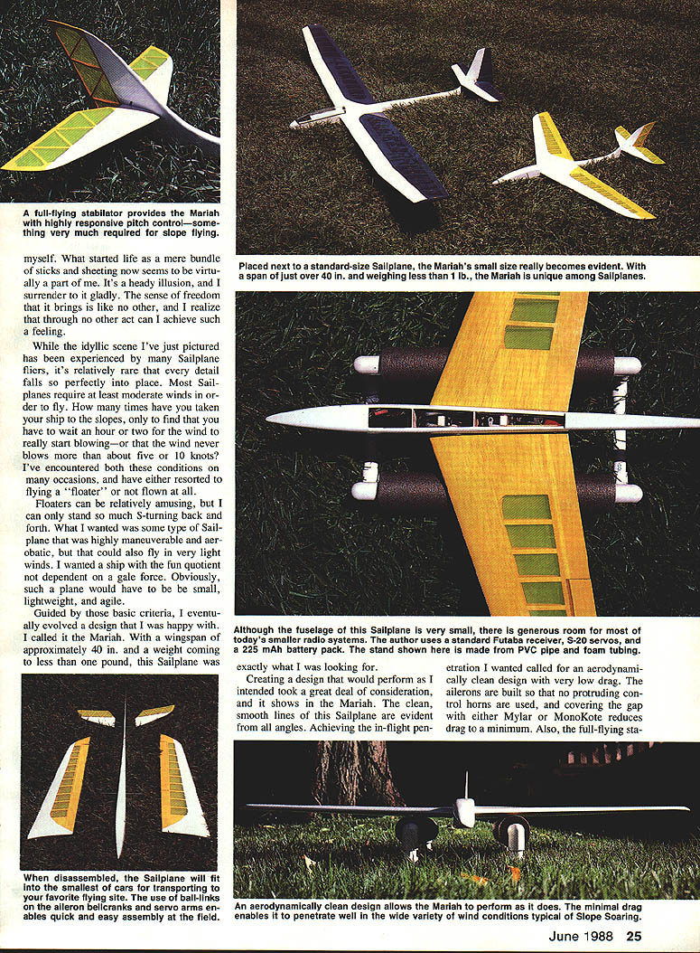
Guided by those basic criteria, I eventually evolved a design that I was happy with. I called it the Mariah. With a wingspan of approximately 40 in. and a weight coming to less than one pound, this sailplane was exactly what I was looking for.
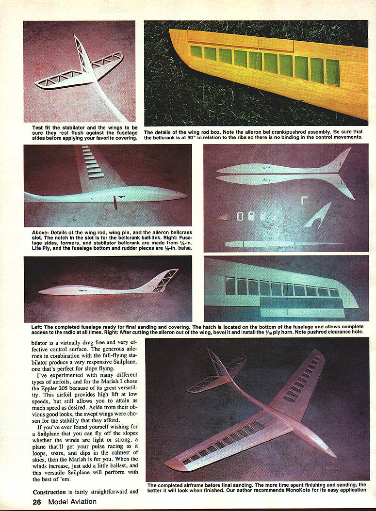
Creating a design that would perform as I intended took a great deal of consideration, and it shows in the Mariah. The clean, smooth lines of this sailplane are evident from all angles. Achieving the in-flight penetration I wanted called for an aerodynamically clean design with very low drag. The ailerons are built so that no protruding control horns are used, and covering the gap with either Mylar or MonoKote reduces drag to a minimum. Also, the full-flying stabilator provides the Mariah with highly responsive pitch control—something very much required for slope flying.
Although the fuselage of this sailplane is very small, there is generous room for most of today's smaller radio systems. The author uses a standard Futaba receiver, S-20 servos, and a 225 mAh battery pack.
I've experimented with different types of airfoils. The Mariah uses the Eppler 205 because of its great versatility. This airfoil provides high lift at low speeds yet still allows the airplane to attain much speed when desired. The swept wings were chosen for the stability they afford.
If you've ever found yourself wishing your sailplane could fly off the slope whether the winds were light or strong, and that it would get your pulse racing with loops, soars, and dips in the calmest skies, the Mariah will do just that. As the winds increase, just add a little ballast—this versatile sailplane will perform well.
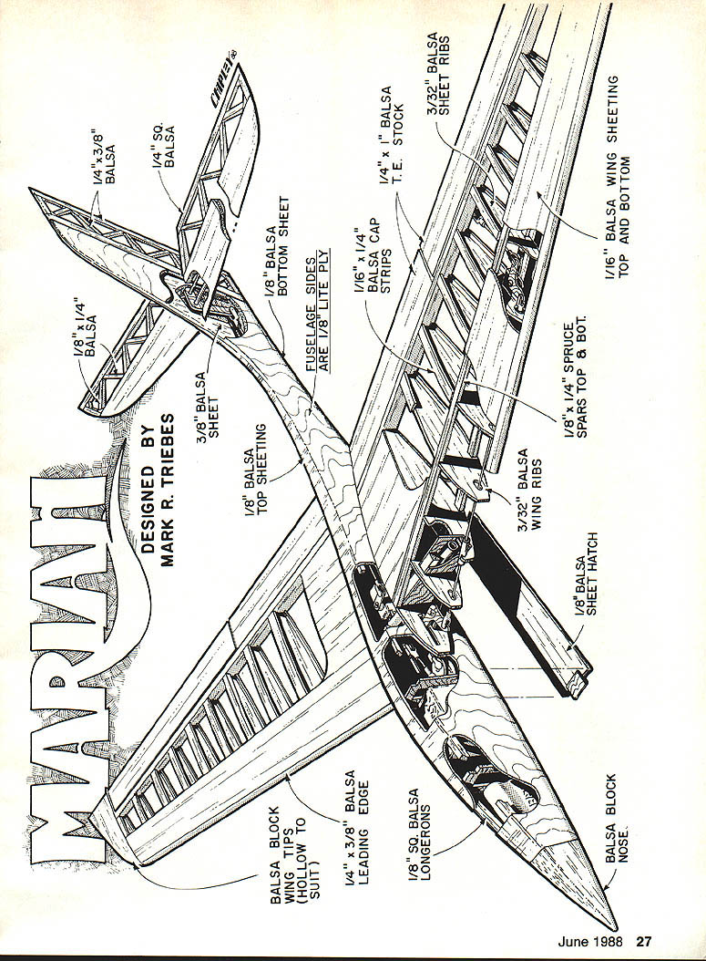
Construction is fairly straightforward and the simple fuselage is built of lite ply and balsa.
Designed by Mark R. Triebes
Materials
- Balsa block wing tips (hollow to suit)
- 1/4 x 3/8 in. balsa trailing edge
- 1/8 x 1/4 in. balsa cap strips
- 1/4 x 1/4 in. balsa T.E. stock
- 3/32 in. balsa wing ribs
- 1/8 x 1/4 in. spruce spars, top & bottom
- 1/16 in. balsa wing sheeting, top and bottom
- 1/8 in. balsa top sheeting
- 1/8 in. balsa bottom sheeting
- 1/8 in. balsa sheet hatch
- Balsa block nose
- Fuselage sides: 1/8 in. lite ply
- 1/8 in. sq. balsa longerons
- 1/8 in. x 3/8 in. balsa leading edge (see text)
- 1/16 in. plywood root rib
- 1/8 in. x 1/4 in. spruce hatch retainer pieces
- 1/8 in. O.D. brass tubing, various small pieces
- 1/8 in. music wire, 3/32 in. music wire, 7/32 in. drill for wing pin holes
- Epoxy, white glue (Titebond), microballoons, MonoKote or Mylar
Building tips and general advice
- Use clear plastic sheeting (plastic wrap or MonoKote backing) over the plans to preserve them and ensure a clean build.
- Use white glue (Titebond) for most of the work and a good epoxy where specified.
- Use lite ply for fuselage sides, stabilator roots, and inner wing ribs; spruce for spars; contest-grade balsa for the remainder.
- Label all parts—especially wing ribs and fuselage formers—to avoid confusion.
- Read the article and study the plans before starting to familiarize yourself with the design and construction sequence.
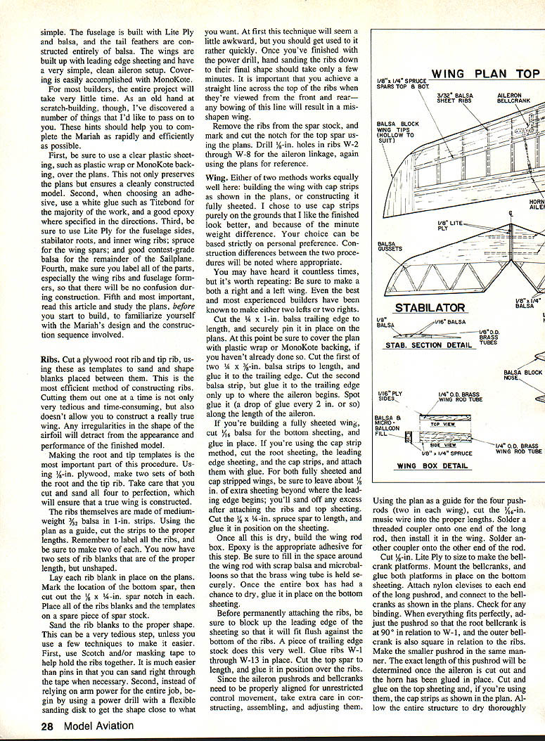
Ribs
- Cut a plywood root rib and tip rib and use them as templates to sand and shape balsa blanks placed between them. This template method produces a more accurate, true wing than cutting ribs one at a time.
- Make two sets of root and tip templates from 1/8-in. plywood (four templates total). Sand them to perfection so a true wing results.
- The ribs themselves are made of medium-weight 3/32-in. balsa in 1-in. strips. Cut the strips to proper lengths and label each rib; make two of each.
- Lay each rib blank on the plans, mark the bottom spar location, and cut the 1/8 x 1/4-in. spar notch in each rib.
- Place all rib blanks and templates on a scrap board and sand to shape. Use Scotch or masking tape to hold ribs together while sanding.
- Use a power drill with a flexible sanding disk to rough-shape the ribs, then finish by hand. Ensure a straight line across the top of the ribs when viewed from the front and rear—any bowing will distort the wing.
- Remove ribs from the spar stock, then mark and cut the notch for the top spar. Drill 1/16-in. holes in ribs W-2 through W-8 for the aileron linkage per the plans.
Wing
- Two accepted methods: cap-strip construction (as shown on plans) or fully sheeted wing. Cap strips save a little weight and look nicer to some builders; choice is personal.
- Make both a right and a left wing—don’t build two of the same.
- Cut the 1/4 x 1-in. balsa trailing edge to length and pin in place on the plans. Cover the plans with plastic wrap or MonoKote backing first.
- Glue the first 1/4 x 3/8-in. balsa strip to the trailing edge. Cut the second strip but glue it only up to where the aileron begins; spot-glue along aileron area (a drop every ~2 in.).
- If fully sheeting, cut 1/16-in. balsa bottom sheeting and glue in place. If using cap strips, cut root sheeting, leading edge sheeting, and cap strips and attach them.
- Leave about 1/8 in. of extra sheeting beyond the leading edge start; sand off excess after ribs and top sheeting are attached.
- Cut the 1/8 x 1/4-in. spruce spar to length and glue it in position on the sheeting.
- Build the wing rod box using epoxy. Fill around the brass wing tube with scrap balsa and microballoons so the brass wing tube is held securely. Allow to dry, then glue the box in place on the bottom sheeting.
- Before permanently attaching ribs, block up the leading edge sheeting so it fits flush against the bottom of the ribs (a piece of trailing edge stock works well). Glue ribs W-1 through W-13 in place, then cut and glue the top spar over the ribs.
- Aileron pushrods and bellcranks need careful alignment. Using the plan for the four pushrods (two in each wing), cut 1/16-in. music wire to length. Solder a threaded coupler onto one end of the long rods and install in the wing; solder a coupler onto the other end.
- Cut 1/8-in. lite ply for bellcrank platforms, mount bellcranks and glue platforms in place on the bottom sheeting. Attach nylon clevises to each end of the long pushrod and connect to bellcranks. Check for binding. Adjust bellcranks so the root bellcrank is at 90° in relation to W-1 and the outer bellcrank is square in relation to the ribs.
- Make the smaller pushrod similarly; its final length is set after cutting the aileron and gluing the horn.
- Cut and glue on top sheeting and cap strips (if used). Allow center structure to dry thoroughly before sanding the wing.
- Sand the wing carefully—use a long, flat sanding block (e.g., 24 x 4 in.) to avoid flat spots or irregularities. Sand the two 1/4 x 3/8-in. strips to the proper airfoil shape.
- Sand the wing tip flat, cut balsa wing tip to shape, and glue onto the wing, spot-gluing at the aileron. Sand off excess sheeting at the leading edge and glue the 1/8 x 3/8-in. balsa leading edge in place.
- Sand the root of the wing flat and glue on the 1/16 plywood root rib.
- Final shape and sanding with the long sanding block will produce a smooth, evenly contoured wing.
- Cut out the aileron per the plans, bevel it for movement, and drill the 1/4-in. hole in the wing trailing edge for the pushrod. Make the control horn, temporarily slide it into the aileron slot, place the aileron in position, adjust the small pushrod so bellcrank and aileron are neutral, and glue the horn in place.
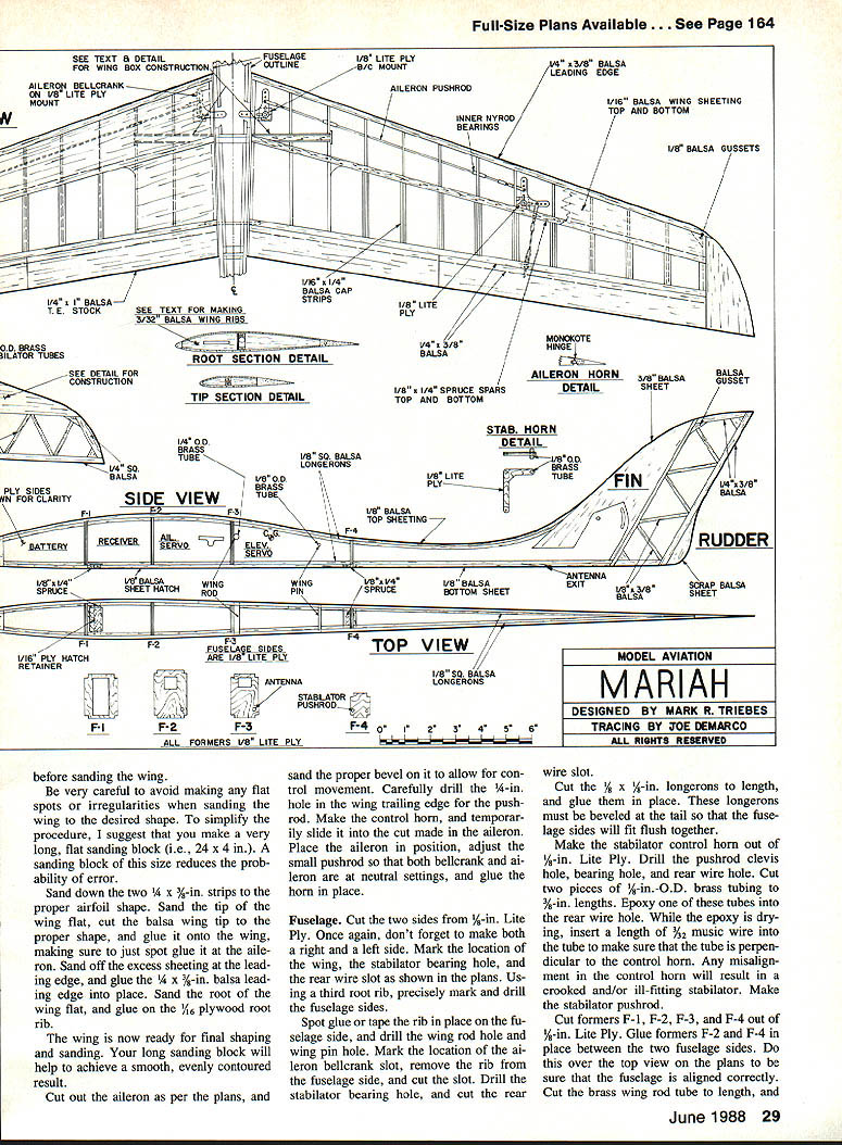
Fuselage
- Cut two sides from 1/8-in. lite ply—make a right and a left side. Mark wing location, stabilator bearing hole, and rear wire slot per the plans.
- Using a third root rib as a template, precisely mark and drill the fuselage sides. Spot-glue or tape the rib in place on the fuselage side and drill the wing root hole and wing pin hole. Mark and cut the aileron bellcrank slot, drill stabilator bearing hole, and cut the rear wire slot.
- Cut 1/8 x 3/8-in. longerons to length and glue in place. Bevel longerons at the tail so fuselage sides fit flush together.
- Make the stabilator control horn from 1/8-in. lite ply. Drill the pushrod clevis hole, bearing hole, and rear wire hole. Cut two pieces of 1/8-in.-O.D. brass tubing to 3/8-in.; epoxy one into the rear wire hole. Insert 3/32 music wire into the tube while epoxy dries to ensure perpendicular alignment—misalignment leads to a crooked stabilator. Make the stabilator pushrod.
- Cut formers F-1 through F-4 from 1/8-in. lite ply. Glue F-2 and F-4 in place between fuselage sides over the top view on the plans to ensure correct alignment.
- Cut the brass wing rod tube to length and glue it in place. Glue in former F-3 so it is flush against the brass tube. Allow to dry thoroughly.
- Position the 1/8-in. balsa rudder piece and stabilator control horn with pushrod before gluing the tail sides together. Glue the sides together over the plans for proper alignment.
- Make the balsa nose block, then glue former F-1 and the nose block in place between the two sides. Epoxy the brass wing rod tube in place.
- Drill wing pin holes into each wing. Cut the 7/32-in. music wire wing rod to length and plug it into one wing. Place the wing on the fuselage and align wing pin holes. Using a long 1/8-in. drill, slide the wing rod through both wing pin holes in the fuselage and drill 3/32 in. into the wing. Repeat for the other wing.
- Cut 1/8-in.-O.D. brass wing pin tube to length and glue into place in the fuselage. Cut two 3/8-in. tubing lengths and glue into each wing.
- Cut 1/16-in. balsa sheeting and glue across the top of the fuselage back to former F-4.
- Cut a length of inner Nyrod tubing to hold the antenna. Cut the rear bottom sheeting to size and drill a 7/32-in. hole diagonally through the sheeting for the antenna tube exit (plans show location). Glue sheeting in place, slide the antenna tube through this hole and the hole in former F-4, epoxy the antenna tube in place, and glue on remainder of top sheeting.
- Cut the hatch from 1/16-in. balsa. Cut 1/4 in. off each end, then glue on the 1/8 x 1/4-in. spruce pieces. Cut the hatch retainer tongue from 1/16-in. plywood and glue it onto the balsa hatch per the plans. Cut the 1/8 x 1/4-in. spruce hatch retainer piece to length and glue it onto the bottom of the fuselage, along with the 1/8 x 1/4-in. spruce piece at the rear end of the hatch.
- Trial-fit the hatch and sand until the fit is just snug. If it fits too closely now, it may not fit after covering. When satisfied, glue the hatch in place.
- Cut forward bottom sheeting from 1/16-in. balsa and glue in place. Do not sand the fuselage until after constructing and attaching the vertical fin.
Vertical fin
- If you fully sheeted the wings, you may prefer a 3/8-in. balsa sheet center vertical fin rather than an open-frame tail. This adds little weight and keeps the tail simple. If you used cap strips and want the lighter open-frame fin, build the open version.
- Using 1/8 x 3/8-in. balsa stock, cut and glue together the fin border pieces. Cut inner structure from 1/8 x 1/4-in. balsa stock and attach with glue. Add gussets where specified on the plan. After the structure dries, glue it in place on the fuselage.
Sanding and finishing the fuselage
- There are no shortcuts—use elbow grease to sand the fuselage smooth and rounded. When finished sanding, cut the hatch out of the fuselage (you spot-glued it earlier).
- Use a simple hold-down method for the hatch. Options range from Scotch tape to a hook-and-rubber-band setup; keep it simple. Angled hold-downs are available commercially.
Stabilator
- If you fully sheeted wings, use 1/4-in. balsa sheet for the rear portion of the stabilator. For open-frame builds, construct the front portion with two 1/16-in. balsa pieces sandwiched together.
- Cut two 3/32-in. balsa pieces even and 1/8 in. wide. Cut two slots perpendicular to the root. Cut four pieces from 1/16-in. balsa and glue a 1/8-in. piece onto one of the 1/16-in. pieces.
- Cut 1/8-in. O.D. brass tube pieces to length and epoxy in place in the two slots. Cut the tubes 1/8 in. longer than the slots so they extend through the stabilator root rib.
- Glue another 1/16-in. piece on top, pin the assembly on the plan, and build the frame structure of the stabilator. Cut two stabilator root ribs from 1/8-in. lite ply and drill 1/8-in. bearing and rear wire holes. Glue root ribs in place and sand stabilator to final shape after the structure dries.
Finishing and covering
- Fine-sand all surfaces with a large sanding block and fine paper (150–220 grit). Trial-fit wing and stabilator to ensure contiguous surfaces fit flush; keep gaps to a minimum for a clean aerodynamic finish.
- When sanding the wing leading edge, leave it rounded—not sharp. A sharp leading edge increases stall speed without giving faster cruise. To help prevent tip stalling, make the leading edge more rounded at the tip than at the root. Leave the tip flat on the bottom and sand a gentle curve from W-13 to the tip edge.
- Any iron-on covering works, but MonoKote is recommended: lightweight, strong, and easy to apply. For color scheme, consider transparent colors over open-frame areas and opaque colors over sheeted areas and the fuselage.
- Hinge ailerons with a 1/2-in. strip of MonoKote or clear Mylar. Also cover the gap on the bottom side of the aileron with a strip of MonoKote or Mylar attached only to the wing (not the aileron) to reduce drag.
Radio installation
- There is a generous amount of room for radio gear. The author used a standard Futaba receiver with S-20 servos and a 225 mAh battery pack.
- Mount the stabilator servo as far forward as possible (right next to the wing root tube). Mount aileron servos as far forward as possible between formers F-2 and F-3.
- Use ball links on both the servo arms and the aileron bellcranks for unrestricted control movement.
- When installing the battery in the nose, pad it with foam rubber.
Flying
- The center-of-gravity (CG) shown on the plan is the recommended starting point; adjust to taste as you become familiar with the Mariah.
- This sailplane flies fast and smooth with full aerobatic capability and excellent stability at all speeds. The swept wing keeps the plane stable during slow flight, and it slows down well for landing without spoilers or flaps.
- As winds increase, add a little ballast and the Mariah will continue to perform well.
Final thoughts
When all is said and done, have fun—the Mariah has provided some of the most exhilarating slope flying the author has experienced. It may be the best soarer he's ever flown and is certainly in the first rank. Try her yourself and you're bound to agree.
Transcribed from original scans by AI. Minor OCR errors may remain.

