
MARTIN-CHINA CLIP
—Bud Chappell
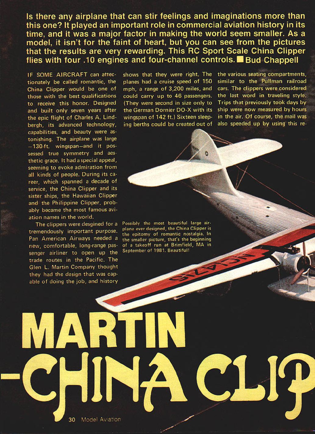
Is there any airplane that can stir feelings and imaginations more than this one? The Martin China Clipper played an important role in commercial aviation history and helped make the world seem smaller. As a model, it isn't for the faint of heart, but the results are very rewarding. This RC Sport Scale China Clipper flies with four .10 engines and four-channel controls.
If some aircraft can affectionately be called romantic, the China Clipper would be among the best candidates. Designed and built only seven years after Charles A. Lindbergh's epic flight, its advanced technology, capabilities, and beauty were astonishing. The airplane was large—130 ft. wingspan—and it possessed true symmetry and aesthetic grace. During its decade of service, the China Clipper and its sister ships, the Hawaiian Clipper and the Philippine Clipper, probably became the most famous aviation names in the world.
Pan American Airways needed a comfortable long-range passenger airliner to open Pacific trade routes. The Glenn L. Martin Company produced a design capable of meeting that need. The Clippers cruised at about 150 mph, had a range of 3,200 miles, and could carry up to 46 passengers. Sixteen sleeping berths could be created from the seating compartments, similar to Pullman railroad cars. Trips that previously took days by ship were now measured in hours, and mail delivery was dramatically accelerated.
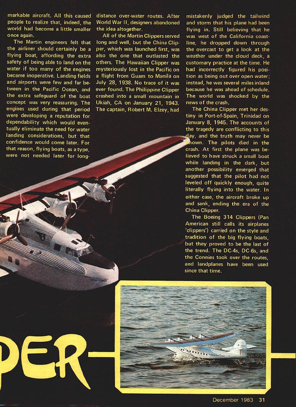
Martin engineers felt the long-range airliner should be a flying boat to allow water landings if engines failed—airfields were scarce across the Pacific. Later engine reliability reduced the need for flying boats, and after World War II designers largely abandoned the concept. All the Martin Clippers served well, but the China Clipper, launched first, outlasted the others. The Hawaiian Clipper was lost in the Pacific on July 28, 1938; no trace was found. The Philippine Clipper crashed near Ukiah, California, on January 21, 1943. The China Clipper itself sank at Port‑of‑Spain, Trinidad, on January 8, 1945, ending the era for that particular airplane.
The Boeing 314 Clippers continued the style and tradition of the big flying boats, but they proved to be the last of the trend. Landplanes—DC‑4s, DC‑6s, and Constellations—took over the routes and have been used ever since.
The China Clipper, NC14716, nicknamed Sweet Sixteen by her pilots, is the subject presented here for modeling pleasure. It is not an easy model to build or fly and is not a casual sport flyer. If you enjoy building classic scale subjects and want a plane that will impress a crowd, this model is an excellent choice.
I believe this is the first RC Sport Scale presentation of the China Clipper. The Smithsonian Institution has a 24‑in. solid display model, but it is a rather poor representation. If you complete this model as drawn and shown, you will own a copy that surpasses Smithsonian quality.
I recommend the builder be experienced with both building and flying multi‑engined RC aircraft. Construction methods are straightforward and conventional, but accuracy and careful attention to detail are essential. Follow plans and specifications without improvisation to achieve the correct total weight and balance. The model's flying characteristics demand an experienced pilot—multi‑engine "heavies" fly differently from single‑engine models and are challenging.
This model has a 74‑in. wingspan, uses four .05–.10 engines, and has an 8 lb. total weight—light for a scale model. The wing loading is low, which enhances flying ability. If you are still determined to try it, let's get started.
Wing construction and modification
I began with the wing and its four engines. After studying photos and reference books, I realized the wing shape and airfoil are close to the Carl Goldberg Skylane 62. I obtained one of the Skylane wing kits and found much of the work partially done.
Build the wing as the kit instructions show up to the point where the leading edge covering is applied. Then:
- With a fine-toothed saw (Zona saw recommended), cut the assembled wing exactly in half. This allows the center constant‑chord section to be flat (no dihedral).
- Pin the two sections to a flat board. Install plywood joiners by cutting away sections of the ribs. Epoxy the joiners to the spars and leading and trailing edges. Apply epoxy liberally to the center joint for strength.
- At the taper starting rib (#7), saw nearly through the structure on the outboard side, leaving about 1/16 in. uncut across the bottom of the wing. Trim gradually to raise the tapered outer sections to the proper dihedral. Add more joiners at rib #7.
- Move the ailerons out from their original positions and extend ribs and spar parts to lengthen the outer panels. Shape tips from block stock and lengthen the trailing edge to meet the ailerons.
- Cover the ailerons with white Super MonoKote and hinge them to the wing with MonoKote strips for a strong, smooth, airtight seal.
Aileron hinges and control layout
I prefer to hide control horns for scale effect. Use larger Robart hinge points and separate one hinge point into two pieces; only the half with the drilled hole is used. The hole accepts the wire from Goldberg control‑horn nylon snap links. Bend the wire at 90°, make a hole in the aileron, and glue the Robart hinge half into the hole. Hook the other end of the wire into a 60° bellcrank located in the wing.
This bellcrank setup yields approximately 20° up-aileron and only 2°–5° down. Reducing down movement lowers drag from the downward aileron and improves turning characteristics.
Engine mounts, fuel, and throttles
- Cut plywood engine plates and epoxy them to the underside of the center wing section.
- Glue plywood engine bearers (drilled to match engine mount holes) to the plates.
- Paint engine mount areas black to seal the wood against oil.
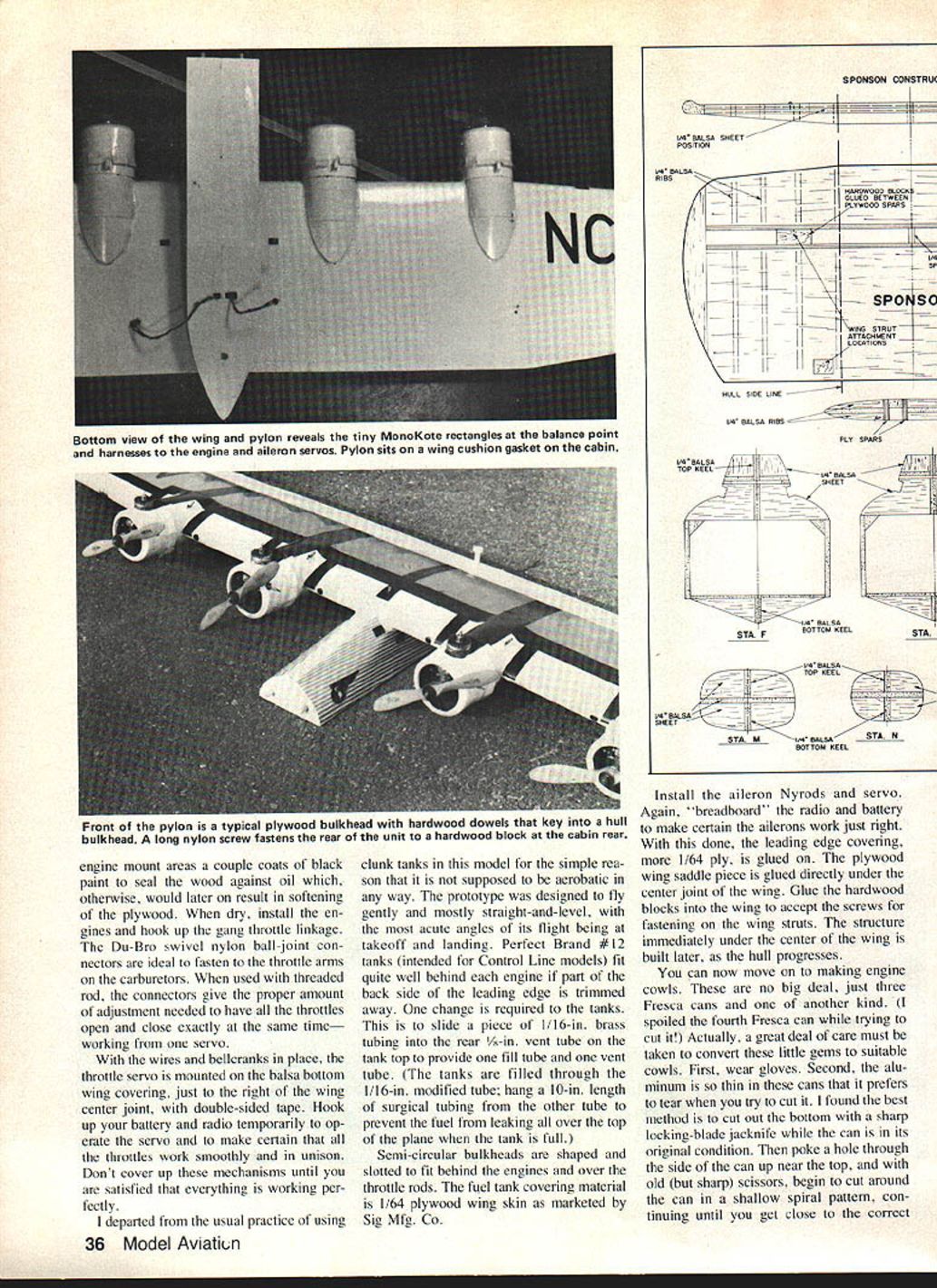
- Install engines and hook up the gang throttle linkage. Du‑Bro swivel nylon ball‑joint connectors and threaded rod work well to synchronize throttles from one servo.
- Mount the throttle servo on the balsa bottom wing covering just right of the wing center joint with double‑sided tape. Temporarily hook up battery and radio to operate the servo and confirm smooth, synchronous throttle operation before covering.
I departed from clunk tanks, since the model is not intended for aerobatics. Perfect Brand #12 Control Line tanks fit well behind each engine if part of the back side of the leading edge is trimmed away. Modify the tank vents by inserting 1/16‑in. brass tubing inside the rear 1/8‑in. vent tube to create a fill tube and a vent tube. Fill through the modified 1/16‑in. tube and hang a 10‑in. length of surgical tubing from the other tube to prevent fuel spillage.
Semi‑circular bulkheads are shaped and slotted to fit behind the engines and over the throttle rods. The fuel tank covering is 1/64‑in. plywood wing skin (Sig).
Install aileron pushrods (Nyrods) and servo. Breadboard the radio and battery again to make sure ailerons are correct before covering the leading edge with more 1/64 ply. Glue the plywood wing saddle under the center joint and glue hardwood blocks to accept wing‑strut screws. Finish the structure under the wing center later as the hull progresses.
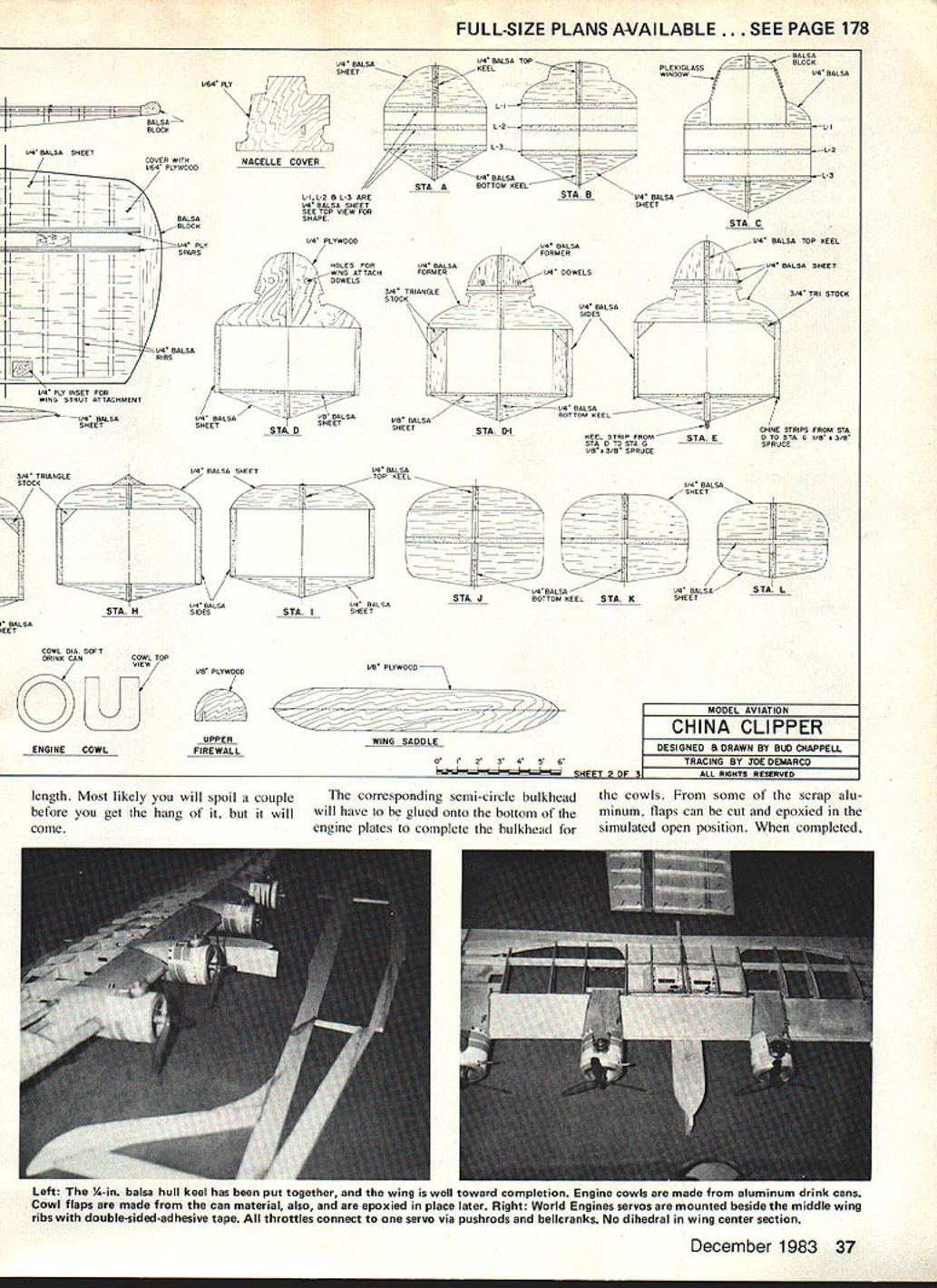
Engine cowls and props
Engine cowls can be made from soft drink cans—three Fresca cans and one of another brand. Take care: the aluminum is thin and tears easily. Cut the bottom out with a sharp locking-blade jackknife while the can is intact, poke a hole near the top, and cut around in a shallow spiral with scissors until you reach the desired length. Expect to spoil a few cans before mastering the technique.
Glue semi‑circular bulkheads to the bottom of the engine plates to complete the cowl bulkheads. From scrap aluminum, cut and epoxy flaps in a simulated open position. Paint cowls with white Sig Plasti‑Namel. Fasten cowls to engine bearers with #0 × 1/8 wood screws after cutting openings to fit around cylinders and needle valve extensions.
I used 6‑4 three‑bladed plastic props on the OS .10 engines and boiled them in silver Rit dye to color and relieve manufacturing stresses. Later, changing to two‑bladed props (Top Flite 7×6) improved water performance.
Adhesives and safety
Use waterproof glues: Ambroid and 5‑minute epoxy are recommended. Take care to keep these products away from children.
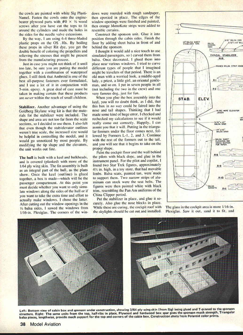
Stabilizer
The Goldberg Skylane wing kit includes materials for the stabilizer. The shape and area are close enough to scale that I used them, modifying the tip shape and elevators. The slightly larger stabilizer improves control and is barely noticeable on the finished model.
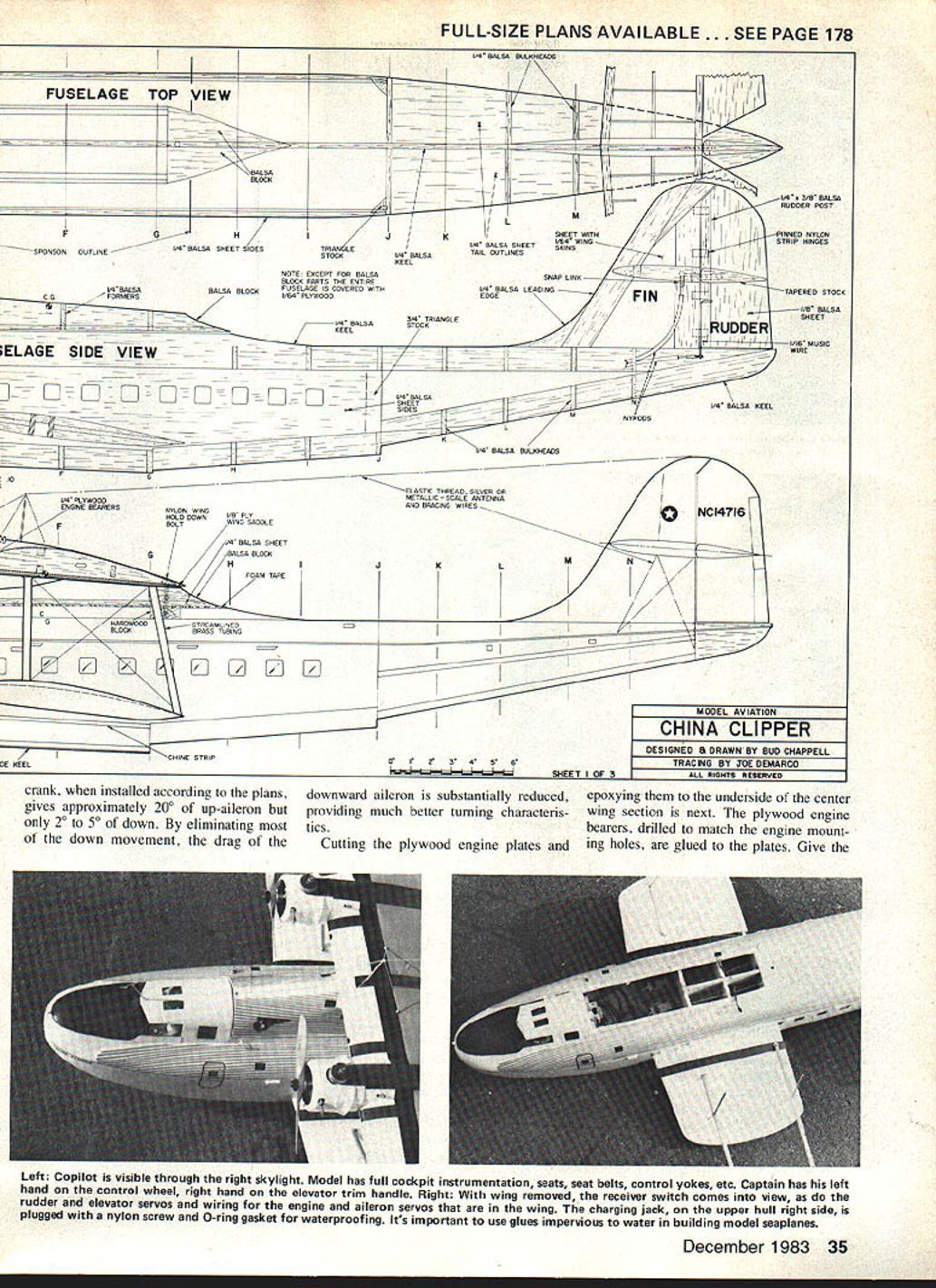
Hull construction
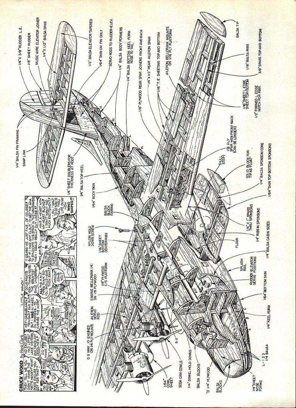
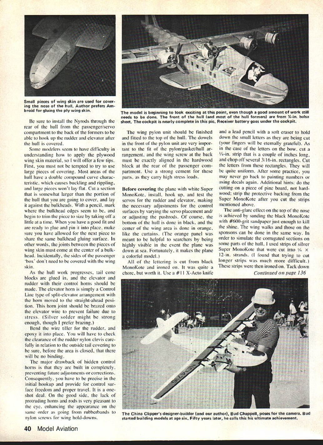
The hull is built with a keel and bulkheads and planked with 1/64‑in. plywood wing skin.
- Build the fin assembly as an integral part of the hull.
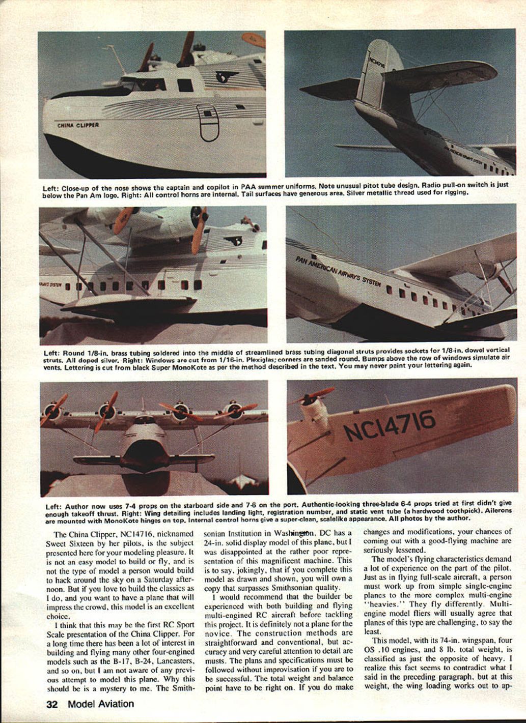
- Glue the keel outline and construct the passenger compartment box. Decide whether to simulate windows or make actual Plexiglas windows. I cut window openings in 1/4‑in. balsa sides and sawed windows from 1/16‑in. Plexiglas, rounded corners with sandpaper, and epoxied them in place. Finish and paint window edges; add orange MonoKote strips to resemble curtains.
- Construct the sponson unit and glue it in through the cabin sides. Finish the floor with sheet balsa in front of and behind the sponson.
For a period touch, I carved simulated passengers from balsa—seven passengers plus two crew and a famous dog—glued near windows.
When gluing the passenger box into the keel, add triangular formers under the floor, then formers L‑1, L‑2, L‑3, and continue aft to the tail until the hull fairing takes shape. Paint the cockpit floor and the wall behind the pilots with black dope and glue in the instrument panel.
I used two Star Trek figures (~4‑1/4 in.) as pilot and copilot, made balsa seats painted tan, and used narrow aluminum strips for seat belts. Paint the pilot figures white with black trim to resemble Pan Am uniforms.
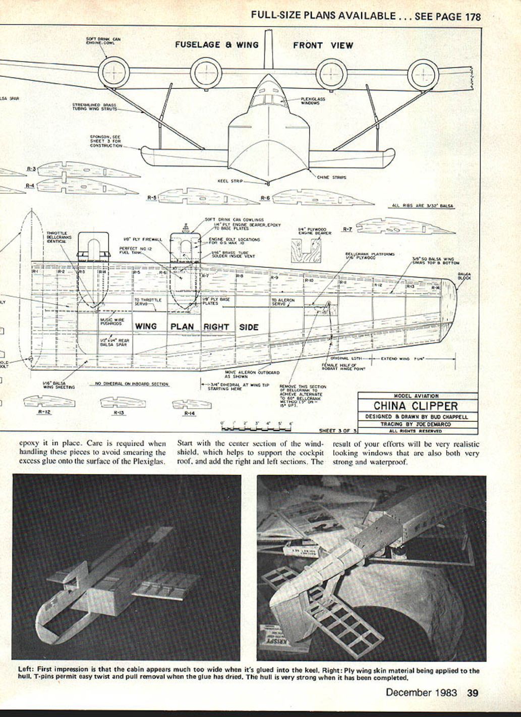
Install the stabilizer and nose blocks, then cut and install the cockpit roof with skylights. Use 1/16‑in. Plexiglas for cockpit glazing; saw to fit, sand, and epoxy in place. Start with the center windshield section, then fit right and left sections. These result in realistic, strong, waterproof cockpit windows.
Be sure to run Nylords from the passenger/servo compartment to the rear formers to hook up rudder and elevator after hull covering.
Applying plywood wing skin to the hull
Tips:
- Avoid using large pieces—many hull areas have double compound curves that cause buckling.
- Cut a piece slightly larger than the area to cover and mark bulkhead edges with a pencil. Trim gradually until the fit is good.
- Ensure joints between skin pieces come at the center of bulkheads so overlapping pieces share a common gluing surface.
- The sides of the passenger box do not require wing skin covering.
As tail cone blocks are glued in, make elevator and rudder with their control horns. The elevator horn is a Control Line split‑elevator type, moved to the straight‑ahead position; brazing the horn onto the elevator wire is recommended to prevent stress failure.
Bend the wire tiller for the rudder and epoxy it in place. Check rudder nylon clevis clearance relative to the outside tail covering to avoid binding.
Hidden control horns are built in and prevent later adjustment, so be precise in initial hookup and ensure control surface freedom and proper travel.
Wing pylon, servos, and covering
Finish and fit the wing pylon to the top of the hull. The dowels in the front of the pylon unit are important for the pylon/gasket/hull fit, and the rear wing screw must align exactly in the hardwood block at the rear of the passenger compartment. Use a strong cement for these high‑stress parts.
Before covering with white Super MonoKote, install, hook up, and test rudder and elevator servos and adjust linkages. The bottom of the hull is covered in black, and the center of the wing area in orange (the orange panel was meant to aid searchers if the plane was down at sea and also makes a colorful model).
All lettering is cut from black MonoKote and ironed on. Use a #11 X‑Acto knife and a soft‑eraser pencil to help hold small letters while cutting. For bow letters, cut 1/4‑in. strips and chop off rectangles to cut uniform letters.
The anti‑glare effect on the top of the nose is achieved by sanding black MonoKote with #600‑grit sandpaper to kill the shine. Wing walks and sponson walks can be done similarly. To simulate corrugated panels, cut silver Super MonoKote into 1/8 × 12‑in. strands and iron them on, stretching slightly as the iron heats.
Wing struts and rigging
The wing struts are functional and strengthen the wing/hull joint.
- Start with four pieces of streamlined brass tubing. Squeeze the ends in a vise to flatten for drilling.
- Determine the vertical smaller strut locations and mark intersection points with masking tape. Drill 1/16‑in. starter holes and then 5/32‑in. through the tape and struts.
- Cut and bend 1/8‑in. brass round tubing per the plan and solder intersections for smooth joints.
- Fit hardwood dowel sections between sponson and wing underside; the brass tubing sockets allow up/down adjustment for fit.
- Paint struts with two coats of silver dope.
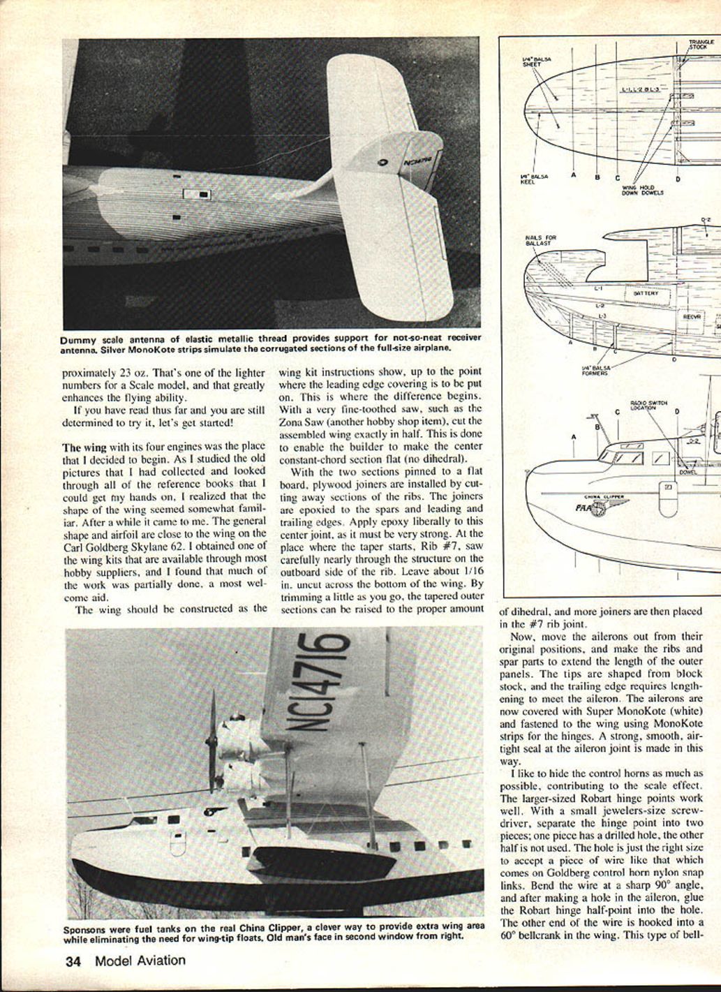
For visible rigging wires, make small hooks from common pins (heads removed) and press into locations shown. Use elastic silver metallic thread to loop from hook to hook; you can rig a whole section with a single piece. Air vents over some passenger windows are small MonoKote‑covered balsa blocks epoxied in place.
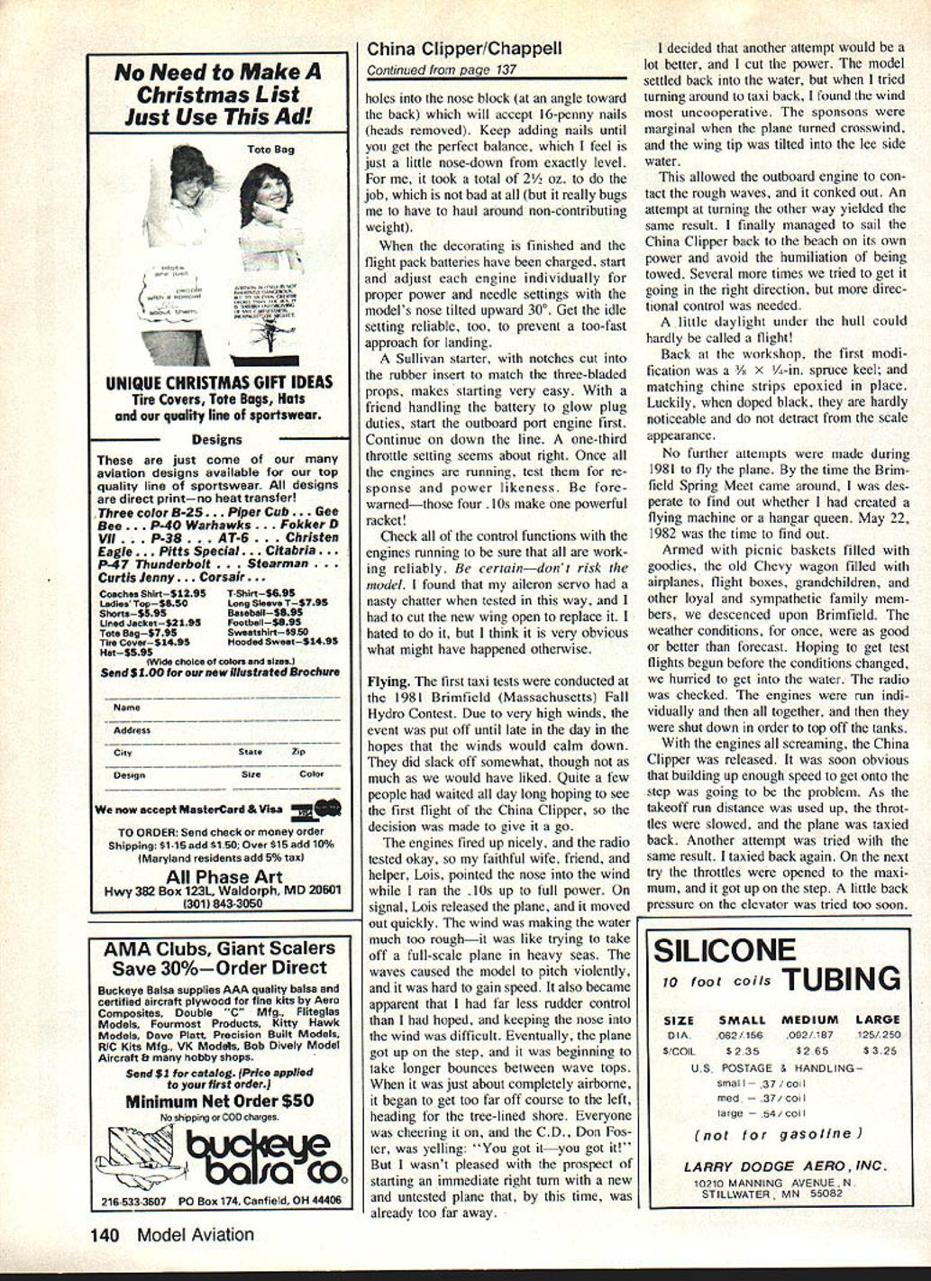
The pitot tube on the cockpit top is built from 1/8‑in. tubing and dowel with a Z‑bent wire glued to the top. The Pan Am logo was positioned differently in photos: in 1935 it appeared on the nose near the plane's name; in 1936 photos it's on the pylon behind the engineer's window. Duplicate small windows and logos in black MonoKote.
Balance and fuel setup
Pre‑flight balance can be tricky. My model turned out tail‑heavy and required nose weight. To locate the desired balance point:
- Put small MonoKote strips under the wing alongside the pylon at the desired CG so you can feel where to lift the model with two fingers.
- Cut the top of the nose block off at the glare‑panel line and remove this front section for reuse.
- Drill angled 1/4‑in. holes into the nose block to accept 16‑penny nails (heads removed). Keep adding nails until the perfect balance is achieved—slightly nose‑down from level. I used 2½ oz. of weight.
Before flying, charge flight pack batteries, start and adjust each engine individually with the model's nose tilted up about 30°, and set reliable idle. A Sullivan starter with notches cut into the rubber insert to match three‑bladed props makes starting easy. Start outboard port engine first and proceed down the line. A one‑third throttle setting is about right for startup. With all engines running, test control functions—especially with engines running because servo chatter or failures become apparent then.
Test flying and modifications
First taxi tests were at the 1981 Brimfield Fall Hydro Contest. High winds made takeoff difficult: rough water caused violent pitching, reduced directional control, and engines contacted waves and quit. After several attempts and being unable to maintain course, the model returned to shore under its own power. The result was marginal taxiing but no successful flight that day.
Back at the workshop, I added a 3/8 × 3/4‑in. spruce keel and matching chine strips epoxied in place. Doped black, they were hardly noticeable and improved steering. No further attempts were made in 1981.
At the Brimfield Spring Meet on May 22, 1982, with good weather, initial attempts again had difficulty building sufficient speed to get on the step. Eventually the plane lifted but was unstable: the port wing rose and the right tip dug into the water, causing a cart‑wheel and killing three engines. During tight circles on the water with one engine idling, another modeler landed and crashed into the starboard wing. The chase boat retrieved the plane.
Repair and rework revealed:
- Keel and chine strips cured steering problems.
- Several inches of wing tip needed rebuilding.
- The hull and sponsons produced suction difficult to overcome during takeoff.
Damaged wing tip sections were rebuilt from scrap. With no MonoKote available, Scotch Brand Magic Transparent Mending Tape made a waterproof, fuel‑resistant skin for repairs. After rebuilding, I suspected the three‑bladed props could be limiting engine RPM on the water. I installed four Top Flite two‑bladed wood 7×6 props, re‑run the engines, reset carburetors, and went back to the water.
On the next attempt, with full power, the model lifted in about 50 ft. I was momentarily slow on controls, but a calm voice at my left elbow coached me—"Bring up that left wing... a little more nose down... keep the right turn no more than 30° bank..." That voice belonged to Len Bell, a Pan Am pilot (14,000 hours) who had actually flown the real China Clipper. With his guidance, I trimmed and flew the model. The plane flew beautifully—docile, smooth, majestic—and the landing was super smooth. Subsequent flights went even better.
Len Bell and I discussed differences in handling between model and full‑scale aircraft. One issue was asymmetric turning: left turns tended to tighten and require opposite aileron as the turn built, while right turns did not tighten. The collective torque of four engines all rotating the same direction likely contributed. After the first flight, about 5° right rudder trim was required to maintain straight flight. Len suggested reducing prop pitch on the outboard starboard engine (#4) and possibly #3 to adjust differential thrust and trim. Down‑elevator was also needed for hands‑off trim.
In summary, after modifications and careful setup, the model China Clipper proved easier to fly than my PBY‑5. At about 8½ lb. fueled weight, it is 3 lb. heavier than the Catalina but has performed very well. The China Clipper was a lot of work, a formidable challenge, and ultimately a great satisfaction—exactly as modeling should be.
Happy flying to you all.
China Clipper Material List
- Carl Goldberg Skylane 62 wing kit
- Aluminum soft drink cans (cowls)
- OS .10 engines
- 2 — 7 × 6 props (starboard side)
- 2 — 7 × 6 props (port side)
- 90° bellcranks (throttles)
- 1/16‑in. balsa sheet, 3 × 36 in.
- 1/8‑in. balsa sheet, 3 × 36 in.
- 1/4‑in. balsa sheet, 3 × 36 in.
- 1/32‑in. balsa sheet, 16 × 6 in. (approx.)
- 12" Perfect brand Control Line fuel tanks
- 1/16‑in. brass tubing, 12 in.
- 1/16‑in. brass tubing, 12 in. (additional)
- 1/8‑in. streamline brass tubing
- 1/8‑in. hardwood dowel, 12 in.
- Duro ball socket fittings
- Sets of 4‑40 engine mounting bolts with nuts
- 16‑in. length medium silicone fuel tubing
- 1/4‑in. hardwood dowel, 12 in.
- 1/4‑in. plywood sheet, 12 × 24 in.
- 3/16‑in. plywood sheet, 6 × 12 in.
- Plywood wing skin, 1/64 × 12 × 48 in. (Sig Mfg. Co.)
- Spruce pieces, 1/2 × 1/4 × 36 in.
- Balsa block, 6 × 4 × 3 in. (nose block)
- 2 — Balsa blocks, 1 × 1½ × 10 in. (sponson tips)
- 1 — Balsa block, 4 × 3 × 4 in. (cockpit roof)
- Package wing cushion tape
- Package servo mounting tape
- 2 — 9/16 × 1/16 × 7 in. hardwood (sponson main spar pieces)
- 2 — 60° bellcranks (ailerons)
- 2 — Robart hinge points, medium size
- 1 — Steel elevator horn, control‑line type, modified
- 1 — Nylon wing screw, 2 in.
- Music wire, 1/16 × 36 in.
- 2 — rolls Super MonoKote, white
- 1 — roll Super MonoKote, silver
- 1 — roll Super MonoKote, orange
- 1 — roll Super MonoKote, black
- 1 — spool elastic thread, silver, metallic
- Misc. — adhesives, crew figures, cockpit detail materials, etc.
Transcribed from original scans by AI. Minor OCR errors may remain.

