

Master Puddle
Joe Beshar
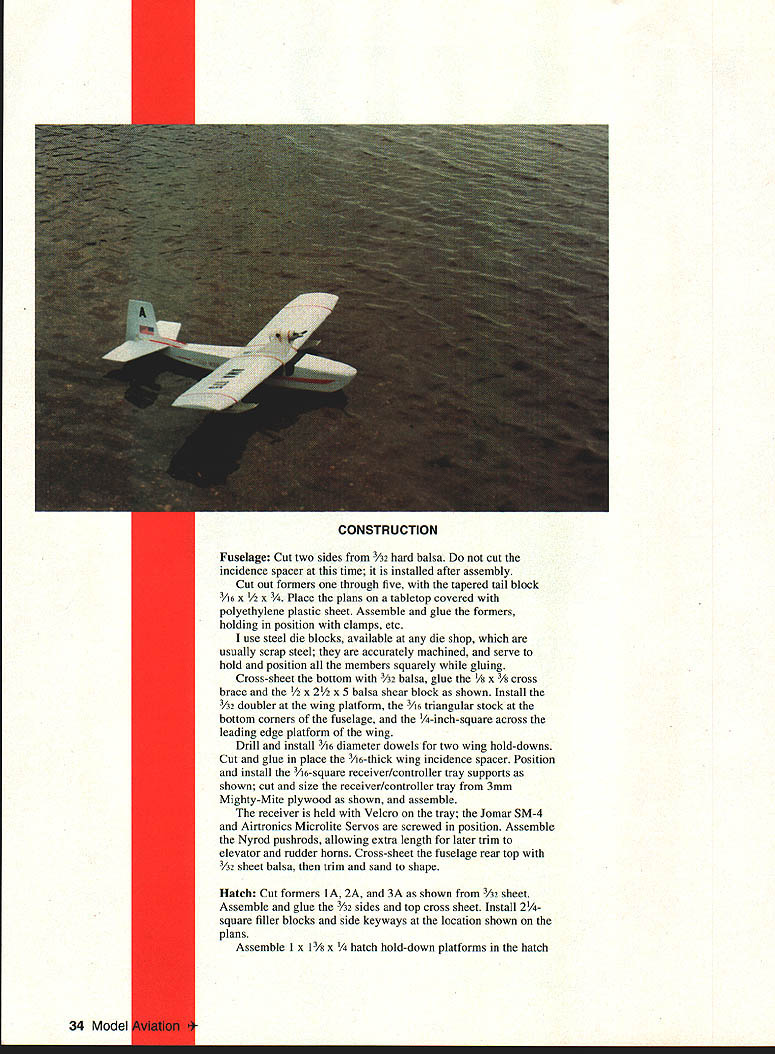
We don't lack flying fields: three-fourths of the earth's surface is an RC flying field. With electric power you can fly anywhere there is water, since it is quiet. You could conceivably fly from any local golf course pond.
Since I had never flown seaplanes, I acquired an ARF Lanier Sea Bird—the quickest way to get involved. I flew it with a Fox .40 glow engine and was immediately hooked on seaplanes.
Shortly thereafter, at the KRC Electric Fly, I learned of the Ace R/C electric-powered Puddle Master—a well-designed, very complete kit. Further interest in electric models resulted in the inspiration for the Master Puddle: a Besharized creation.
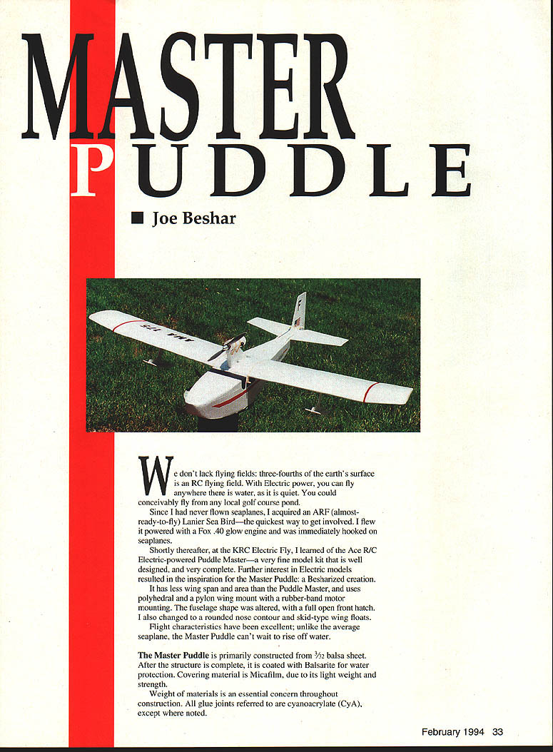
The Master Puddle has less wingspan and wing area than the original Puddle Master, uses polyhedral with a pylon wing mount and rubber-band motor mounting. The fuselage shape was altered to include a full open front hatch, a rounded nose contour and skid-type wing floats.
Flight characteristics have been excellent; unlike the average seaplane, the Master Puddle can't wait to rise off the water.
The model is built primarily from 3/32" balsa sheet. After the structure is complete it is coated with Balsarite for water protection and covered with Micafilm for lightness and strength. Weight of materials is an essential concern throughout construction. All glue joints referred to are cyanoacrylate (CyA), except where noted.
Construction
Fuselage
- Cut two fuselage sides from 3/32" hard balsa. Do not cut the incidence spacer at this time; it is installed after assembly.
- Cut formers 1 through 5 and the tapered tail block from stock per the plans. Cover your tabletop with polyethylene plastic sheet and pin or clamp the parts over the plan.
- Assemble and glue the formers, holding them square with clamps and steel die blocks (accurately machined scrap steel blocks work well).
- Cross-sheet the bottom with 1/16" balsa. Glue the 1/8" x 3/8" cross brace and the 1/2" x 2-1/2" shear block as shown on the plans.
- Install a 3/32" doubler at the wing platform, 3/16" triangular stock at the bottom corners of the fuselage, and 1/4" square across the leading edge platform of the wing.
- Drill and install 3/16" diameter dowels for the two wing hold-downs. Cut and glue in the 3/32" thick wing incidence spacer (to be installed after major assembly if not already done).
- Position and install 3/16" square receiver/controller tray supports. Cut the receiver/controller tray from 3mm Mighty-Mite plywood; assemble and mount so the receiver is held with Velcro. Jomar SM-4 or Airtronics Microlite servos are used and screwed in position.
- Assemble nyrod pushrods, allowing extra length for final trim to elevator and rudder horns. Install elevator and rudder horns.
- Cross-sheet the fuselage rear top with 1/16" sheet balsa; trim and sand to shape.
Hatch
- Cut formers 1A, 2A and 3A from 3/32" sheet. Assemble and glue the 3/32" sides and top cross-sheet.
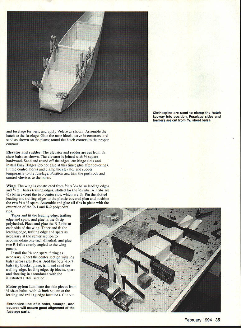
- Install 2" square filler blocks and side keyways at locations shown on the plans. Assemble 1" x 1-3/8" x 1/4" hatch hold-down platforms (or as detailed on the plans). Model clothespins clamp hatch/keyway positions while glue sets.
- Cut any indicated light-thickness areas in the fuselage sides and formers and install Velcro as shown. Assemble the hatch to the fuselage and glue.
- Glue on the nose block, carve contours per the plans and sand. Round hatch corners to the proper contour.
Elevator and Rudder
- Cut elevator and rudder from 1/16" sheet balsa as shown. Join the elevator to a 1/8" square hardwood spar for rigidity.
- Sand and round edges, cut hinge slots and install Easy Hinges. Do not glue hinges permanently until after covering; apply CyA to the hinges after covering.
- Fit control horns and clamp elevator and rudder temporarily to the fuselage. Position and trim pushrods and control clevises to the horns.
Wing
- Construct the wing using slotted leading and trailing edges with 3/32" ribs (except the two center ribs which are 1/8" as shown on the plans).
- Typical stock sizes used: leading edge 5/32" x 7/32", trailing edge 1/8"; spars as shown on the plan (e.g., two 1/4" x 1/2" spars in the last drawing). Pin the slotted leading and trailing edges to the plastic-covered plan and position the spars.
- Assemble and glue ribs in place, leaving R-1 and R-2 (polyhedral ribs) until later.
- Taper-fit the leading and trailing edges and spars where necessary. Prepare tip polyhedral pieces and glue R-2 ribs at each wing side. Fit the center section to accommodate the one-inch dihedral and glue two R-1 ribs evenly angled in the wing panels.
- Install top spars (3/32" or 3/16" as required by your plan fit). Sheet the center section with 1/16" balsa across ribs R-1A.
- Add balsa tip blocks (example size: 1/2" x 7/8" x 7/8" or per the plan), plane, trim and sand the trailing and leading edges, tip blocks, spars and sheeting in accordance with the illustrated airfoil section.
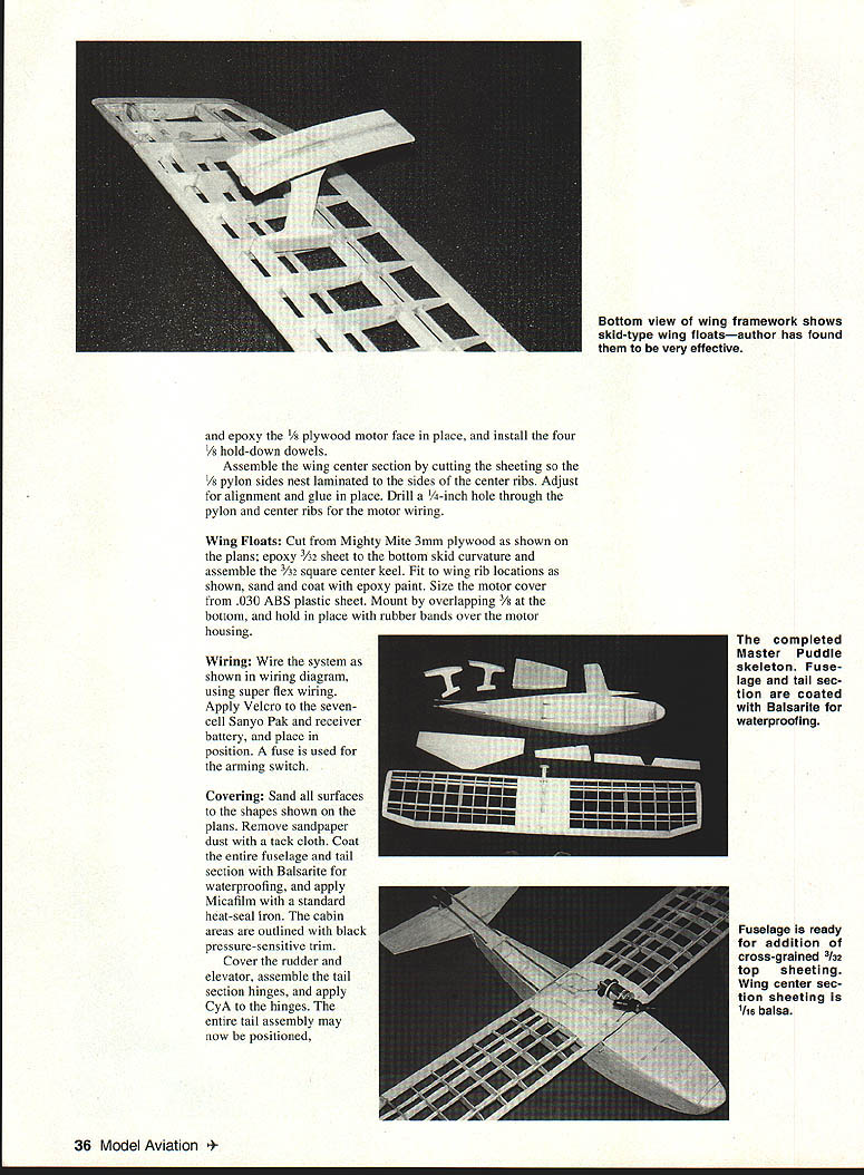
Motor Pylon
- Laminate the pylon side pieces from 1/8" sheet balsa. Install the appropriate leading and trailing edge blocks (e.g., 1/4" square at locations shown) and cut out the pylon.
- Extensive use of blocks, clamps and squares will assure good alignment of fuselage parts.
- Epoxy a 1/8" plywood motor faceplate in place and install the four 1/8" hold-down dowels (or as shown on your plan). Drill a 1/4" hole through the pylon and center ribs for motor wiring.
- Assemble the wing center section so the pylon sides nest against the laminated center ribs; adjust for alignment and glue in place.
Wing Floats
- Cut floats from Mighty-Mite 3mm plywood per the plans. Epoxy 3/32" sheet to the bottom skid curvature and assemble a 3/32" square center keel.
- Fit floats to wing rib locations, sand and coat with epoxy paint for waterproofing.
- Size the motor cover from .030" ABS plastic sheet. Mount by overlapping about 3/8" at the bottom and hold in place with rubber bands over the motor housing.
Wiring
- Wire the system using super-flex wiring per the wiring diagram. Apply Velcro to the seven-cell Sanyo pack and the receiver battery and place them on the tray.
- Use a fuse for the arming switch. Route and secure all wiring through the pylon hole and into the fuselage as shown.
Covering
- Sand all surfaces to the shapes shown on the plans. Remove sanding dust with a tack cloth.
- Coat the entire fuselage and tail section with Balsarite for waterproofing. Apply Micafilm covering with a standard heat-seal iron; Micafilm is recommended for its light weight and strength.
- Outline cabin areas with black pressure-sensitive trim if desired.
- Cover the rudder and elevator, assemble tail hinges and apply CyA to the hinges after covering. Position and glue the tail assembly as required.
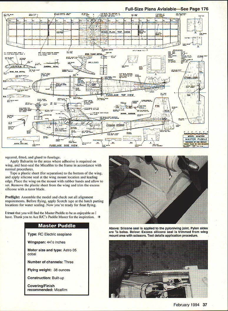
- Apply Balsarite to the areas where adhesive is required on the wing. Tape a plastic separation sheet to the bottom of the wing while sealing and apply silicone sealant at the wing mount location and leading edge. Place the wing on the mount with rubber bands; allow silicone to set, then remove the plastic sheet and trim excess silicone with a razor blade.
Preflight
- Assemble the model and check all alignments, control throws and range checks.
- Before flying, apply Scotch tape at the hatch parting locations for water sealing.
- Now you're ready for float flying.
I trust you will find the Master Puddle to be as enjoyable as I have. Thank you to Ace R/C's Puddle Master for the inspiration.
Specifications
- Type: RC electric seaplane
- Wingspan: 44-1/2 inches
- Motor size and type: Astro .05 Cobalt (or equivalent electric motor as used)
- Number of channels: Three
- Flying weight: 38 ounces
- Construction: Built-up
- Covering/Finish recommended: Micafilm
Transcribed from original scans by AI. Minor OCR errors may remain.

