
MATCHING MOLDS
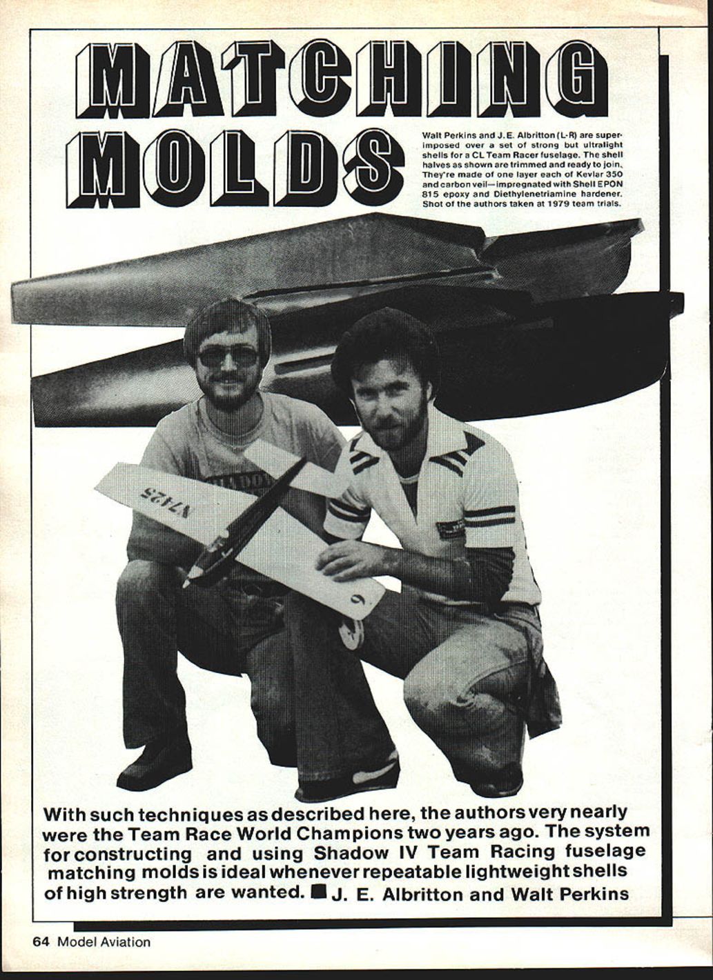
With such techniques as described here, the authors very nearly were the Team Race World Champions two years ago. The system for constructing and using Shadow IV Team Racing fuselage matching molds is ideal whenever repeatable lightweight shells of high strength are wanted. — J. E. Albritton and Walt Perkins
One of the challenging aspects of designing competition model planes is that the rules are usually written to allow some latitude in materials selection and/or construction techniques. Control Line FAI Team Racing rules precisely define minimum fuselage height, width, and cross section while allowing free choice of every other variable. While most designers for this racing class choose the traditional glass-reinforced wood fuselage, J. E. Albritton and I believed we could develop a stronger, lighter fuselage by using very thin moldings of epoxy-impregnated carbon veil paper and Kevlar material.
To summarize five years of development, our first set of molds taught us why other teams were not using molded fuselages: all-glass shells are both heavy and fragile. Our second set of molds showed the strength of Kevlar, as well as the need to split the shells vertically. Kevlar, reinforced with carbon filaments, allowed us to remove all internal formers and most of the traditional hardwood engine mount. The third set of molds opened our eyes to the advantages of making very thin shells with matching male and female molds. We also learned that two-part molds cannot be reinforced with wood if they are expected to last.
Our last set of molds, the subject of this article, incorporates all the tricks we've learned to date. While we would encourage experimentation, it should be helpful to know that we've tried four kinds of epoxy, three styles of Kevlar material, five styles of carbon reinforcement, and two types of glass cloth reinforcement. The sources for everything we presently use are given at the end of this article.
The mold-making techniques described here should be examined by any serious modeler who has a concern for light weight and high strength. While the application in FAI Team Racing takes maximum advantage of these techniques (no minimum weight limit on the model and relatively low absolute strength requirements), we can easily see applications in other kinds of models. A properly designed molded fuselage should have a lower polar moment of inertia than an equally strong wood fuselage. This effect allows a model to turn about its pitch axis faster. All speed-related RC events could use this advantage. Conversely, if a designer needs more strength without weight, this method is the answer.
Plug
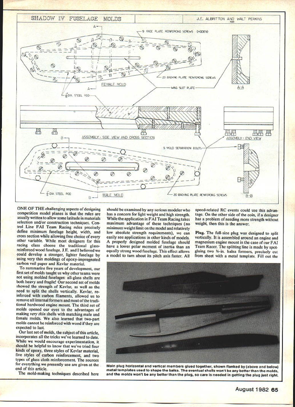
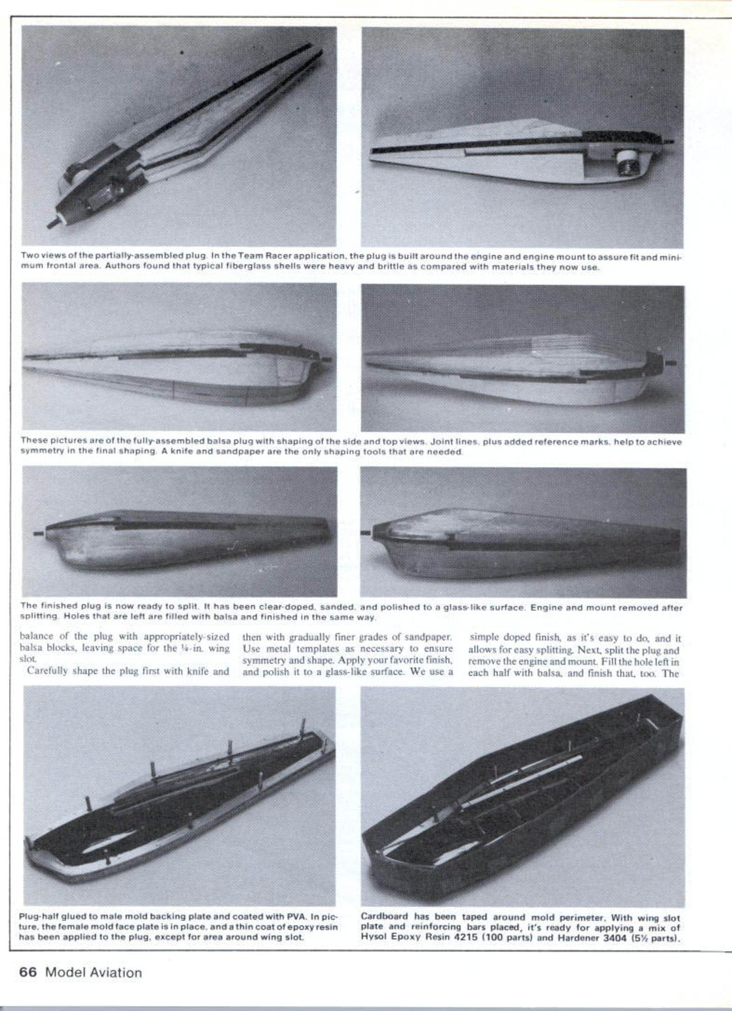
The full-size plug was designed to split vertically. It is assembled around an engine and magnesium engine mount in the case of our FAI Team Racer. The splitting line is made by spot-gluing two 1/8-in. balsa formers, precisely cut from sheet with a metal template. Fill out the balance of the plug with appropriately sized balsa blocks, leaving space for the 1/4-in. wing slot.
Carefully shape the plug first with a knife and then with gradually finer grades of sandpaper. Use metal templates as necessary to ensure symmetry and shape. Apply your favorite finish, and polish it to a glass-like surface. We use a simple doped finish, as it is easy to do and it allows for easy splitting.
Next, split the plug and remove the engine and mount. Fill the holes left in each half with balsa, and finish those areas as well. The upper cowl section is also removed at this time and set aside for use as a windshield form.
Metal mold part preparation
Carefully bandsaw the appropriate pieces of aluminum as shown on the drawing. Drill and countersink all the appropriate screw holes. The two slots required in the aluminum plates for the wing plate and wing access plug should be milled in place for correct alignment and accuracy. Form all 1/8-in.-dia. steel reinforcing bars from common construction steel, which is obtainable from hardware stores. Drill and tap the appropriate mold separation bolt holes around the edge of the female mold face plates.
Prior to using any of the metal parts, thoroughly sand all surfaces to be bonded with epoxy, and degrease the entire part with a grease-cutting solvent. We use acetone. When cleaned, take precautions to avoid contaminating the part with skin oil.
Female mold
Cover the male mold backing plate with Mylar packing tape, and glue the appropriate plug half in place with cyanoacrylate glue. Use modeling clay to fill any gaps between the plate and plug half; a sharp 90° break all the way around is desired. Wipe everything with a tack rag, and coat all surfaces with polyvinyl acetate (PVA) release agent. Set aside to dry.
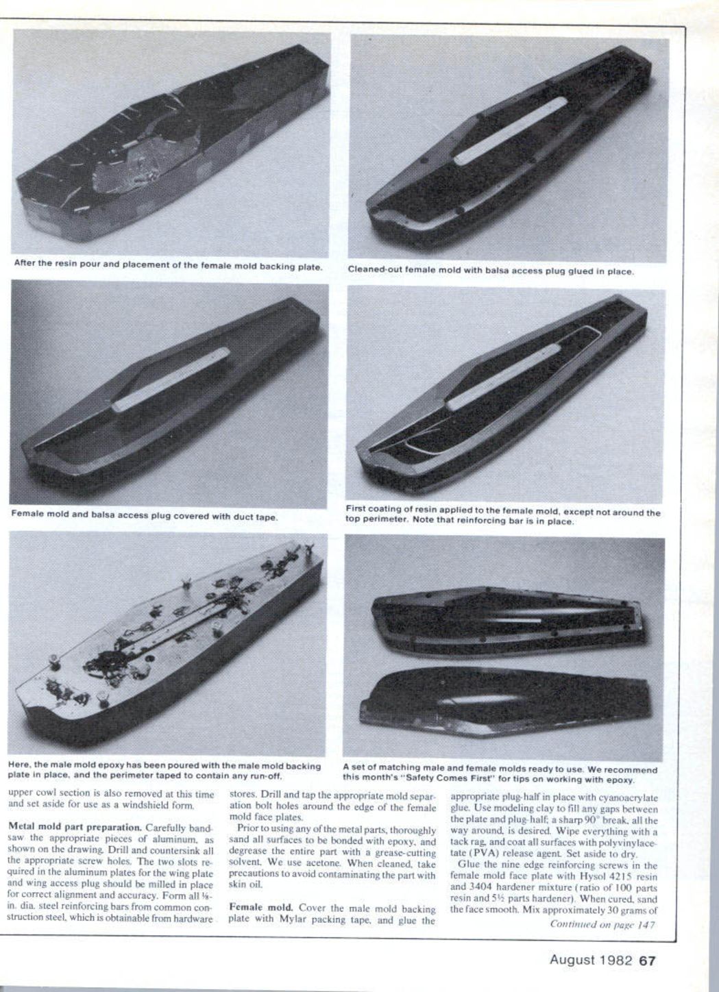
Glue the nine edge reinforcing screws in the female mold face plate with Hysol 4215 resin and 3404 hardener mixture (ratio of 100 parts resin to 5.5 parts hardener). When cured, sand the face smooth. Mix approximately 30 grams of the Hysol mixture and brush a thin "gel" coat over the plug surface—except for the area right around the wing slot. Take care when doing this not to break through the PVA layer. Immediately position the female mold face plate in place and gently clamp until the resin gels. This step places a gel coat of resin on the plug and helps avoid surface bubbles on the mold.
When this resin layer has cured, fabricate a corrugated cardboard box around the edge of the backing plate. Seal all seams with masking tape. Make this box high enough to contain all the remaining resin. Position the wing slot and the reinforcing bars. Also place the remaining perimeter reinforcing bars in place.
Mix approximately 1,400 grams of the Hysol resin and hardener in three batches. Pour separately into the cavity, over the plug, and around the wing plate. Agitate the resin to allow air bubbles to escape. Gently heating the resin with a hair dryer also helps to dispel air bubbles.
Drop the female mold backing plate in place, and force it down until it rests on the face plate reinforcing screws. Some of the resin should ooze up through the reinforcing screw holes and around the wing plate. Push the appropriate reinforcing screws through the backing plate and into the resin.
When the resin has cured, remove the cardboard box and the male mold backing plate. Remove the plug by carefully breaking it up; take care not to gouge the mold surface. Soaking the assembly in water overnight will remove any reluctant pieces of balsa. Clean out any small voids in the mold surface and fill with the Hysol resin mix. Prior to using, sand all surfaces lightly with 600 wet-or-dry sandpaper and polish with polishing compound.
Male mold
Shape the wing access plug from balsa and attach it to the wing plate with cyanoacrylate glue. Cover all surfaces, including the wing access plug, with duct tape. Add a second layer of tape to areas where additional reinforcement is anticipated (in our case, we added a steel pod backing plate). Level all tape seams with modeling clay, and coat all surfaces with PVA.
Mix 30 grams of the Hysol resin and hardener and apply a gel coat to all surfaces except the face plate perimeter. When cured, insert the reinforcing bars. Coat the five separation bolts with silicone grease, and thread them into the male mold backing plate holes until they're flush.
Mix approximately 600 grams of Hysol resin and hardener, and pour it into the female mold. Agitate the mold to release air bubbles. Position the male mold backing plate over the wing access plug and gently press in place. Some resin should ooze out through the reinforcing screw holes and between the two mold halves. Cover the seam between the mold halves with masking tape to contain the resin. Press the appropriate reinforcing screws in place, and set aside to cure.
When cured, remove the masking tape and break out the balsa wing access plug and surrounding duct tape. Apply even, gentle pressure via the separation bolts until the mold halves come apart. Remove the duct tape from the female mold. Clean out all cavity residue and PVA from the male mold half. Fill any small voids with Hysol resin, sand with 600 sandpaper, and polish.
Fuselage shell
Wax all mold surfaces two times, then polish. Coat all mold surfaces with PVA. To get an even coating, it may help to force-dry the PVA with a hair dryer, working in small areas until covered. If there's any doubt as to the completeness of PVA coverage, apply a second coat. Don't take any chances on seizing the mold.
Position the appropriately cut Kevlar or carbon veil paper pieces (one layer of each) in the female mold, and saturate them with a mixture of Shell EPON 815 resin and DTA hardener (mixed in a ratio of 100 parts resin to 11 parts hardener). Use about 30 grams per fuselage half. Tack the reinforcing glass cloth nose piece in place on the male mold half, and join the male and female mold.
Place sufficient C-clamps around the mold to apply even pressure. Stop clamping when firm resistance is felt—excess clamping pressure will destroy the molds and will not result in a thinner shell. Clean off as much resin from the molds as possible. Use facial tissues to remove all excess resin from the wing access hole.
After letting the molds sit at room temperature for two hours, bake in an oven at 175–200°F (79–93°C) for two hours. Remove from the oven and separate the mold halves while they are still warm. It's much easier to take the shell out of the mold while warm.
Mold maintenance
Inspect the molds after every run, and correct any problems before the next use. Always wax before a run, and make sure the molds have a complete PVA coating. Clean the molds every five runs with detergent and water.
Sources
- 2024 aluminum for mold plates: local metal supply company.
- Flat-head machine bolts and 1/4-in. steel wire: hardware store.
- Hysol resin and hardener: TMR Mfrs., 9016 Rosehill Rd., Lenexa, KS 66215; Tel. (913) 888-2606.
- Mold release wax and PVA: local fiberglass fabricating company.
- Kevlar (Style 350): United Plastics Products, P.O. Box 15766, Orlando, FL 32858; Tel. (305) 295-7911.
- Carbon veil (50 gm/m^2): Union Carbide Corp., 270 Park Ave., New York, NY 10017; Tel. (Sales) (312) 454-2000.
- Shell EPON 815 resin and DTA hardener: Miller-Stephenson, Danbury, CT; Tel. (203) 743-4447.
Transcribed from original scans by AI. Minor OCR errors may remain.

