
Matching Propeller to Model Mission
Don Brooks
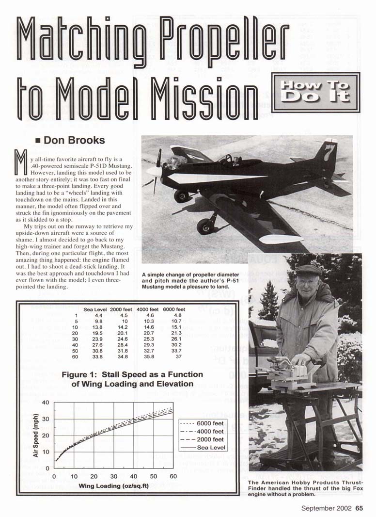
My all-time favorite aircraft to fly is a .40-powered semiscale P-51D Mustang. However, landing this model used to be another story entirely: it was too fast on final to make a three-point landing. Every good landing had to be a "wheels" landing with touchdown on the mains. Landed in this manner, the model often flipped over and struck the fin ignominiously on the pavement as it skidded to a stop. My trips out on the runway to retrieve my upside-down aircraft were a source of shame.
Then, during one particular flight, the most amazing thing happened: the engine flamed out. I had to shoot a dead-stick landing. It was the best approach and touchdown I had ever flown with the model; I even three-pointed the landing.
With the 10 x 6 propeller I was using and with the engine at idle, the model's airspeed was too high for an easy approach and landing. To reduce the airspeed on final, I switched to an 11 x 5 propeller. What a difference! The P-51 was still a pleasure to fly, and landings no longer ended with a flip and skid on the fin. Sometimes, when not limited by the pilot's skill, the landings were even graceful.
Whether you are flying a hot warbird or a slow-flying Piper Cub, the propeller you select makes a great difference in how a model performs. With the right propeller for the model's mission, each flight is a delight.
I judge the model's mission to be adequate performance in each of three phases of flight:
- Takeoff and maneuvering
- Cruise (level flight)
- Landing
The takeoff-and-maneuvering phase tends to require a larger-diameter but shallower-pitch propeller for maximum static thrust. Wing lift increases with the square of airspeed. To maintain level flight for an aircraft with high wing loading, we must fly at a higher cruise airspeed; for cruise we therefore may need a more steeply pitched propeller. If we increase propeller pitch, we may also have to decrease propeller diameter to keep the engine rpm in the best operating range. If we don't have flaps on the aircraft, we may need a lower-pitched propeller for the landing phase.
Since most of us don't have a variable-pitch propeller on our models, selecting a propeller is a compromise to satisfy at least the minimum requirement for each phase of flight.
To make informed judgments about propeller choice, I present three tools you can use:
- Graphs for calculating stall and minimum cruise speeds
- Graphs for calculating pitch speed (relating rpm and pitch to theoretical airspeed)
- Equations and a graph for calculating static thrust produced by a propeller
To use these tools you will need a tachometer and a way to calculate or measure static thrust (I describe simple methods below). I make the judgments based on two rpm measurements: one at full throttle and one at idle.
Equations
The following equations are used in the examples and graphs.
Stall-speed equation (derived from the lift equation in Martin Simons' Model Aircraft Aerodynamics): V_stall = 5.46 * sqrt(W/S) / sqrt(d * C_l)
- V_stall: stall speed in mph
- W: weight of the aircraft in ounces
- S: wing area in square feet
- d: air density in grams per liter
- C_l: lift coefficient (dimensionless)
Thrust equation: f = (C_t * d * n^2 * D^4) / 1000
- f: thrust force in ounces
- C_t: propeller thrust coefficient (dimensionless)
- d: air density in grams per liter
- n: rpm
- D: propeller diameter in meters (inches / 39.37)
Air-density equation: d = 11.79 * P / T
- d: air density in grams per liter
- P: local barometric pressure in inches of mercury
- T: air temperature in degrees Kelvin
- T(K) = [(T°F - 32) * (5/9)] + 273.16
Stall and Cruise Airspeeds for Models
An estimated stall speed can be calculated using the stall-speed equation above. To make the calculation easier, I plotted graphs (Figure 1) of model stall speed as a function of wing loading for four elevations: sea level, 2,000 ft, 4,000 ft, and 6,000 ft.
In the calculations for these graphs I assumed:
- Lift coefficient C_l = 1.3 (approximate near-stall value for several common airfoils)
- Temperature = 70°F
- Appropriate barometric pressure for each elevation
To use the graph:
- Calculate wing loading = ready-to-fly weight (oz) / wing area (sq ft).
- Locate the wing-loading value on the horizontal axis.
- Move upward to the curve for your flying-field elevation (or estimate between curves).
- Read stall speed from the vertical axis.
Example — P-51:
- Ready-to-fly weight: 88 oz
- Wing area: 490 sq in = 3.4 sq ft
- Wing loading: 26 oz/sq ft
- Flying-field elevation: 4,740 ft
- Stall speed (from Figure 1): 24 mph
Bob Benjamin (Model Airplane News, "Electric Power for Scale Models") recommended a minimum level-flight cruise speed of at least twice the stall speed. For the P-51, that gives a minimum cruise speed of 48 mph.
Keep the stall and minimum cruise speeds in mind when you analyze pitch speed and thrust.
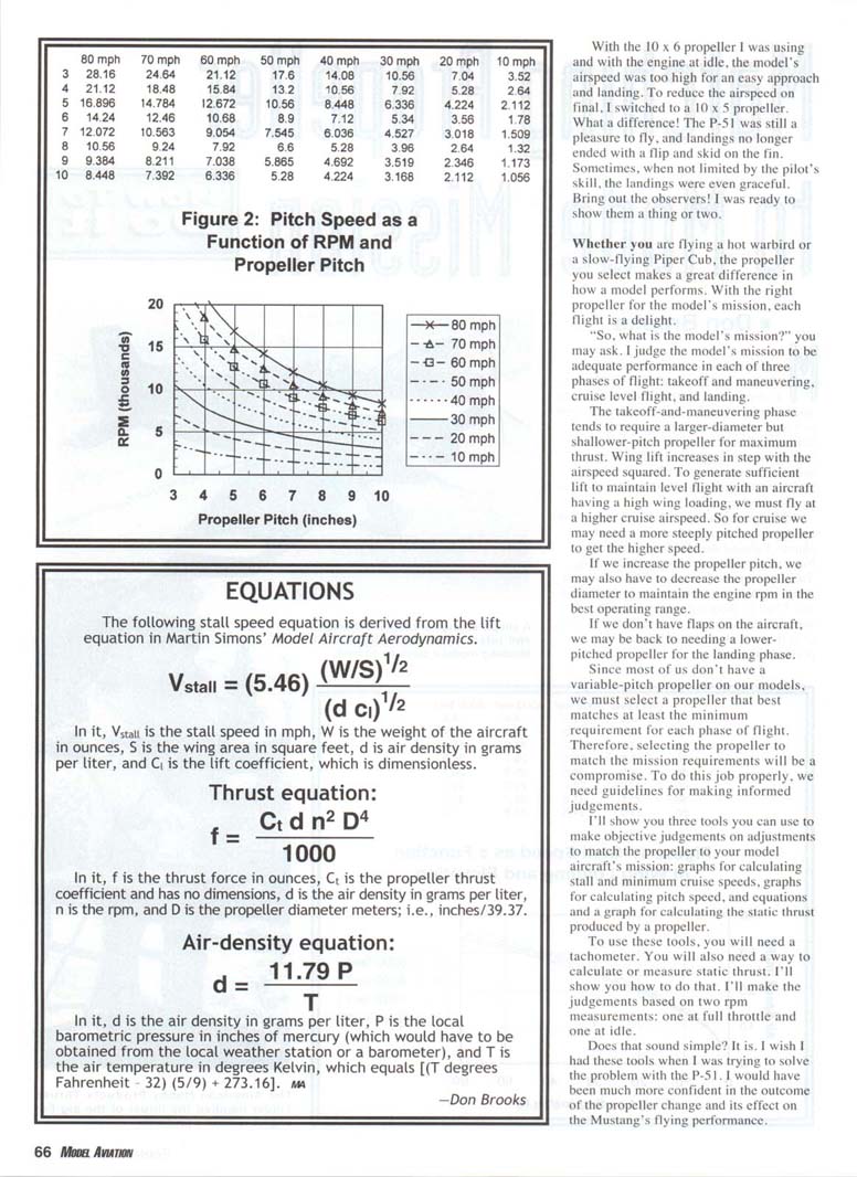
Pitch Speed at High and Low Throttle
Figure 2 shows lines of constant pitch speed for various combinations of propeller pitch and propeller rpm. The pitch speed is the theoretical maximum level-flight airspeed for a particular propeller rpm if the propeller had zero slip and the model had no drag.
In practice, propellers slip and models have drag. However, the propeller also unloads in flight, which typically increases in-flight rpm relative to static ground rpm. This unloading partly compensates for slip and drag. For our purposes I assume the high-throttle pitch speed approximates high-throttle level-flight airspeed — a useful gauging tool though not exact.
Example — P-51 with 10 x 6 propeller:
- Measured rpm: high throttle = 11,000 rpm; idle = 3,000 rpm
- On Figure 2, pitch of 6" at 11,000 rpm corresponds to a pitch speed of ≈ 63 mph (about one-third of the way between 60 and 70 mph lines) — well above the minimum cruise speed (48 mph).
- At idle (3,000 rpm), pitch speed is ≈ 17 mph, which is below the stall speed (24 mph). However, 17 mph is not far below stall speed and explains why the model would not settle easily on final — the propeller was trying to drive the aircraft forward even at idle.
Change to 11 x 5 propeller:
- Reason: reduce low-throttle pitch speed without losing takeoff/manoeuvering thrust.
- Measured rpm with 11 x 5: high = 10,200 rpm; low = 2,500 rpm
- From Figure 2 (pitch = 5"):
- High-throttle pitch speed ≈ 48 mph (right at the minimum cruise speed)
- Low-throttle pitch speed ≈ 12 mph (roughly half the stall speed)
- With the model flying faster than stall speed on final, the propeller (trying to move forward at ≈12 mph) acts like a brake and helps slow the model, producing an easy, steady descent for landing.
This change preserved cruise capability and reduced final-approach speed, improving landings.
Takeoff and Maneuvering Thrust
You may worry that reducing pitch compromises takeoff and maneuvering thrust. To check, calculate or measure static thrust.
Calculation requires:
- Thrust coefficient C_t for the propeller
- Air density d (from local pressure and temperature)
- Measured rpm
Example calculations for the Mustang:
- Thrust coefficients (Master Airscrew data):
- 11 x 5: C_t = 0.079
- 10 x 6: C_t = 0.099
- Local conditions (my flying field at 4,740 ft):
- Average barometric pressure: 25.30 inHg
- Temperature assumed: 70°F
- Calculated air density: d = 1.014 g/L
- Using the thrust equation:
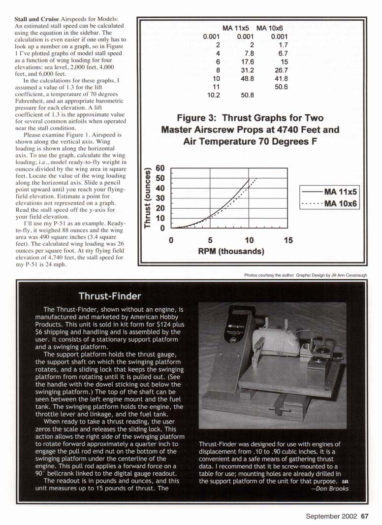
- Calculated thrust of the 11 x 5 at 11,000 rpm (and d = 1.014 g/L): 50.8 oz
- Thrust of the 11 x 5 at 10,200 rpm: 46 oz
Even though the 11" propeller had a lower thrust coefficient and operated at a lower maximum rpm with the K&B .40 engine, it produced equivalent thrust to the 10" prop because thrust scales with the fourth power of propeller diameter.
If you prefer not to calculate, measure static thrust directly:
- Rough method: attach a spring scale to the tail of the aircraft and perform a run-up with the propeller; read static thrust.
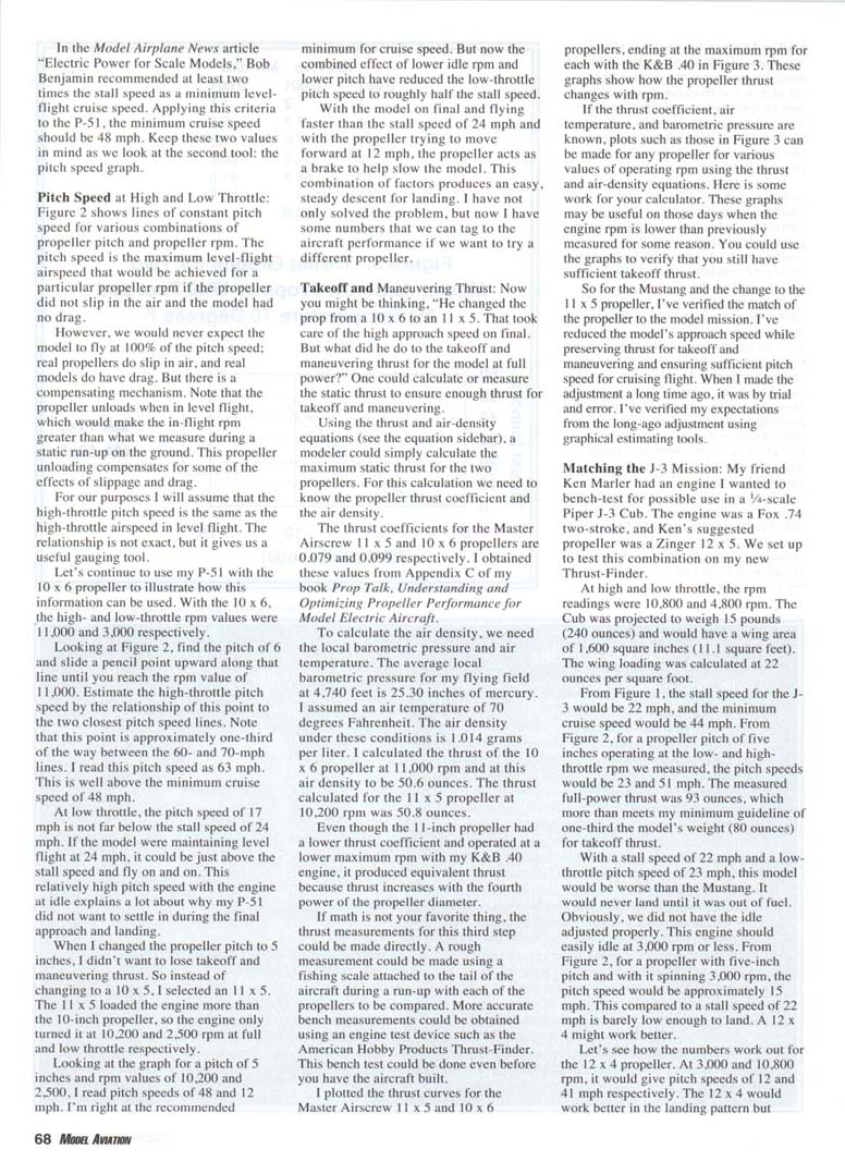
- More accurate: use a bench device such as the American Hobby Products Thrust-Finder.
I plotted thrust curves for the Master Airscrew 11 x 5 and 10 x 6 propellers (Figure 3), showing thrust vs rpm for each propeller up to the maximum rpm measured with the K&B .40. If you know C_t, air temperature, and barometric pressure, you can create similar plots for any propeller and a range of rpms using the thrust and air-density equations. Such plots are useful if engine rpm changes from prior measurements.
With the 11 x 5, I verified:
- Reduced approach speed
- Preserved takeoff and maneuvering thrust
- Adequate cruise pitch speed
Matching the J-3 Mission
My friend Ken Marler brought an engine (Fox .74 two-stroke) for a possible 1/4-scale Piper J-3 Cub. Ken suggested a Zinger 12 x 4 propeller. We bench-tested the combination with a Thrust-Finder.
Measured rpm: high = 10,800 rpm; low = 4,800 rpm.
Projected Cub:
- Weight: 15 lb = 240 oz
- Wing area: 1,600 sq in = 11.1 sq ft
- Wing loading: 22 oz/sq ft
From Figure 1:
- Stall speed ≈ 22 mph
- Minimum cruise ≈ 44 mph
From Figure 2 (pitch = 4"):
- Pitch speeds at measured rpms: low ≈ 23 mph; high ≈ 81 mph
Measured full-power static thrust: 93 oz (meets my minimum guideline of one-third the model's weight: 240 / 3 = 80 oz).
Problem: low-throttle pitch speed (23 mph) is above the stall speed (22 mph). This combination would make landing difficult unless idle rpm is reduced. The Cub's idle can be easily set to 3,000 rpm or less.
- For a propeller with 5" pitch at 3,000 rpm, pitch speed ≈ 15 mph — just low enough relative to a 22-mph stall.
- A 12 x 4 at 3,000 and 10,800 rpm would give pitch speeds of ≈ 12 and 41 mph respectively, which would work better in the landing pattern while still providing adequate takeoff thrust if the engine behaves as measured.
Summary
What we have done:
- Defined the model mission as adequate performance in takeoff/maneuvering, cruise, and landing.
- Examined three objective tools that use rpm readings to help match a propeller to a model mission:
- Stall and minimum-cruise-speed graphs (Figure 1)
- Pitch-speed graph relating rpm and propeller pitch to theoretical airspeed (Figure 2)
- Thrust calculations/plots using propeller thrust coefficients and air density (Figure 3)
Practical notes:
- You need a tachometer and a way to measure or calculate static thrust.
- Simple thrust checks can be done with a spring scale; more accurate bench tests can be done with devices such as the Thrust-Finder.
- Figures 1 and 2 are broadly useful and can be laminated for field use. Figure 3 is specific to propeller C_t, air temperature, and barometric pressure; construct your own Figure 3 for your propellers and location using the thrust and air-density equations.
Have you matched the propeller on your favorite model to its mission? Try it — a successful match makes flying much more fun. Good flying!
MA
Don Brooks 900 Bower Dr. Idaho Falls, ID 83404
References and Source
- Martin Simons, Model Aircraft Aerodynamics (ISBN 1-85486-121-2), Argus Books (1994). See page 21.
- Bob Benjamin, "Electric Power for Scale Models," Model Airplane News, January 2001, page 82.
- Donald W. Brooks, Prop Talk — Understanding and Optimizing Propeller Performance for Model Electric Aircraft (ISBN 0-9657014-0-9), ARPI Books. See pages 77 and 80.
- Thrust-Finder: American Hobby Products, 12 West Hill Cir., Reading, MA 01867.
Transcribed from original scans by AI. Minor OCR errors may remain.

