
Maule M-5 Lunar Rocket
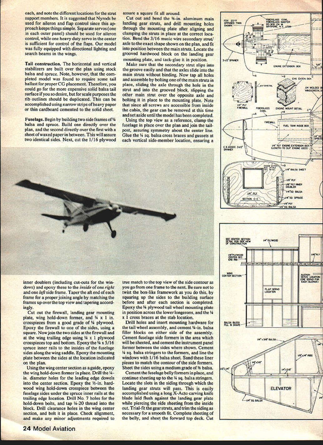
A remarkable airplane turned into a remarkable RC model, the Lunar Rocket is a good example of modern commercial aviation: a workhorse with outstanding STOL capability. It's a real crowd pleaser in Quarter Scale. — Dom Palumbo and Myron Pickard
Nestled unobtrusively in four modern hangars at the Air Force's abandoned Spence air base, just outside Moultrie, GA, Maule Aviation Corp. is one of the latest arrivals on the commercial aviation frontier. The company's president, Belford Maule, and his wife June opened the doors in 1974 to produce and market their original-design airplanes. The M-5 Lunar Rocket is the only airplane produced by the 75 employees of this small but prosperous company, and two complete aircraft come off the assembly line each week.
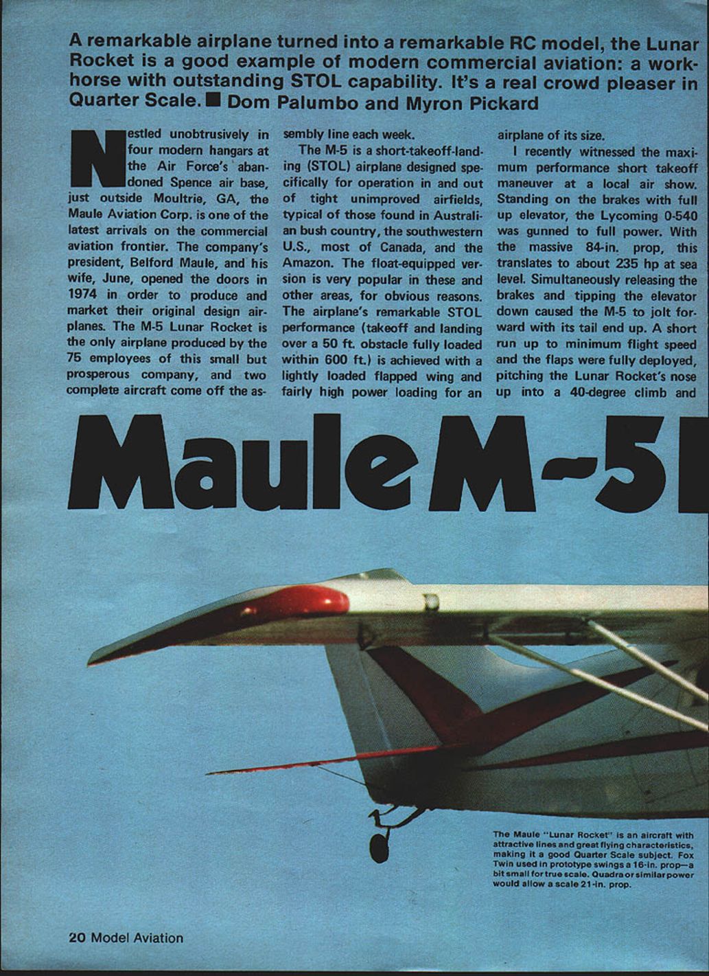
The M-5 is a short-takeoff-and-landing (STOL) airplane designed specifically for operation in and out of tight unimproved airfields typical of Australian bush country, the southwestern U.S., much of Canada, and the Amazon. The float-equipped version is very popular in these and other areas. The airplane's remarkable STOL performance (takeoff and landing over a 50 ft obstacle fully loaded within 600 ft) is achieved with a lightly loaded flapped wing and fairly high power loading for an airplane of its size.
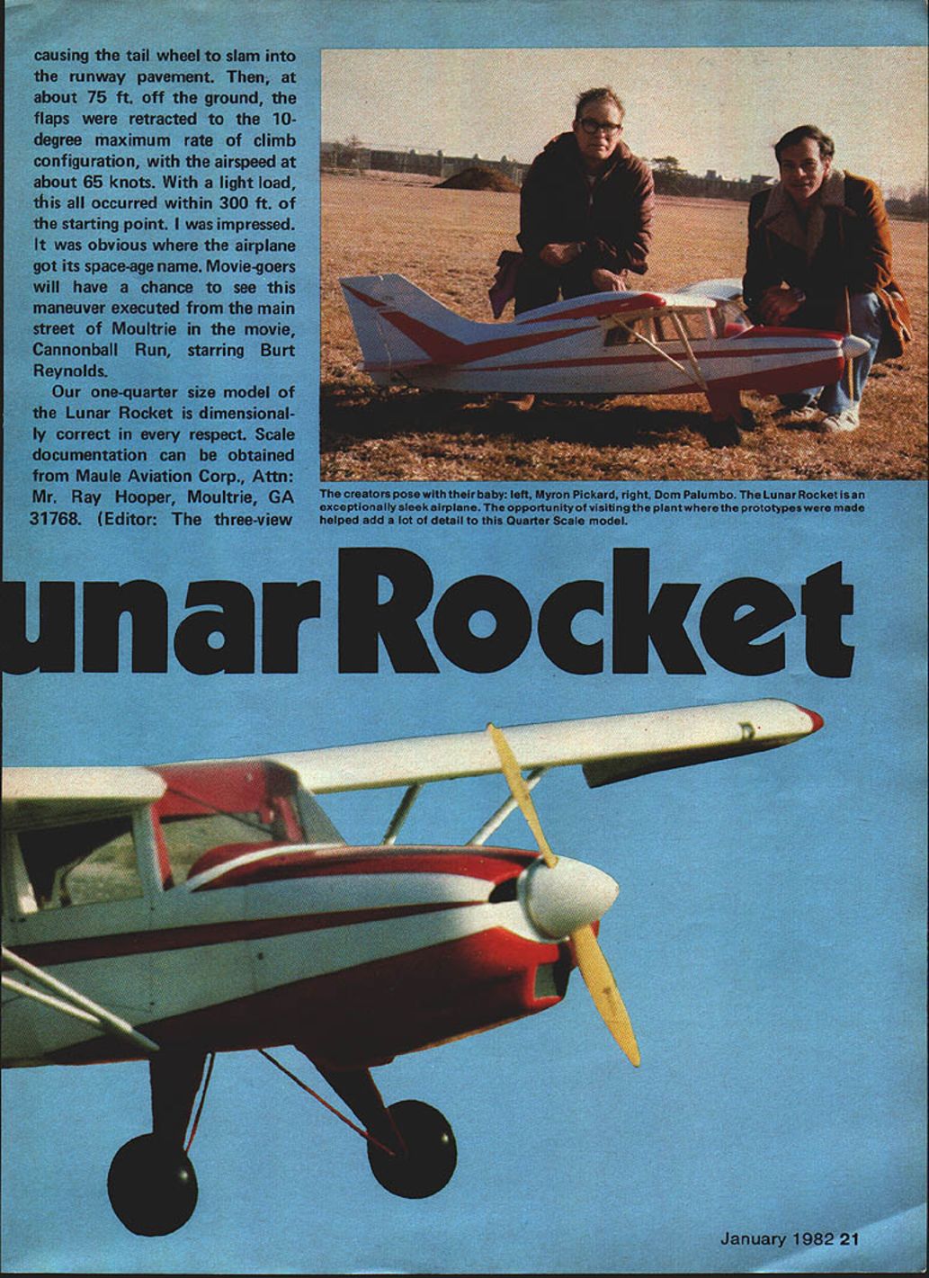
I recently witnessed the maximum-performance short-takeoff maneuver at a local air show. Standing on the brakes with full up elevator, the Lycoming O-540 was gunned to full power. With the massive 84‑in. prop, this translates to about 235 hp at sea level. Simultaneously releasing the brakes and tipping the elevator down caused the M-5 to jolt forward with its tail end up. A short run up to minimum flight speed and the flaps were fully deployed, pitching the Lunar Rocket's nose up into a 40° climb and causing the tailwheel to slam into the runway pavement. Then, at about 75 ft off the ground, the flaps were retracted to the 10° maximum-rate-of-climb configuration, with the airspeed at about 65 kt. With a light load, this all occurred within 300 ft of the starting point. I was impressed.
It was obvious where the airplane got its space-age name. Movie-goers will have a chance to see this maneuver executed from the main street of Moultrie in the movie Cannonball Run, starring Burt Reynolds.
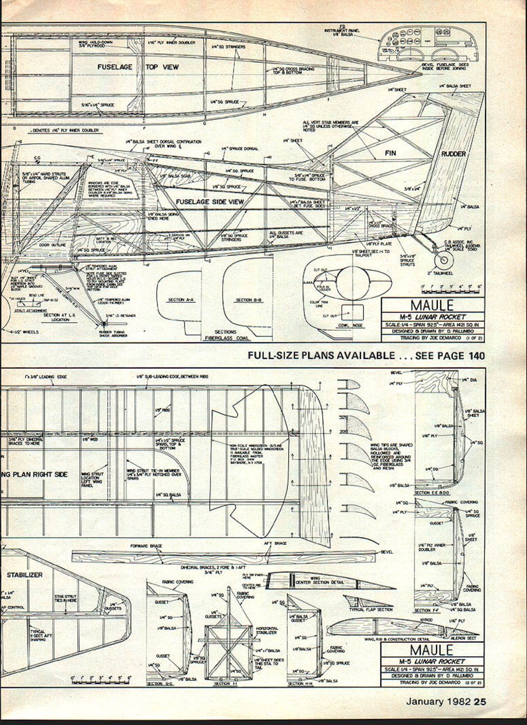
Our one-quarter-size model of the Lunar Rocket is dimensionally correct in every respect. Scale documentation can be obtained from Maule Aviation Corp., Attn: Mr. Ray Hooper, Moultrie, GA 31768. (Editor: The three-view drawing presented with this article was traced from a factory drawing.)
Specifications
- Scale: 1/4
- Span: 92.5"
- Area: 442 sq. in.
- Designed & drawn by: D. Palumbo
- Tracing by: Joe DeMarco
- Full-size plans available: see page 140
Distinctive features
One of the most distinctive features of this airplane is the conformal dorsal fin. The full-size Razor‑back covering is a dope‑shrinkable fiberglass, which is not suitable for models because of its tremendous shrink factor. Extreme care and skill must be exercised when the actual airplane is covered; too much dope in the wrong place will actually cause the steel-tube structure to bend out of shape as the material shrinks. For the model we achieved the conformal dorsal using Super Coverite. A key to success is patience and a very gentle application of heat.
Wing construction
- The wing is in three sections: the center and two outer panels. These can be bonded together permanently or left independent for ease of storage and transportation.
- The flat‑bottom modified USA35B airfoil used on the full-size airplane was checked and found suitable for the model.
- Wing sections are built directly over the plan on a flat building board.
- Note: the outer panel rib layout is such that both left and right panels can be built over the same plan. Make allowance for the passage of the dihedral bracing on the inboard side of the center section.
Controls and electrics
- For aileron and flap controls we used nylon rods for simplicity.
- Use separate servos in the outer panels for aileron control.
- Use a heavy-duty servo in the center section to operate the flaps on a fully equipped model.
- Provision for directional lighting and search beams in the wings is included on the plans.
- Our model was fully equipped with directional lighting and search beams in the wings.
Recommended servos and linkage
- Ailerons: one servo in each outer panel.
- Flaps: heavy-duty servo in the center section.
- Linkage: nylon rods (or Nyrods) keep things simple and reliable.
Tail construction
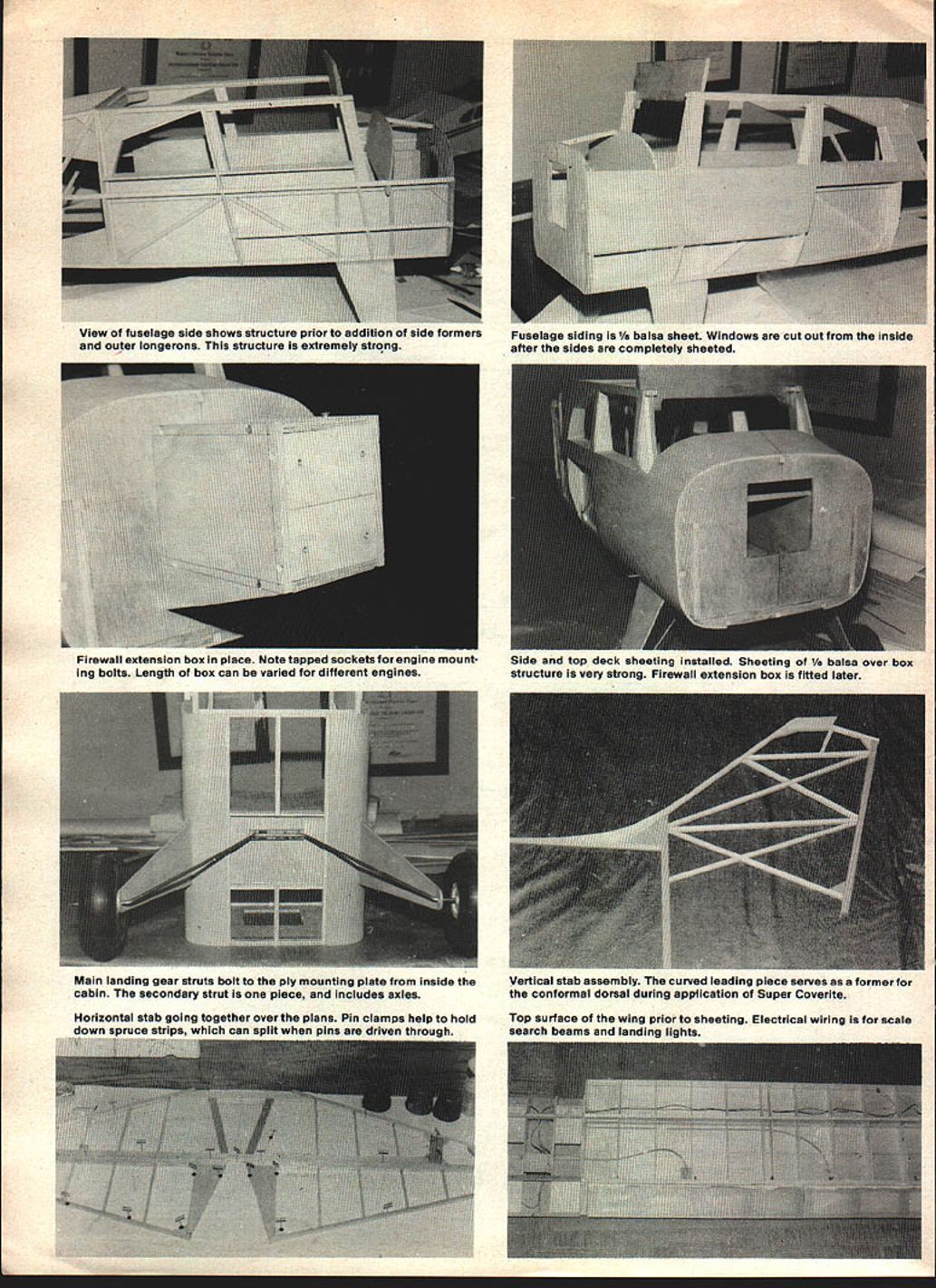
The horizontal and vertical stabilizers are built over the plan using stock balsa and spruce. The completed model was found to require some tail ballast for proper center-of-gravity placement. If you desire scale solid balsa tail surfaces, duplicate the rib outlines by using narrow strips of heavy paper or thin cardboard cemented to a solid sheet.
Fuselage
Begin by building two side frames of 1/4" balsa and spruce. Build one directly over the plan and the second directly over the first with a sheet of waxed paper between them to assure two identical sides.
- Cut the 1/16" plywood inner doublers (including the cutouts for the windows) and epoxy these to the inside of the right and left side frames.
- Taper the aft ends of the frames to the proper joining angle by matching the frames up over the top view and tapering accordingly.
- Cut out the firewall, landing gear mounting plate, wing hold‑down former, and 1/4" x 1" crosspieces from good-grade 1/4" plywood. Epoxy the firewall to one of the sides using a square to ensure accurate alignment.
- Join the two sides at the firewall and at the wing trailing edge using 1/4" x 1" plywood crosspieces top and bottom.
- Epoxy the 1/4" x 5/16" spruce inner rails to the insides of the fuselage sides along the wing saddle. Epoxy the mounting plate between the sides at the location indicated on the plan.
- Using the wing center section as a guide, epoxy the wing hold‑down former in place. Drill the 1/4" diameter holes for the leading-edge dowels into the center section.
- Epoxy the 1/8" hardwood wing hold‑down crosspiece between the fuselage sides under the spruce inner rails at the trailing-edge location. Drill No. 7 holes for the hold‑down bolts and tap 1/4‑20 thread into the block. Drill clearance holes in the wing center section and bolt it in place. Check alignment and make any minor adjustments required for a square fit.
Landing gear
- Cut out and bend the 1/4" aluminum main landing gear struts and drill mounting holes through the mounting plate after aligning and clamping the struts in place at the correct location.
- Bend the 3/16" music wire secondary strut/axle to the exact shape shown on the plan and fit into position between the main struts.
- Locate the grooved hardwood block on the landing gear mounting plate and tack-glue it in position.
- Ensure the secondary strut slips into the groove easily and that the axles slide into the main struts without binding.
- Tap all holes and assemble by bolting one main strut in place, sliding the axle through the hole in the strut and into the grooved block, slipping the other main strut over the opposite axle, and bolting it in place to the mounting plate.
- Note: since all screws are accessible from inside the cabin, the gear can be removed at this time and set aside until the model has been completed.
Completing the fuselage structure
- Using the top view as a reference, clamp the fuselage in place over the plan and join the tailposts, assuring symmetry about the centerline.
- Glue the 1/4" sq. balsa cross braces and gussets at each vertical side-member location, ensuring a true match to the top view of the side contour. Avoid twisting the box-like framework by squaring up the sides to the building surface before and after each section is completed.
- Epoxy the 1/8" plywood tailwheel mounting plate in position across the lower longerons and the 1/4" x 1" cross braces at the stabilizer location.
- Drill holes and insert mounting hardware for the tailwheel assembly, and cement 1/8" balsa filler blocks on either side of the assembly.
- Cement fuselage side formers in the area to be sheeted and cement the instrument-panel former between the sides where shown.
- Cement 1/4" sq. balsa stringers to the formers and line the windows with 1/16" balsa sheet. Sand these liner pieces to match the contour of the side formers.
- Sheet the sides using a medium grade of 1/8" balsa.
- Cement the fuselage belly formers in place and continue sheeting up to the 1/4" sq. balsa stringers.
- Locate the slots in the siding through which the landing gear struts will pass. This is easily accomplished using a long X‑Acto carving-knife blade laid flush against the landing gear plate while piercing the side sheeting from the inside out.
- Trial-fit the gear struts and trim the siding as necessary for a smooth fit. Complete sheeting of the belly and sheet the forward top deck.
Engine and firewall
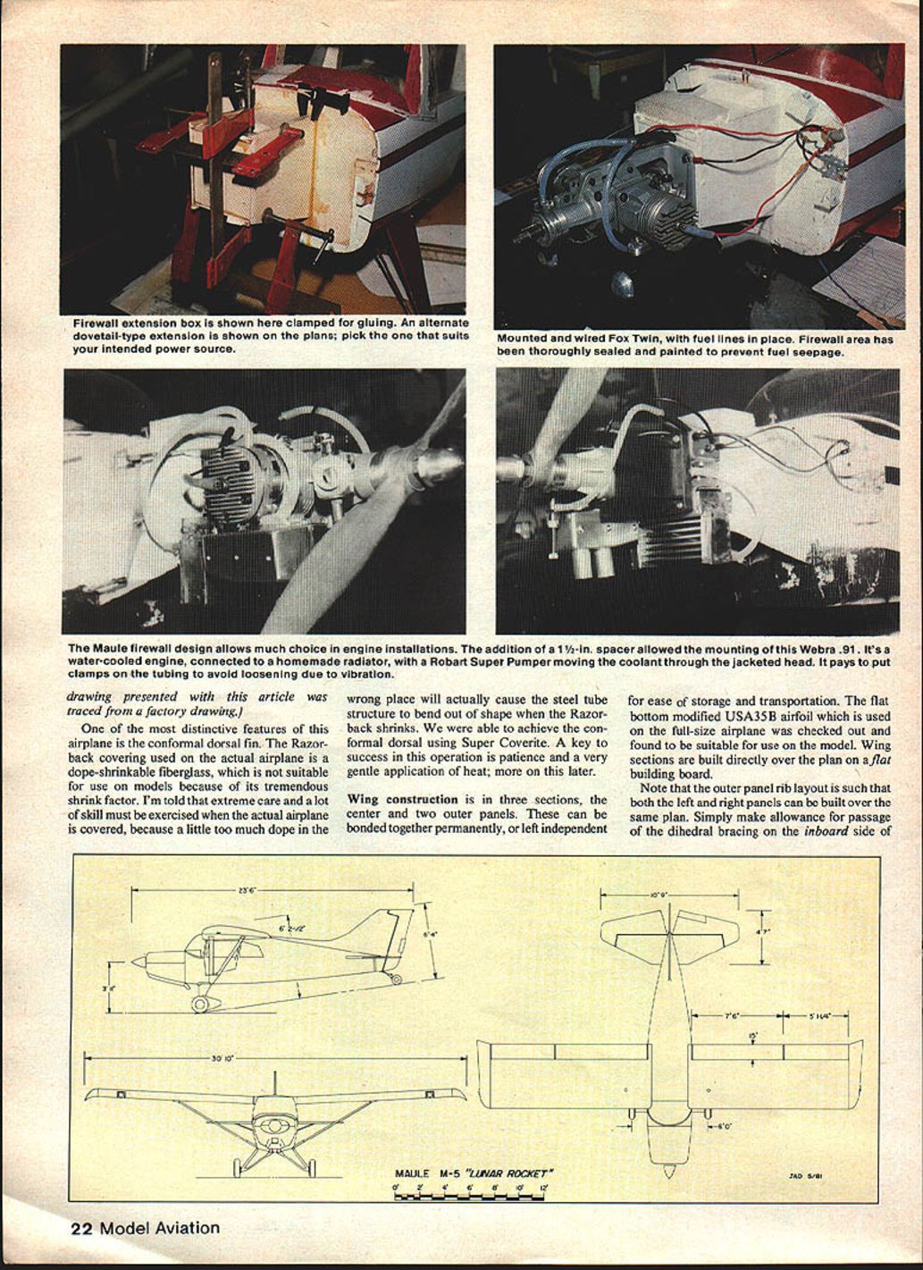
- The firewall extension box shown on the plans is glued in as a dovetail-type extension; pick the style that suits your intended power source. Be sure the firewall area has been thoroughly sealed and painted to prevent fuel seepage.
- Maule firewall design allows a wide choice of engine installations. In our model a 1‑1/2" spacer was used to mount a Webra water‑cooled engine; the Webra was connected to a homemade radiator and a Robart Super Pumper was used to move coolant through the jacketed head. Be sure to put clamps on the tubing to prevent loosening due to vibration.
- The engine box assembly can now be fabricated and epoxied to the firewall. Note that the length of this box will depend upon the particular engine and mount you will use, so double-check the spinner backplate-to-firewall dimension prior to cutting the box parts.
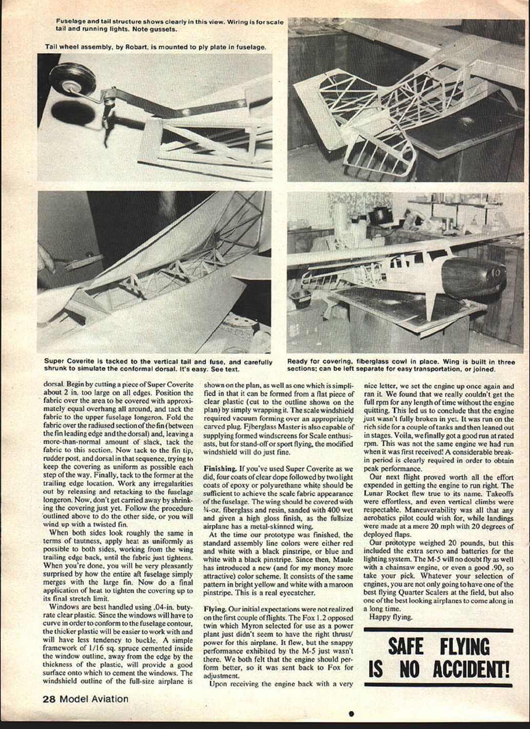
- A fiberglass cowl was used on our prototype; you can purchase a duplicate from Fiberglass Master, P.O. Box 134M, Bayshore, NY 11706, or make one yourself from the cross sections given on the plan.
Conformal dorsal and covering
- Shape and cement the 1/4" balsa dorsal continuation over the wing center section starting at the trailing edge.
- Balsa filler blocks should be cemented to the center section over the hold‑down bolt locations and then shaped to conform to the slope which the fabric covering will assume.
Conformal-dorsal covering with Super Coverite:
- Cut a piece of Super Coverite about 2 in. too large on all edges.
- Position the fabric over the area to be covered with approximately equal overhang all around and tack the fabric to the upper fuselage longeron.
- Fold the fabric over the radiused section of the fin (between the fin leading edge and the dorsal), leaving a bit more slack than usual, and tack the fabric to this section.
- Tack to the fin tip, rudder post, and dorsal in that sequence, trying to keep the covering as uniform as possible each step of the way. Finally, tack to the former at the trailing-edge location.
- Work any irregularities out by releasing and retacking to the fuselage longeron. Do not shrink yet.
- Repeat the procedure on the other side to avoid a twisted fin.
- When both sides look roughly the same in tautness, apply heat uniformly to both sides, working from the wing trailing edge back, until the fabric just tightens.
- Do a final application of heat to tighten the covering up to its final stretch limit.
Windows and windscreen
- Windows: use 0.04‑in. butyrate clear plastic. The thicker plastic will be easier to curve and will have less tendency to buckle.
- Install a simple framework of 1/16" sq. spruce cemented inside the window opening, away from the edge by the thickness of the plastic; this provides a good surface to cement the windows.
- Windshield: the full-size windshield outline is shown on the plan and a simplified version is provided that can be formed from a flat piece of clear plastic by wrapping it. The scale windshield requires vacuum forming over an appropriately carved plug.
- Fiberglass Master can supply formed windscreens for scale enthusiasts; for stand‑off or sport flying, the modified/wrap windshield will suffice.
Finishing
- If you've used Super Coverite, four coats of clear dope followed by two light coats of epoxy or polyurethane white should be sufficient to achieve the scale fabric appearance of the fuselage.
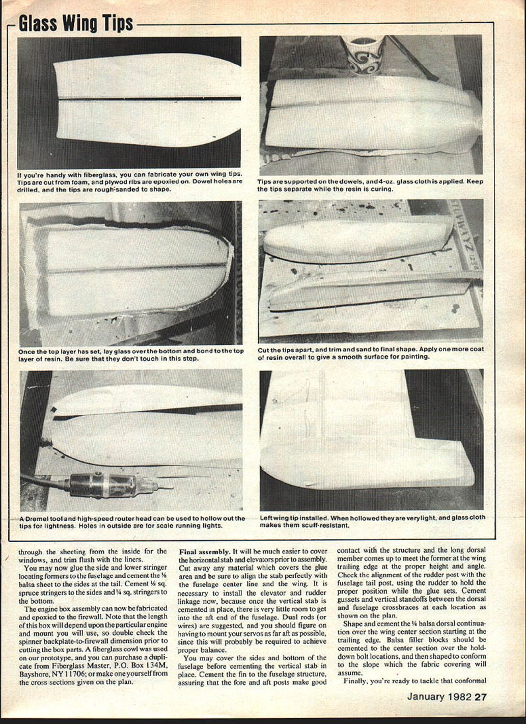
- The wing should be covered with 3/4‑oz. fiberglass and resin, sanded with 400‑grit wet and given a high-gloss finish, as the full-size airplane has a metal-skinned wing.
Color schemes used on the prototype:
- Red and white with a black pinstripe.
- Blue and white with a black pinstripe.
- Newer scheme: bright yellow and white with a maroon pinstripe (a real eye-catcher).
Final assembly
- It is much easier to cover the horizontal stab and elevators prior to assembly. Cut away any material that covers the glue area and be sure to align the stab perfectly with the fuselage centerline and the wing.
- Install the elevator and rudder linkage now, because once the vertical stab is cemented in place there is very little room to get into the aft end of the fuselage. Dual rods (or wires) are suggested.
- Mount servos as far aft as possible, since this will probably be required to achieve proper balance.
- You may cover the sides and bottom of the fuselage before cementing the vertical stab in place.
- Cement the fin to the fuselage structure, assuring that the fore and aft posts make good contact with the structure and the long dorsal member comes up to meet the former at the wing trailing edge at the proper height and angle.
- Check the alignment of the rudder post with the fuselage tail post, using the rudder to hold the proper position while the glue sets.
- Cement gussets and vertical standoffs between the dorsal and fuselage crossbraces at each location as shown on the plan.
Flying
Our initial expectations were not realized on the first couple of flights. The Fox 1.2 opposed twin which Myron selected as a power plant just didn't seem to have the right thrust-to-weight ratio for this airplane. It flew, but the snappy performance exhibited by the M-5 wasn't there. The engine was sent back to Fox for adjustment.
Upon receiving the engine back we found we couldn't get full rpm for any length of time without the engine quitting. This indicated the engine wasn't fully broken in. It was run on the rich side for a couple of tanks and then leaned out in stages. After break-in we finally got a good run at rated rpm — not the same engine performance as initially received. A considerable break-in period is required to obtain peak performance.
After proper break-in the Lunar Rocket flew true to its name. Takeoffs were effortless and vertical climbs respectable. Maneuverability was excellent for aerobatics, while landings were made at a mere 20 mph with 20° of flap deployed.
Our prototype weighed 20 lb, including the extra servo and batteries required for the lighting system. The M-5 will fly well with a chainsaw engine or even a good .90—take your pick. Whatever engine you choose, you'll have one of the best flying Quarter Scalers at the field and one of the best-looking airplanes to come along in a long time.
Happy flying.
Transcribed from original scans by AI. Minor OCR errors may remain.

