
Max-a-million: 450
Harry Murphy
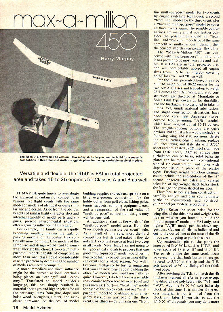
Versatile and flexible, the "450" is FAI in total projected area and takes .15 to .25 engines for Classes A and B as well.
IT MAY BE quite timely to re-evaluate the apparent advantages of competing various free flight events with the same model or models of identical or quite similar size and design. Aside from the obvious benefits of similar flight characteristics and interchangeability of model parts and engines, present environmental situations offer a growing influence in this regard.
For example, the family car is rapidly becoming smaller, making the task of packing models for the contest trek continually more complex. Like models of the same size and design would tend to somewhat alleviate this chore. However, "multi-purpose" models capable of competing in more than one class could considerably ease the problem by decreasing the number of models required to compete.
A more immediate and direct influence might be the current national emphasis being placed on "ecology" and "economy." Translated to model builder's language, this has simply resulted in material shortages and higher prices for all the necessary items from glue, dope, and balsa wood to engines, timers, and associated hardware. As the cost of model building supplies skyrockets, sprinkle on a little ever-present competition for the hobby dollar from golf clubs, fishing poles, tennis racquets, camping equipment, etc., and a reappraisal of the real value of "multi-purpose" competition designs may well be beneficial.
An additional slant at the worth of the "multi-purpose" model arises from the "two models permissible per event" rule. As a result of this rule, most die-hard competitors feel stripped naked if they do not start a contest season at least two deep in all events. Never fear. I am not going to be hypocritical enough to propose that one good "multi-purpose" model would permit you to be highly competitive in three different events for a whole season. Nor will I tax your intelligence by further suggesting that you can now forget about building the other five models you would normally require. However, I do feel there is a sensible compromise somewhere between (one) and (six) such as: (four) — a "front line" model for each of the three events and one "multi-purpose" model to be utilized as an emergency backup in any one of the three events; or (three) — by utilizing one "front line multi-purpose" model for two events by engine switching techniques, a second "front line" model for the third event, plus a "backup multi-purpose" model to cover all three events again. The sensible combinations are many and if you further consider the possibilities should all "front line" and "backup" models be of the same competitive multi-purpose design, then the concept affords even greater flexibility.
The "Max-A-Million 450" was conceived with "multi-purpose" in mind, and it has proven to be most versatile and flexible. It is FAI size in total projected area and will comfortably accept all engine sizes from .15 to .25 thereby covering both Class "A" and "B" as well.
Per the plans presented here, it can be built to weigh out at 20-22 ounces for the two AMA Classes and leaded-up to weigh 26.5 ounces for FAI. Wing and stab constructions are directed at Monokote or Solar Film type coverings for durability and the fuselage is also designed to take its lumps. Yet, simple material substitutions and slight construction deviations have produced very light Japanese tissue-covered trophy-winning "A/B" models which have weighed out at 16-18 ounces.
The weight-reducing options are quite obvious, but to list a few would include the following wing and stab revisions: delete the wing leading edge planking; replace 1/8" sheet wing and stab ribs with 3/32" sheet and designate 3/32" sheet ribs made 1/16" sheet; 3/32" sq. spruce wing turbulators can be balsa; solid balsa tip plates can be replaced with conventional slanted rib construction; and cover with Japanese tissue in place of the plastic types. Fuselage weight reduction changes could include the substitution of the 1/8" spruce longerons by balsa and careful selection of lightweight sheet balsa stock for fuselage and plybon-sheeted surfaces.
Therefore, before starting construction, carefully analyze and plan your ultimate particular requirements and construct your model (or models) accordingly.
Wing: Select the sheet balsa for the wing ribs of the thickness and weight relative to the motor you intend to build — the "multi-purpose" model, an FAI only, or a lighter "A/B" model per the above suggestions. Cut out all ribs as indicated and cut to the detail line at the nose of the ribs. Pin the inner panel 3/8" x 1/2" L.E., 1/4" x T.E., and lower spars of 3/16" x 1/8" and 1/8" x 1/4". The plans utilize the same stock sizes; however, note that both bottom spars get tapered to 3/16" at the tip and the T.E. gets tapered to 3/16" by slicing off the thick front edge.
After notching the T.E. to match the rib thickness, cement all ribs in place except the dihedral and plywood ribs "W1" and "W3". Add the 1/16" x 1/8" soft balsa tip block at this time. It is simpler if the excess material is not trimmed from the block until later. If you wish to add the 1/16" x 1/16" diagonals, you may do so more easily before sheeting. easily at this time, except omit those either side of the polyhedral breaks for now. The diagonals lie on top of the lower spar and are also cemented to it. Originally, I added these on a model slated especially for "FAI" use as a method of adding a little more strength and I needed extra weight added somewhere anyway, but structurally they would probably be more beneficial on a very light wing. Do not add the top spars and turbulators as yet, for it is a lesser task if they are added after the polyhedral and dihedral are set.
Remove only the wing tip panels from the plans and re-cement all joints. Carve the bottom of the tip blocks across the end section diagonal as indicated, but do not finish trim the top until after the top spars and turbulators have been added.
Trim and cement the tip panels to the inner panels which are still pinned to the plans, blocking them up to the 3/8" polyhedral angle. Add the 1/16" plywood polyhedral braces "WD" and "WE" as shown and follow with the "W3" rib. The 1/8" x 3/16" top spar and 3/32" sq. turbulators may now be cemented in place on the tip panels only. When cement has set, remove the two wing halves from the plans and re-cement the remaining joints.
I prefer to finish trim and sand the wing tips at this stage as it is easier to manipulate one-half a wing rather than the entire wing. Trim and align the two wing halves by blocking them up to the 1 3/4° dihedral angle and cement securely. Cement in place the 1/16" plywood dihedral braces "WA" and "WB", then the 1/32" plywood braces "WC", and follow with the center rib "W1." While this is thoroughly drying, you can start adding the remaining 3/16" x 3/16" top spars and 3/32" sq. turbulators to the inner panels.
After removing the one-piece wing from the plans, add the appropriate rib gussets, the remaining diagonals adjoining the polyhedral breaks, the 1/16" sheet balsa leading edge planking, plus the center section planking as indicated. Carve away all excess balsa and finish sand with 400 grit sandpaper. Sand to a very smooth surface if you are intending to use the miracle plastic film coverings. I prefer to use transparent Monokote as it appears lighter and less brittle than opaque colors. Solar Film, I find to provide less surface tension than Monokote, but it will suffice.
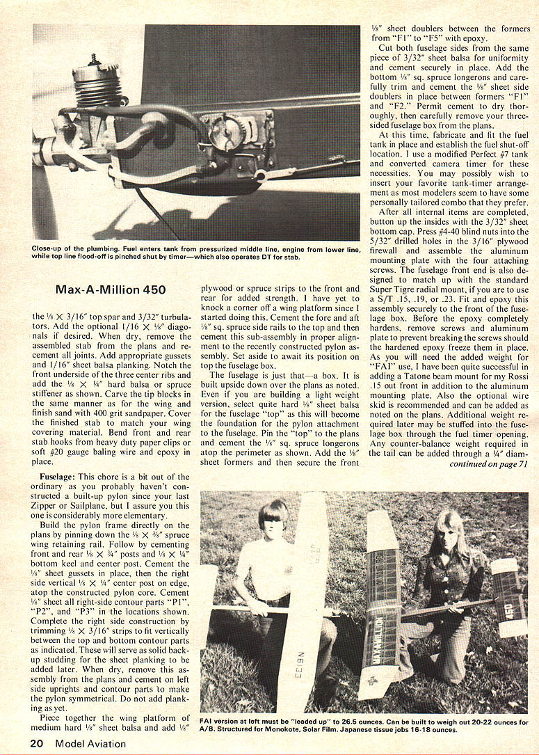
Stabilizer: Obviously, the same basic construction procedure is followed here as per the wing. It may even seem as though you are building a fifth wing panel as you proceed. Cut all 1/8" stab ribs from your selected balsa sheet stock. Pin the 1/4" x 3/8" L.E., 3/16" x 1/4" T.E. and dual 1/8" x 3/16" bottom spars in place on the plans. Notch the T.E. and cement all the ribs in place. Add the 3/8" x 1/2" blocks and follow with
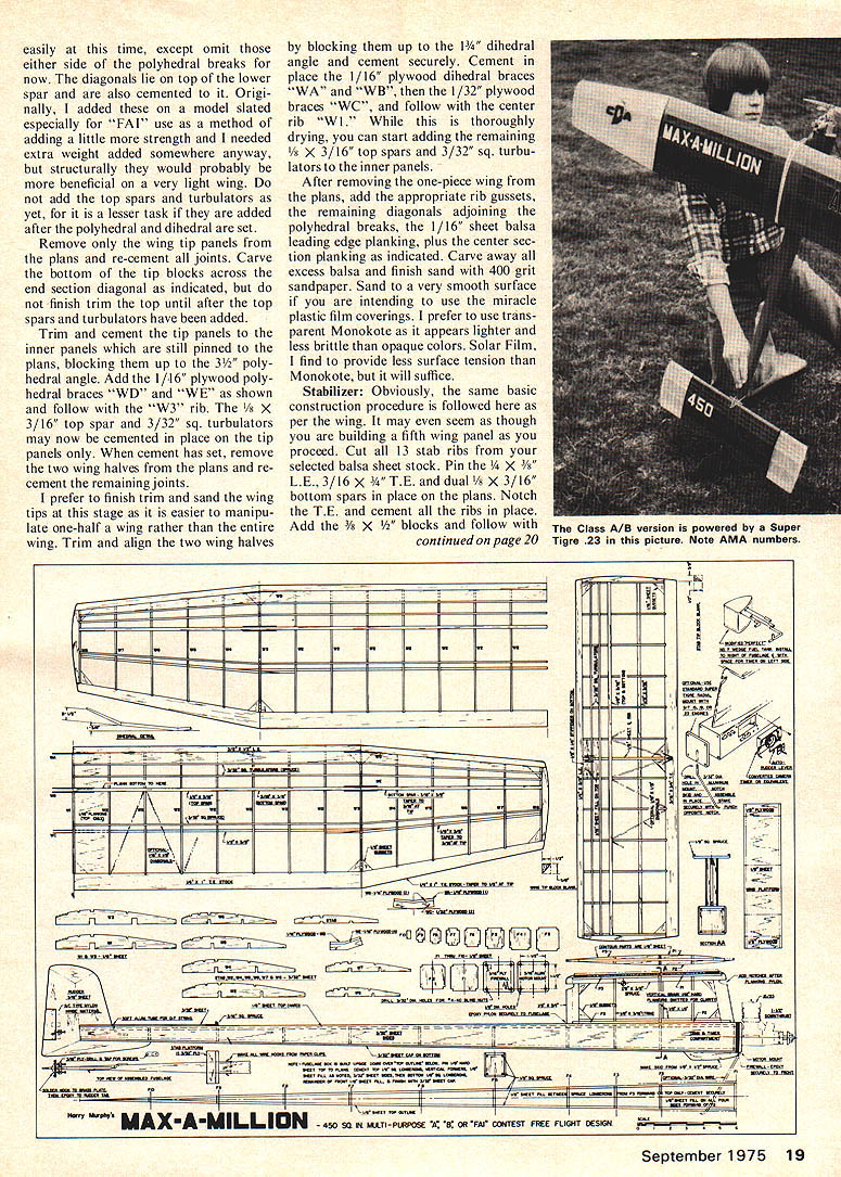
Max-A-Million 450
the 1/8" x 3/16" top spar and 3/32" turbulators. Add the optional 1/16" x 5/8" diagonals if desired. When dry, remove the assembled stab from the plans and re-cement all joints. Add appropriate gussets and 1/16" sheet balsa planking. Notch the front underside of the three center ribs and add the 1/8" x 1/4" hard balsa or spruce stiffener as shown. Carve the tip blocks in the same manner as for the wing and finish sand with 400 grit sandpaper. Cover the finished stab to match your wing covering material. Bend front and rear stab hooks from heavy duty paper clips or soft #20 gauge baling wire and epoxy in place.
Fuselage: This chore is a bit out of the ordinary as you probably haven't constructed a built-up pylon since your last Zipper or Sailplane, but I assure you this one is considerably more elementary.
Build the pylon frame directly on the plans by pinning down the 1/8" x 5/8" spruce wing retaining rail. Follow by cementing front and rear 1/8" x 3/4" posts and 1/8" x 1/4" bottom keel and center post. Cement the 1/8" sheet gussets in place, then the right side vertical 1/8" x 1/4" center post on edge, atop the constructed pylon core. Cement 1/8" sheet all right-side contour parts "P1", "P2", and "P3" in the locations shown. Complete the right side construction by trimming 1/8" x 3/16" strips to fit vertically between the top and bottom contour parts as indicated. These will serve as solid backing studding for the sheet planking to be added later. When dry, remove this assembly from the plans and cement on left side uprights and contour parts to make the pylon symmetrical. Do not add planking as yet.
Piece together the wing platform of medium hard 1/8" sheet balsa and add 1/8" plywood or spruce strips to the front and rear for added strength. I have yet to knock a corner off a wing platform since I started doing this. Cement the fore and aft 5/32" spruce side rails to the top and then cement this sub-assembly in proper alignment to the recently constructed pylon assembly. Set aside to await its position on top of the fuselage box.
The fuselage is just that — a box. It is built upside down over the plans as noted. Even if you are building a light weight version, select quite hard 1/8" sheet balsa for the fuselage "top" as this will become the foundation for the pylon attachment to the fuselage. Pin the "top" to the plans and cement the 1/8" sq. spruce longerons atop the perimeter as shown. Add the 1/8" sheet formers and then secure the front 1/8" sheet doublers between the formers from "F1" to "F5" with epoxy.
Cut both fuselage sides from the same piece of 3/32" sheet balsa for uniformity and cement securely in place. Add the bottom 5/32" sq. spruce longerons and carefully trim and cement the 1/8" sheet side doublers in place between formers "F1" and "F2". Permit cement to dry thoroughly, then carefully remove your three-sided fuselage box from the plans.
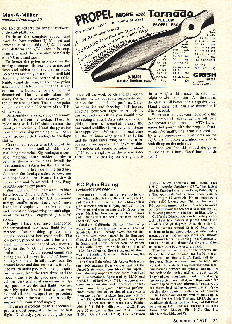
At this time, fabricate and fit the fuel tank in place and establish the fuel shut-off location. I use a modified Perfect "A" tank and converted camera timer for these necessities. You may possibly wish to insert your favorite tank-timer arrangement as most modelers seem to have some personally tailored combo that they prefer.
After all internal items are completed, button up the insides with the 3/32" sheet bottom cap. Press #4-40 blind nuts into the 5/32" drilled holes in the 3/16" plywood firewall and assemble the aluminum mounting plate with the four attaching screws. The fuselage front end is also designed to match up with the standard Super Tigre radial mount, if you are to use a S/T .15, .19, or .23. Fit and epoxy this assembly securely to the front of the fuselage box. Before the epoxy completely hardens, remove screws and aluminum plate to prevent breaking the screws should the hardened epoxy freeze them in place. As you will need the added weight for "FAI" use, I have been quite successful in adding a Tatone beam mount for my Rossi .15 out front in addition to the aluminum mounting plate. Also, the optional wire skid is recommended and can be added as noted on the plans. Additional weight required later may be stuffed into the fuse-
Max-a-million: 450
lage. A center hole drilled into the top just rearward of the stab platform.
Fabricate the complete rudder and lower fin from medium 3/16" sheet and cement in place. Add the 3/32" plywood stab platform and 3/32" sheet balsa cap. Trim and sand this assembly completely with 400 grit sandpaper.
To locate the pylon assembly on the fuselage, temporarily assemble engine and timer and rubber-band the stab in place. Teeter this assembly on a round pencil laid diagonally across the corner of a table. Rubber-band the wing to the loose pylon assembly and slide them along the fuselage top until the horizontal balance point is determined. Then carefully align and epoxy the pylon assembly securely to the top of the fuselage box. The balance point should locate about 3" forward of the T.E. of the wing.
Disassemble the wing, stab and remove all hardware from the fuselage. Plank the pylon area with 1/16" sheet running the wood grain vertically. Notch the pylon for front and rear wing retaining hooks. Sand the entire completed fuselage to pre-dope status.
Cut the auto-rudder trim tab out of the rudder area and re-install with thin nylon R/C hinge material. Auto rudder hardware detail is shown on the plans. Install the bent aluminum tubing for the D-T string to come out the left side of the fuselage. Complete the fuselage either by covering with doped-on colored tissue or finish with epoxy resin and follow with Hobby-Poxy or K & B Super Poxy paints.
Start adding final hardware, rubber band hooks, D-T, and A/R string guides of short lengths of 1/16" I.D. aluminum tubing, snuffer tube, timer, A/R timer lever, etc. Completely assemble the model and cement on proper wing and stab alignment keys using 1/4" lengths of 1/16 × 1/8" spruce.
Flying: I have long since abandoned the conventional new model flight testing methods after smashing up too many models because of low speed stalls. The low power, prop on backwards, horizontal hand launch was exchanged very successfully for the VTO, full power, "go for broke" method. A 2-3 second engine run giving you full power from VTO launch, hauls your model directly away from the ground faster and does not permit time for it to return under power. Your engine quits further away from the terra firma and the model arrives into the glide more realistically as it is traveling at a more normal flying speed. After the first flight, you are probably quite close to final trim as you skipped all that low-speed test procedure which is not in the normal competition flying mode for your model anyway.
The main ingredient for this approach is proper model preparation before the first flight. Obviously, you cannot vary wing model off the work bench and zap out to the test site without some reasonable idea of how the model should perform. Careful eyeballing and checking of all factors affecting power-on flight characteristics are required (something you should have been doing anyway). As a right power-right glide pattern is suggested, insure the horizontal stabilizer is perfectly flat, steam in an approximate 1/8" washout in each wing tip; the left inner wing panel is to be flat and the right inner wing panel is to incorporate an approximate 3/32" wash-in. The rudder tab should be adjusted about 1/16" to the right with the engine side-thrust zero to possibly some slight left-thrust. A 1/16" shim under the stab T.E. might be wise at the start. A little stall in the glide is still better than a negative dive. Hand gliding tests can also determine if this is needed.
When satisfied that your homework has been completed, set the fuel shut-off for a 2-3 second engine run and VTO launch under full power with the prop on frontwards. Normally, final trim is completed by a few screwdriver adjustments on the A/R tab for power and glide and a little stab tilt up for the right side.
I hope you find this model design as rewarding as I have. Good luck and sic 'em!!
Transcribed from original scans by AI. Minor OCR errors may remain.

